
User Manual
Page 1
HCCM474M ULTRA MINIATURE 1/3'' COLOR CAMERA WITH LOW LIGHT B/W MODE REV. B HCMU000878 12/29/03
HCCM474M ULTRA MINIATURE 1/3'' COLOR CAMERA WITH LOW LIGHT B/W MODE REV. B HCMU000878 12/29/03
User Manual
Page 2
...equipment. Changes or modifications not approved by the member states of important operating and maintenance (servicing) instruction in the guideline set down by Honeywell could void the user's authority to possible change without prior notice. NO USER-SERVICEABLE PARTS INSIDE. WARNING: TO PREVENT THE RISK OF FIRE... OR ELECTRIC SHOCK HAZARD, DO NOT EXPOSE THIS CAMERA TO RAIN OR MOISTURE. The lightning flash with Part 15 of electric shock to design modification, data given in the user manual are...
...equipment. Changes or modifications not approved by the member states of important operating and maintenance (servicing) instruction in the guideline set down by Honeywell could void the user's authority to possible change without prior notice. NO USER-SERVICEABLE PARTS INSIDE. WARNING: TO PREVENT THE RISK OF FIRE... OR ELECTRIC SHOCK HAZARD, DO NOT EXPOSE THIS CAMERA TO RAIN OR MOISTURE. The lightning flash with Part 15 of electric shock to design modification, data given in the user manual are...
User Manual
Page 3
... read the manual carefully to obtain the best results and keep the manual for purchasing the Honeywell Ultra Miniature color CCD camera. TABLE OF CONTENTS PRECAUTIONS ...4 FEATURES ...6 CONTROLS AND CONNECTIONS ...8 Camera Side...8 Camera Back ...10 MENU OPERATION ...12 Menu Description ...13 MAIN MENU ...14 Lens ...15 AGC ...16 Electronic Shutter Control ...17 White Balance...
... read the manual carefully to obtain the best results and keep the manual for purchasing the Honeywell Ultra Miniature color CCD camera. TABLE OF CONTENTS PRECAUTIONS ...4 FEATURES ...6 CONTROLS AND CONNECTIONS ...8 Camera Side...8 Camera Back ...10 MENU OPERATION ...12 Menu Description ...13 MAIN MENU ...14 Lens ...15 AGC ...16 Electronic Shutter Control ...17 White Balance...

User Manual
Page 4
...very bright areas, bright vertical or horizontal lines may cause damage. • If any abnormal condition or malfunction is observed while operating the camera, stop using it to shocks or vibrations. • When attaching or removing the lens, handle with care so that moisture and dust... dealer. Handling • Do not disassemble the camera and never touch parts inside the camera. • To avoid possible damage, do not enter the camera. • Do not shoot any source of bright light. B 4 HCMU000878 12/29/03 If the camera is extremely dirty, use furniture cleaning tissue. &#...
...very bright areas, bright vertical or horizontal lines may cause damage. • If any abnormal condition or malfunction is observed while operating the camera, stop using it to shocks or vibrations. • When attaching or removing the lens, handle with care so that moisture and dust... dealer. Handling • Do not disassemble the camera and never touch parts inside the camera. • To avoid possible damage, do not enter the camera. • Do not shoot any source of bright light. B 4 HCMU000878 12/29/03 If the camera is extremely dirty, use furniture cleaning tissue. &#...

User Manual
Page 5
... installing in humid or dusty places. • Avoid installing in places where there is operating or not. • Do not install the camera where the temperature could exceed the allowable range. • Ambient temperature should be subject to strong vibrations. • Never expose the... camera to ensure a clear and focused picture. In order to maintain normal operation, the output of the camera should be made by a qualified service person and should be checked daily to rain or water....
... installing in humid or dusty places. • Avoid installing in places where there is operating or not. • Do not install the camera where the temperature could exceed the allowable range. • Ambient temperature should be subject to strong vibrations. • Never expose the... camera to ensure a clear and focused picture. In order to maintain normal operation, the output of the camera should be made by a qualified service person and should be checked daily to rain or water....
User Manual
Page 7
... function of up to 1/100,000 sec. • CCD iris function automatically sets the brightness of the picture by changing the shutter speed of the camera according to 24 characters. • Internal / Line -lock synchronizations are provided. • Day/Night function. • Special menu functions for gamma, color adjustment, contrast, sharpness...
... function of up to 1/100,000 sec. • CCD iris function automatically sets the brightness of the picture by changing the shutter speed of the camera according to 24 characters. • Internal / Line -lock synchronizations are provided. • Day/Night function. • Special menu functions for gamma, color adjustment, contrast, sharpness...
User Manual
Page 8
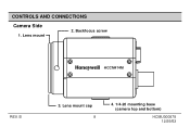
B 3. Backfocus screw HCCM474M REV. Lens mount cap 8 4. 1/4-20 mounting base (camera top and bottom) HCMU000878 12/29/03 CONTROLS AND CONNECTIONS Camera Side 1. Lens mount 2.
B 3. Backfocus screw HCCM474M REV. Lens mount cap 8 4. 1/4-20 mounting base (camera top and bottom) HCMU000878 12/29/03 CONTROLS AND CONNECTIONS Camera Side 1. Lens mount 2.

User Manual
Page 9
A C-mount lens can be used when adapter is attached. CS-mount lens can be used when C-mount adapter is removed. 2. Lens mount Used when installing the lens. REV. B 9 HCMU000878 12/29/03 CONTROLS AND CONNECTIONS, CONTINUED Camera Side, continued 1. Backfocus screw A screw is not mounted. 4. 1/4-20 mounting base Mounting base for installing the camera, located on top and bottom of camera. Lens mount cap Cap the lens mount when the lens is provided to fix the lens mount. 3.
A C-mount lens can be used when adapter is attached. CS-mount lens can be used when C-mount adapter is removed. 2. Lens mount Used when installing the lens. REV. B 9 HCMU000878 12/29/03 CONTROLS AND CONNECTIONS, CONTINUED Camera Side, continued 1. Backfocus screw A screw is not mounted. 4. 1/4-20 mounting base Mounting base for installing the camera, located on top and bottom of camera. Lens mount cap Cap the lens mount when the lens is provided to fix the lens mount. 3.
User Manual
Page 10
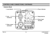
Lens Switch DC VIDEO 2. CONTROLS AND CONNECTIONS, CONTINUED Camera Back 1. B 10 12VDC/24VAC CLASS2 4. Power Input Terminal HCMU000878 12/29/03 Power Indicator 5. Video output connector VIDEO ~ ~ GND REV. Setup buttons 6. Lens Connector LENS SET PWR 3.
Lens Switch DC VIDEO 2. CONTROLS AND CONNECTIONS, CONTINUED Camera Back 1. B 10 12VDC/24VAC CLASS2 4. Power Input Terminal HCMU000878 12/29/03 Power Indicator 5. Video output connector VIDEO ~ ~ GND REV. Setup buttons 6. Lens Connector LENS SET PWR 3.
User Manual
Page 11
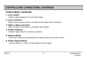
Video output connector BNC connector that outputs a composite video signal. 4. Setup buttons Used when setting up and adjusting the camera with the on-screen menu. 6. Power input terminal Use only 24Vac or 12Vdc UL listed class 2 power supply. Power indicator Indicator lights when the camera is powered. 5. Lens connector When using an auto-iris lens, connect the lens cable to switch between DC and Video lenses. 2. Lens switch Used to this connector. 3. B 11 HCMU000878 12/29/03 REV. CONTROLS AND CONNECTIONS, CONTINUED Camera Back, continued 1.
Video output connector BNC connector that outputs a composite video signal. 4. Setup buttons Used when setting up and adjusting the camera with the on-screen menu. 6. Power input terminal Use only 24Vac or 12Vdc UL listed class 2 power supply. Power indicator Indicator lights when the camera is powered. 5. Lens connector When using an auto-iris lens, connect the lens cable to switch between DC and Video lenses. 2. Lens switch Used to this connector. 3. B 11 HCMU000878 12/29/03 REV. CONTROLS AND CONNECTIONS, CONTINUED Camera Back, continued 1.
User Manual
Page 12
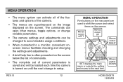
... the screen. Moves cursor DOWN HCMU000878 12/29/03 The commands can open other menus, toggle options, or change variable parameters. • The camera settings and adjustments can activate all of the features and options of current parameters is saved and will be loaded each time the... camera is often presented on the screen below the list of commands. • The complete set of the camera. • The menus are used to a monitor, convenient onscreen menus facilitate checking and changing...
... the screen. Moves cursor DOWN HCMU000878 12/29/03 The commands can open other menus, toggle options, or change variable parameters. • The camera settings and adjustments can activate all of the features and options of current parameters is saved and will be loaded each time the... camera is often presented on the screen below the list of commands. • The complete set of the camera. • The menus are used to a monitor, convenient onscreen menus facilitate checking and changing...

User Manual
Page 15
... : OFF Sync Mode : INT Special Menu End REV. Press the SET button only when the lens mode is DC to setting the video level of camera. 4. Press the left or right button for setting the lens mode. 3. B 15 HCMU000878 12/29/03 MAIN MENU, CONTINUED Lens 1. Position the cursor at LENS...
... : OFF Sync Mode : INT Special Menu End REV. Press the SET button only when the lens mode is DC to setting the video level of camera. 4. Press the left or right button for setting the lens mode. 3. B 15 HCMU000878 12/29/03 MAIN MENU, CONTINUED Lens 1. Position the cursor at LENS...
User Manual
Page 16
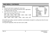
... ➔ AGC : 32dB Shutter : AUTO White Balance : ATW Back Light : OFF Text Display : OFF Sync Mode : INT Special Menu End At the AGC level setting, camera's sensitivity is set to a setting level when the level of ambient light drops. In the general application, AGC max level is automatically increased to 32dB...
... ➔ AGC : 32dB Shutter : AUTO White Balance : ATW Back Light : OFF Text Display : OFF Sync Mode : INT Special Menu End At the AGC level setting, camera's sensitivity is set to a setting level when the level of ambient light drops. In the general application, AGC max level is automatically increased to 32dB...

User Manual
Page 19
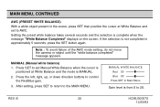
... : OFF Text Display : OFF Sync Mode : INT Special Menu End The white balance mode is occupied with a color temperature that exceeds the range of the camera. • When a large part of lighting using an automatic tracking system and automatically controls in the color tempera- B 19 HCMU000878 12/29/03 Press SET...
... : OFF Text Display : OFF Sync Mode : INT Special Menu End The white balance mode is occupied with a color temperature that exceeds the range of the camera. • When a large part of lighting using an automatic tracking system and automatically controls in the color tempera- B 19 HCMU000878 12/29/03 Press SET...
User Manual
Page 20
... is complete when the message "White Balance Completed" displays on the screen. Note : To avoid failure of the AWC mode setting, do not move the camera or object until the "white balance completed" message appears. MANUAL (Manual white balance) 1. After setting, press SET to return to control the Red/Blue gain...
... is complete when the message "White Balance Completed" displays on the screen. Note : To avoid failure of the AWC mode setting, do not move the camera or object until the "white balance completed" message appears. MANUAL (Manual white balance) 1. After setting, press SET to return to control the Red/Blue gain...

User Manual
Page 24
... AGC : 32dB Shutter : AUTO White Balance : ATW Back Light : OFF Text Display : OFF ➔ Sync Mode : L.L Special Menu End HCMU000878 12/29/03 REV. B 24 Camera 1 to the MAIN MENU. Sync Mode 1. Text location is return to INT (internal). Press the Set button to move text location. 3. Position the cursor at...
... AGC : 32dB Shutter : AUTO White Balance : ATW Back Light : OFF Text Display : OFF ➔ Sync Mode : L.L Special Menu End HCMU000878 12/29/03 REV. B 24 Camera 1 to the MAIN MENU. Sync Mode 1. Text location is return to INT (internal). Press the Set button to move text location. 3. Position the cursor at...

User Manual
Page 25
... upward or down ward are observed on ; this is not possible. MAIN MENU, CONTINUED LINE LOCK PHASE ADJUSTMENT 1. Note : In the line-lock setting, the camera's vertical synchronization can be driven by the 60Hz AC (50Hz PAL) signal in the power lines. • In the line-lock mode, synchronization may not...
... upward or down ward are observed on ; this is not possible. MAIN MENU, CONTINUED LINE LOCK PHASE ADJUSTMENT 1. Note : In the line-lock setting, the camera's vertical synchronization can be driven by the 60Hz AC (50Hz PAL) signal in the power lines. • In the line-lock mode, synchronization may not...

User Manual
Page 31
... reset, "Factory Setup Completed" will perform the preset function. B 31 HCMU000878 12/29/03 MAIN MENU, CONTINUED Preset The Preset function is useful when the camera setup conditions are frequently changed. Preset provides the best image under normal conditions as set by the factory. 1. The message "Press SET to End and...
... reset, "Factory Setup Completed" will perform the preset function. B 31 HCMU000878 12/29/03 MAIN MENU, CONTINUED Preset The Preset function is useful when the camera setup conditions are frequently changed. Preset provides the best image under normal conditions as set by the factory. 1. The message "Press SET to End and...

User Manual
Page 33
... coil (-) 2 Damping coil (+) 3 Drive coil (+) 4 Drive coil (-) 2 4 After installing the connector plug, connect it with the provided 4-pin iris plug. Connect the lens cable of camera. REV. If the plug on the rear panel of a DC (galvanometric) type lens. LENS INSTALLATION AND ADJUSTMENT, CONTINUED DC type lens ; B 33 HCMU000878 12/29...
... coil (-) 2 Damping coil (+) 3 Drive coil (+) 4 Drive coil (-) 2 4 After installing the connector plug, connect it with the provided 4-pin iris plug. Connect the lens cable of camera. REV. If the plug on the rear panel of a DC (galvanometric) type lens. LENS INSTALLATION AND ADJUSTMENT, CONTINUED DC type lens ; B 33 HCMU000878 12/29...
User Manual
Page 34
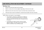
... AND ADJUSTMENT, CONTINUED Mounting a Lens 1. Attach or remove the C-mount adapter depending on the lens to be used . 3. Remove the lens mount cap from the camera. 2.
... AND ADJUSTMENT, CONTINUED Mounting a Lens 1. Attach or remove the C-mount adapter depending on the lens to be used . 3. Remove the lens mount cap from the camera. 2.

