
User Manual
Page 1
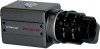
HCCM474M ULTRA MINIATURE 1/3'' COLOR CAMERA WITH LOW LIGHT B/W MODE REV. B HCMU000878 12/29/03
HCCM474M ULTRA MINIATURE 1/3'' COLOR CAMERA WITH LOW LIGHT B/W MODE REV. B HCMU000878 12/29/03
User Manual
Page 2
...the member states of the FCC rules. REV. WARNING: TO PREVENT THE RISK OF FIRE OR ELECTRIC SHOCK HAZARD, DO NOT EXPOSE THIS CAMERA TO RAIN OR MOISTURE. Information for USA: This device complies with arrowhead symbol, within the product's enclosure that all major safety requirements ... risk of important operating and maintenance (servicing) instruction in the user manual are fulfilled as laid out in the guideline set down by Honeywell could void the user's authority to design modification, data given in the literature accompanying the product. CAUTION RISK OF ELECTRIC SHOCK DO NOT ...
...the member states of the FCC rules. REV. WARNING: TO PREVENT THE RISK OF FIRE OR ELECTRIC SHOCK HAZARD, DO NOT EXPOSE THIS CAMERA TO RAIN OR MOISTURE. Information for USA: This device complies with arrowhead symbol, within the product's enclosure that all major safety requirements ... risk of important operating and maintenance (servicing) instruction in the user manual are fulfilled as laid out in the guideline set down by Honeywell could void the user's authority to design modification, data given in the literature accompanying the product. CAUTION RISK OF ELECTRIC SHOCK DO NOT ...
User Manual
Page 3
... Display ...23 Special Menu ...26 LENS INSTALLATION AND ADJUSTMENT ...32 Mounting a Lens...34 Backfocus Adjustment ...35 SPECIFICATIONS ...37 SUPPLIED ACCESSORIES ...40 HONEYWELL VIDEO SYSTEMS ...41 REV. Thank you for future reference. Before using this camera please read the manual carefully to obtain the best results and keep the manual for purchasing the...
... Display ...23 Special Menu ...26 LENS INSTALLATION AND ADJUSTMENT ...32 Mounting a Lens...34 Backfocus Adjustment ...35 SPECIFICATIONS ...37 SUPPLIED ACCESSORIES ...40 HONEYWELL VIDEO SYSTEMS ...41 REV. Thank you for future reference. Before using this camera please read the manual carefully to obtain the best results and keep the manual for purchasing the...

User Manual
Page 4
... subject it to shocks or vibrations. • When attaching or removing the lens, handle with care so that moisture and dust do not enter the camera. • Do not shoot any abnormal condition or malfunction is not a malfunction. Cleaning • Turn the power off and wipe off the dirt... with solid-state pickups and is observed while operating the camera, stop using , check power supply and video output connection. • Power supplied without voltage stabilization or the voltage maintained at 24V±10%AC...
... subject it to shocks or vibrations. • When attaching or removing the lens, handle with care so that moisture and dust do not enter the camera. • Do not shoot any abnormal condition or malfunction is not a malfunction. Cleaning • Turn the power off and wipe off the dirt... with solid-state pickups and is observed while operating the camera, stop using , check power supply and video output connection. • Power supplied without voltage stabilization or the voltage maintained at 24V±10%AC...

User Manual
Page 5
...Avoid installing in places where there is radiation. B 5 HCMU000878 12/29/03 PRECAUTIONS, CONTINUED Installation and storage • Do not point the camera at the sun. Daily Check • Make daily checks for proper operation for long-term continuous operation. • Avoid installing in humid or... dusty places. • Avoid installing in places where the camera would be less than 40°C for surveillance use. This could exceed the allowable range. • Ambient temperature should conform to rain ...
...Avoid installing in places where there is radiation. B 5 HCMU000878 12/29/03 PRECAUTIONS, CONTINUED Installation and storage • Do not point the camera at the sun. Daily Check • Make daily checks for proper operation for long-term continuous operation. • Avoid installing in humid or... dusty places. • Avoid installing in places where the camera would be less than 40°C for surveillance use. This could exceed the allowable range. • Ambient temperature should conform to rain ...
User Manual
Page 7
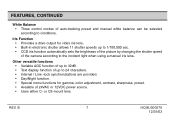
... shutter speeds up to 1/100,000 sec. • CCD iris function automatically sets the brightness of the picture by changing the shutter speed of the camera according to conditions. B 7 HCMU000878 12/29/03 or CS-mount lens. FEATURES, CONTINUED White Balance • Three control modes of 24VAC or 12VDC power source...
... shutter speeds up to 1/100,000 sec. • CCD iris function automatically sets the brightness of the picture by changing the shutter speed of the camera according to conditions. B 7 HCMU000878 12/29/03 or CS-mount lens. FEATURES, CONTINUED White Balance • Three control modes of 24VAC or 12VDC power source...
User Manual
Page 8
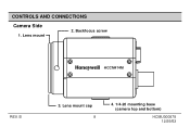
Lens mount cap 8 4. 1/4-20 mounting base (camera top and bottom) HCMU000878 12/29/03 CONTROLS AND CONNECTIONS Camera Side 1. Lens mount 2. B 3. Backfocus screw HCCM474M REV.
Lens mount cap 8 4. 1/4-20 mounting base (camera top and bottom) HCMU000878 12/29/03 CONTROLS AND CONNECTIONS Camera Side 1. Lens mount 2. B 3. Backfocus screw HCCM474M REV.

User Manual
Page 9
A C-mount lens can be used when adapter is attached. CS-mount lens can be used when C-mount adapter is removed. 2. B 9 HCMU000878 12/29/03 CONTROLS AND CONNECTIONS, CONTINUED Camera Side, continued 1. Backfocus screw A screw is not mounted. 4. 1/4-20 mounting base Mounting base for installing the camera, located on top and bottom of camera. REV. Lens mount Used when installing the lens. Lens mount cap Cap the lens mount when the lens is provided to fix the lens mount. 3.
A C-mount lens can be used when adapter is attached. CS-mount lens can be used when C-mount adapter is removed. 2. B 9 HCMU000878 12/29/03 CONTROLS AND CONNECTIONS, CONTINUED Camera Side, continued 1. Backfocus screw A screw is not mounted. 4. 1/4-20 mounting base Mounting base for installing the camera, located on top and bottom of camera. REV. Lens mount Used when installing the lens. Lens mount cap Cap the lens mount when the lens is provided to fix the lens mount. 3.
User Manual
Page 10
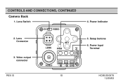
B 10 12VDC/24VAC CLASS2 4. Power Input Terminal HCMU000878 12/29/03 Lens Connector LENS SET PWR 3. Setup buttons 6. CONTROLS AND CONNECTIONS, CONTINUED Camera Back 1. Lens Switch DC VIDEO 2. Power Indicator 5. Video output connector VIDEO ~ ~ GND REV.
B 10 12VDC/24VAC CLASS2 4. Power Input Terminal HCMU000878 12/29/03 Lens Connector LENS SET PWR 3. Setup buttons 6. CONTROLS AND CONNECTIONS, CONTINUED Camera Back 1. Lens Switch DC VIDEO 2. Power Indicator 5. Video output connector VIDEO ~ ~ GND REV.
User Manual
Page 11
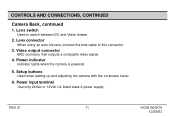
Video output connector BNC connector that outputs a composite video signal. 4. Lens switch Used to this connector. 3. Power input terminal Use only 24Vac or 12Vdc UL listed class 2 power supply. B 11 HCMU000878 12/29/03 REV. Lens connector When using an auto-iris lens, connect the lens cable to switch between DC and Video lenses. 2. Setup buttons Used when setting up and adjusting the camera with the on-screen menu. 6. CONTROLS AND CONNECTIONS, CONTINUED Camera Back, continued 1. Power indicator Indicator lights when the camera is powered. 5.
Video output connector BNC connector that outputs a composite video signal. 4. Lens switch Used to this connector. 3. Power input terminal Use only 24Vac or 12Vdc UL listed class 2 power supply. B 11 HCMU000878 12/29/03 REV. Lens connector When using an auto-iris lens, connect the lens cable to switch between DC and Video lenses. 2. Setup buttons Used when setting up and adjusting the camera with the on-screen menu. 6. CONTROLS AND CONNECTIONS, CONTINUED Camera Back, continued 1. Power indicator Indicator lights when the camera is powered. 5.
User Manual
Page 12
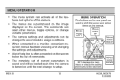
... set of current parameters is saved and will be loaded each time the camera is turned on until the next change variable parameters. • The camera settings and adjustments can activate all of the features and options of the camera. • The menus are used to the next item. The commands can open...
... set of current parameters is saved and will be loaded each time the camera is turned on until the next change variable parameters. • The camera settings and adjustments can activate all of the features and options of the camera. • The menus are used to the next item. The commands can open...

User Manual
Page 15
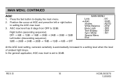
Press the SET button only when the lens mode is DC to setting the video level of camera. 4. MAIN MENU ➔ Lens : DC AGC : 32dB Shutter : AUTO White Balance : ATW Back Light : OFF Text Display : OFF Sync Mode : INT Special Menu End REV. ...
Press the SET button only when the lens mode is DC to setting the video level of camera. 4. MAIN MENU ➔ Lens : DC AGC : 32dB Shutter : AUTO White Balance : ATW Back Light : OFF Text Display : OFF Sync Mode : INT Special Menu End REV. ...
User Manual
Page 16
... ➔ AGC : 32dB Shutter : AUTO White Balance : ATW Back Light : OFF Text Display : OFF Sync Mode : INT Special Menu End At the AGC level setting, camera's sensitivity is set to 32dB. B 16 HCMU000878 12/29/03 MAIN MENU, CONTINUED AGC 1. Press the Set button to a setting level when the level of...
... ➔ AGC : 32dB Shutter : AUTO White Balance : ATW Back Light : OFF Text Display : OFF Sync Mode : INT Special Menu End At the AGC level setting, camera's sensitivity is set to 32dB. B 16 HCMU000878 12/29/03 MAIN MENU, CONTINUED AGC 1. Press the Set button to a setting level when the level of...

User Manual
Page 19
... not function properly under the following conditions: • When shooting with non-standard lighting or lighting with a color temperature that exceeds the range of the camera. • When a large part of lighting using an automatic tracking system and automatically controls in the color tempera- ture range of 2400K to toggle through...
... not function properly under the following conditions: • When shooting with non-standard lighting or lighting with a color temperature that exceeds the range of the camera. • When a large part of lighting using an automatic tracking system and automatically controls in the color tempera- ture range of 2400K to toggle through...
User Manual
Page 20
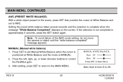
... the cursor is positioned at White Balance and the mode is MANUAL. 2. Note : To avoid failure of the AWC mode setting, do not move the camera or object until the "white balance completed" message appears. MANUAL WHITE BALANCE Red 00 Blue 00 Press SET to Main Menu Gain level is from...
... the cursor is positioned at White Balance and the mode is MANUAL. 2. Note : To avoid failure of the AWC mode setting, do not move the camera or object until the "white balance completed" message appears. MANUAL WHITE BALANCE Red 00 Blue 00 Press SET to Main Menu Gain level is from...

User Manual
Page 24
... Menu End HCMU000878 12/29/03 ERATION menu and pressing SET. 2. Use the left or right button for L.L (line-lock) mode. 3. Sync Mode 1. REV. B 24 Camera 1 to the MAIN MENU. Position the cursor at SYNC MODE and press the left , right, up, and down buttons to move text location. 3. Press the...
... Menu End HCMU000878 12/29/03 ERATION menu and pressing SET. 2. Use the left or right button for L.L (line-lock) mode. 3. Sync Mode 1. REV. B 24 Camera 1 to the MAIN MENU. Position the cursor at SYNC MODE and press the left , right, up, and down buttons to move text location. 3. Press the...

User Manual
Page 25
... PHASE ➔ Phase 135 degree Press SET to the MAIN MENU. MAIN MENU, CONTINUED LINE LOCK PHASE ADJUSTMENT 1. Note : In the line-lock setting, the camera's vertical synchronization can be driven by the 60Hz AC (50Hz PAL) signal in the power lines. • In the line-lock mode, synchronization may not...
... PHASE ➔ Phase 135 degree Press SET to the MAIN MENU. MAIN MENU, CONTINUED LINE LOCK PHASE ADJUSTMENT 1. Note : In the line-lock setting, the camera's vertical synchronization can be driven by the 60Hz AC (50Hz PAL) signal in the power lines. • In the line-lock mode, synchronization may not...

User Manual
Page 31
... conditions as set by the factory. 1. Position the cursor at Preset and press SET. MAIN MENU, CONTINUED Preset The Preset function is useful when the camera setup conditions are frequently changed. SPECIAL MENU Gamma Color Adj Day/Night : Auto Sharpness : LOW Contrast : OFF Brightness ➔ Preset End End To exit the...
... conditions as set by the factory. 1. Position the cursor at Preset and press SET. MAIN MENU, CONTINUED Preset The Preset function is useful when the camera setup conditions are frequently changed. SPECIAL MENU Gamma Color Adj Day/Night : Auto Sharpness : LOW Contrast : OFF Brightness ➔ Preset End End To exit the...

User Manual
Page 33
Connect the lens cable of camera. REV. LENS INSTALLATION AND ADJUSTMENT, CONTINUED DC type lens ; Damping coil (-) Drive coil (+) 1 3 Damping coil (+) 2 4 Pin Assignment : DC type (4-pin) Drive coil (-) 1 3 Pin No. Set ...
Connect the lens cable of camera. REV. LENS INSTALLATION AND ADJUSTMENT, CONTINUED DC type lens ; Damping coil (-) Drive coil (+) 1 3 Damping coil (+) 2 4 Pin Assignment : DC type (4-pin) Drive coil (-) 1 3 Pin No. Set ...
User Manual
Page 34
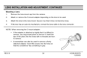
... or remove the C-mount adapter depending on the lens to grip. LENS INSTALLATION AND ADJUSTMENT, CONTINUED Mounting a Lens 1. Remove the lens mount cap from the camera. 2. REV.
... or remove the C-mount adapter depending on the lens to grip. LENS INSTALLATION AND ADJUSTMENT, CONTINUED Mounting a Lens 1. Remove the lens mount cap from the camera. 2. REV.

