

Owner's Manual
Page 1
CT70 Heat Pump Thermostat Wiring Guide 1
CT70 Heat Pump Thermostat Wiring Guide 1
Owner's Manual
Page 3
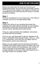
...the back of the thermostat and is usually stamped on your existing thermostat coincide with the thermostat. Before you call Honeywell Customer Assistance toll free at 1-800-468-1502, Monday-Friday, 7:00 a.m. - 5:30 p.m. for example, 9346. 3 Central time, to be sure this thermostat to control your heat... manufacturer, and number of Contents, and turn to the thermostat. HOW TO USE THIS GUIDE Before you disconnect the wires and remove your existing thermostat, be sure you can safely use this new thermostat, see the CT70 wiring hookup diagram, will replace it and that , proceed...
...the back of the thermostat and is usually stamped on your existing thermostat coincide with the thermostat. Before you call Honeywell Customer Assistance toll free at 1-800-468-1502, Monday-Friday, 7:00 a.m. - 5:30 p.m. for example, 9346. 3 Central time, to be sure this thermostat to control your heat... manufacturer, and number of Contents, and turn to the thermostat. HOW TO USE THIS GUIDE Before you disconnect the wires and remove your existing thermostat, be sure you can safely use this new thermostat, see the CT70 wiring hookup diagram, will replace it and that , proceed...

Owner's Manual
Page 6
HEAT light on your thermostat. 6 HEAT PUMPS ARE DIFFERENT Heat pump systems usually have a supplemental, Second Stage heating system that operates only when necessary. This heat pump thermostat is designed to minimize more expensive secondstage operation, indicated by the green AUX.
HEAT light on your thermostat. 6 HEAT PUMPS ARE DIFFERENT Heat pump systems usually have a supplemental, Second Stage heating system that operates only when necessary. This heat pump thermostat is designed to minimize more expensive secondstage operation, indicated by the green AUX.

Owner's Manual
Page 7
... from the auxiliary heat system. OUTDOORS SEVERE WEATHER INDOORS OUTDOOR AIR AUXILIARY HEATING ELEMENT ON INDOOR AIR HEAT TRANSFER M9078 During high heat demand, the thermostat will call for heat in buildings can be unable to deliver enough heat to operate than the compressor. As the air becomes colder outside, the...
... from the auxiliary heat system. OUTDOORS SEVERE WEATHER INDOORS OUTDOOR AIR AUXILIARY HEATING ELEMENT ON INDOOR AIR HEAT TRANSFER M9078 During high heat demand, the thermostat will call for heat in buildings can be unable to deliver enough heat to operate than the compressor. As the air becomes colder outside, the...

Owner's Manual
Page 9
... pumps have the ability to indicate when the heat pump is not connected to the power side of the 24-volt transformer. On your original thermostat, this terminal was activated by an outdoor sensor that is activated and the EM. position. HEAT LOADS: This terminal is on. Because the... CT70 only has provisions for one auxiliary heat load, these loads must be connected to the common side of the 24-volt transformer. FAN: When this ...
... pumps have the ability to indicate when the heat pump is not connected to the power side of the 24-volt transformer. On your original thermostat, this terminal was activated by an outdoor sensor that is activated and the EM. position. HEAT LOADS: This terminal is on. Because the... CT70 only has provisions for one auxiliary heat load, these loads must be connected to the common side of the 24-volt transformer. FAN: When this ...

Owner's Manual
Page 11
Jumper these two terminals if both are present # This terminal must be connected to transformer common. $ Remove this factory-installed jumper for independent stage 1 heat and cool connection. 11 HEAT SYSTEM MONITOR Existing thermostat wiring X1 or C 1 R or RC or RH Y or Y1 W1 W2 G B or W O E AMANA New thermostat wiring 2 X R Y1 3 W1 W2 G B O E L ! HEAT FAN C/O VALVE HEAT C/O VALVE COOL EM. Wiring terminal function COMMON POWER COMPRESSOR 1ST STG. HEAT AUX.
Jumper these two terminals if both are present # This terminal must be connected to transformer common. $ Remove this factory-installed jumper for independent stage 1 heat and cool connection. 11 HEAT SYSTEM MONITOR Existing thermostat wiring X1 or C 1 R or RC or RH Y or Y1 W1 W2 G B or W O E AMANA New thermostat wiring 2 X R Y1 3 W1 W2 G B O E L ! HEAT FAN C/O VALVE HEAT C/O VALVE COOL EM. Wiring terminal function COMMON POWER COMPRESSOR 1ST STG. HEAT AUX.

Owner's Manual
Page 12
HEAT W2 FAN G C/O VALVE HEAT 4 B or W1 C/O VALVE COOL 4O SYSTEM MONITOR L EM. BARD/JANITROL/TAPPAN/WILLIAMSON Wiring terminal function COMMON Existing thermostat wiring 1 C or X1 or X POWER RH or RC or R COMPRESSOR Y 1ST STG. This terminal must be connected to transformer common. # Leave factory-installed jumper in place. $ Connect multiple second stage heating loads to W2 terminals. % Thermostat is connected to either O or B terminal, but not both. 12 HEAT LOADS 3 W3 New thermostat wiring 1 X R Y1 2 W1 W2 G B O L E 3 ! HEAT E MULTIPLE AUX. HEAT AUX.
HEAT W2 FAN G C/O VALVE HEAT 4 B or W1 C/O VALVE COOL 4O SYSTEM MONITOR L EM. BARD/JANITROL/TAPPAN/WILLIAMSON Wiring terminal function COMMON Existing thermostat wiring 1 C or X1 or X POWER RH or RC or R COMPRESSOR Y 1ST STG. This terminal must be connected to transformer common. # Leave factory-installed jumper in place. $ Connect multiple second stage heating loads to W2 terminals. % Thermostat is connected to either O or B terminal, but not both. 12 HEAT LOADS 3 W3 New thermostat wiring 1 X R Y1 2 W1 W2 G B O L E 3 ! HEAT E MULTIPLE AUX. HEAT AUX.

Owner's Manual
Page 13
HEAT AUX. ARCOAIRE/SNYDER GENERAL/COMFORTMAKER Wiring terminal function COMMON POWER COMPRESSOR 1ST STG. HEAT FAN C/O VALVE HEAT C/O VALVE COOL SYSTEM MONITOR EM. HEAT Existing thermostat wiring 1 X,X1 or C R Y W2 or W1 G O L or X E New thermostat wiring 1 X R Y1 2 W1 W2 G B O L E ! This terminal must be connected to transformer common. # Leave factory-installed jumper in place. 13
HEAT AUX. ARCOAIRE/SNYDER GENERAL/COMFORTMAKER Wiring terminal function COMMON POWER COMPRESSOR 1ST STG. HEAT FAN C/O VALVE HEAT C/O VALVE COOL SYSTEM MONITOR EM. HEAT Existing thermostat wiring 1 X,X1 or C R Y W2 or W1 G O L or X E New thermostat wiring 1 X R Y1 2 W1 W2 G B O L E ! This terminal must be connected to transformer common. # Leave factory-installed jumper in place. 13

Owner's Manual
Page 14
HEAT MULTIPLE AUX. HEAT LOADS 3 DEFROST Existing thermostat wiring C1 or X1 or C 1 R W1 or Y W2 G B Y1 or O L or F X or E W3 P New thermostat wiring 1 X R Y1 2 W1 W2 G B 3 O L E P ! This terminal must be connected to transformer common. # Leave factory-installed jumper in place. $ Connect multiple second stage heating loads to W2 terminals. 14 HEAT FAN C/O VALVE HEAT C/O VALVE COOL SYSTEM MONITOR EM. HEAT AUX. B.D.P. (BRYANT-DAY/NIGHT-PAYNE) Wiring terminal function COMMON POWER COMPRESSOR 1ST STG.
HEAT MULTIPLE AUX. HEAT LOADS 3 DEFROST Existing thermostat wiring C1 or X1 or C 1 R W1 or Y W2 G B Y1 or O L or F X or E W3 P New thermostat wiring 1 X R Y1 2 W1 W2 G B 3 O L E P ! This terminal must be connected to transformer common. # Leave factory-installed jumper in place. $ Connect multiple second stage heating loads to W2 terminals. 14 HEAT FAN C/O VALVE HEAT C/O VALVE COOL SYSTEM MONITOR EM. HEAT AUX. B.D.P. (BRYANT-DAY/NIGHT-PAYNE) Wiring terminal function COMMON POWER COMPRESSOR 1ST STG.

Owner's Manual
Page 15
HEAT FAN C/O VALVE HEAT C/O VALVE COOL SYSTEM MONITOR EM. HEAT AUX. This terminal must be connected to transformer common. # Leave factory-installed jumper in place. 15 HEAT Existing thermostat wiring 1 C R Y W1 or W2 G O F or L E CARRIER New thermostat wiring 1 X R Y1 2 W1 W2 G B O L E ! Wiring terminal function COMMON POWER COMPRESSOR 1ST STG.
HEAT FAN C/O VALVE HEAT C/O VALVE COOL SYSTEM MONITOR EM. HEAT AUX. This terminal must be connected to transformer common. # Leave factory-installed jumper in place. 15 HEAT Existing thermostat wiring 1 C R Y W1 or W2 G O F or L E CARRIER New thermostat wiring 1 X R Y1 2 W1 W2 G B O L E ! Wiring terminal function COMMON POWER COMPRESSOR 1ST STG.
Owner's Manual
Page 16
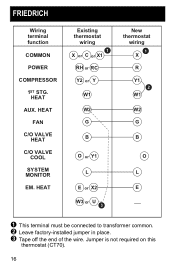
FRIEDRICH Wiring terminal function COMMON POWER COMPRESSOR 1ST STG. HEAT Existing thermostat wiring 1 X or C or X1 RH or RC Y2 or Y W1 W2 G B O or Y1 L E or X2 W3 or U 3 New thermostat wiring 1 X R Y1 2 W1 W2 G B O L E ! This terminal must be connected to transformer common. # Leave factory-installed jumper in place. $ Tape off the end of the wire. HEAT AUX. HEAT FAN C/O VALVE HEAT C/O VALVE COOL SYSTEM MONITOR EM. Jumper is not required on this thermostat (CT70). 16
FRIEDRICH Wiring terminal function COMMON POWER COMPRESSOR 1ST STG. HEAT Existing thermostat wiring 1 X or C or X1 RH or RC Y2 or Y W1 W2 G B O or Y1 L E or X2 W3 or U 3 New thermostat wiring 1 X R Y1 2 W1 W2 G B O L E ! This terminal must be connected to transformer common. # Leave factory-installed jumper in place. $ Tape off the end of the wire. HEAT AUX. HEAT FAN C/O VALVE HEAT C/O VALVE COOL SYSTEM MONITOR EM. Jumper is not required on this thermostat (CT70). 16

Owner's Manual
Page 17
HEAT FAN C/O VALVE HEAT C/O VALVE COOL SYSTEM MONITOR EM. This terminal must be connected to transformer common. # Leave factory-installed jumper in place. 17 HEIL QUAKER/WHIRLPOOL/TEMPSTAR Wiring terminal function COMMON POWER COMPRESSOR 1ST STG. HEAT AUX. HEAT Existing thermostat wiring C or B R Y W G B O X New thermostat wiring 1 X R Y1 2 W1 W2 G B O L E !
HEAT FAN C/O VALVE HEAT C/O VALVE COOL SYSTEM MONITOR EM. This terminal must be connected to transformer common. # Leave factory-installed jumper in place. 17 HEIL QUAKER/WHIRLPOOL/TEMPSTAR Wiring terminal function COMMON POWER COMPRESSOR 1ST STG. HEAT AUX. HEAT Existing thermostat wiring C or B R Y W G B O X New thermostat wiring 1 X R Y1 2 W1 W2 G B O L E !

Owner's Manual
Page 18
HEAT (COMP) 1ST STG. COOL 2ND STG. HEAT Existing thermostat wiring Y or X BL or V/VR R or M O or Y Y or F BK or R E New thermostat wiring 1 X R W1 Y1 2 W2 G B O L E ! LENNOX Wiring terminal function COMMON POWER 1ST STG. HEAT FAN C/O VALVE HEAT C/O VALVE COOL SYSTEM MONITOR EM. This terminal must be connected to transformer common. # Leave factory-installed jumper in place. 18
HEAT (COMP) 1ST STG. COOL 2ND STG. HEAT Existing thermostat wiring Y or X BL or V/VR R or M O or Y Y or F BK or R E New thermostat wiring 1 X R W1 Y1 2 W2 G B O L E ! LENNOX Wiring terminal function COMMON POWER 1ST STG. HEAT FAN C/O VALVE HEAT C/O VALVE COOL SYSTEM MONITOR EM. This terminal must be connected to transformer common. # Leave factory-installed jumper in place. 18

Owner's Manual
Page 19
HEAT FAN C/O VALVE HEAT C/O VALVE COOL SYSTEM MONITOR EM. HEAT Existing thermostat wiring 1 X R Y W2 G B O L E RHEEM/RUUD New thermostat wiring 1 X R Y1 2 W1 W2 G B O L E ! This terminal must be connected to transformer common. # Leave factory-installed jumper in place. 19 Wiring terminal function COMMON POWER COMPRESSOR 1ST STG. HEAT AUX.
HEAT FAN C/O VALVE HEAT C/O VALVE COOL SYSTEM MONITOR EM. HEAT Existing thermostat wiring 1 X R Y W2 G B O L E RHEEM/RUUD New thermostat wiring 1 X R Y1 2 W1 W2 G B O L E ! This terminal must be connected to transformer common. # Leave factory-installed jumper in place. 19 Wiring terminal function COMMON POWER COMPRESSOR 1ST STG. HEAT AUX.

Owner's Manual
Page 20
This terminal must be connected to transformer common. # Leave factory-installed jumper in place. $ Tape off end. TRANE/AMERICAN STANDARD Wiring terminal function COMMON POWER 1ST STG. HEAT FAN C/O VALVE HEAT C/O VALVE COOL SYSTEM MONITOR OUTDOOR SENSOR OUTDOOR STAT Existing thermostat wiring 1 B R Y W1 or W G O F or L T W2 or X2 New thermostat wiring 1 X R W1 2 Y1 W2 G B O L 3 E ! CT70 replaces outdoor reset with improved zero droop performance. 20 HEAT AUX.
This terminal must be connected to transformer common. # Leave factory-installed jumper in place. $ Tape off end. TRANE/AMERICAN STANDARD Wiring terminal function COMMON POWER 1ST STG. HEAT FAN C/O VALVE HEAT C/O VALVE COOL SYSTEM MONITOR OUTDOOR SENSOR OUTDOOR STAT Existing thermostat wiring 1 B R Y W1 or W G O F or L T W2 or X2 New thermostat wiring 1 X R W1 2 Y1 W2 G B O L 3 E ! CT70 replaces outdoor reset with improved zero droop performance. 20 HEAT AUX.

Owner's Manual
Page 21
This terminal must be connected to transformer common. # Connect multiple second stage heating loads to W2 terminals. $ Leave factory-installed jumper in place. % If present on original equipment. 21 HEAT MULTIPLE AUX. YORK/BORG WARNER/LUXAIRE (MONCRIEF, FRASER-JOHNSTON) Wiring terminal function COMMON POWER COMPRESSOR 1ST STG. HEAT LOADS Existing thermostat wiring X or B R Y W or W2 G H O 4 X or L 4 E 4 W3 New thermostat wiring 1 X R Y1 3 W1 W2 G B O L E 2 ! HEAT AUX. HEAT FAN C/O VALVE HEAT C/O VALVE COOL SYSTEM MONITOR EM.
This terminal must be connected to transformer common. # Connect multiple second stage heating loads to W2 terminals. $ Leave factory-installed jumper in place. % If present on original equipment. 21 HEAT MULTIPLE AUX. YORK/BORG WARNER/LUXAIRE (MONCRIEF, FRASER-JOHNSTON) Wiring terminal function COMMON POWER COMPRESSOR 1ST STG. HEAT LOADS Existing thermostat wiring X or B R Y W or W2 G H O 4 X or L 4 E 4 W3 New thermostat wiring 1 X R Y1 3 W1 W2 G B O L E 2 ! HEAT AUX. HEAT FAN C/O VALVE HEAT C/O VALVE COOL SYSTEM MONITOR EM.

Owner's Manual
Page 22
This terminal must be connected to transformer common. # Remove factory-installed jumper. 22 HEAT Existing thermostat wiring B or X2 R W1 W2 G Y1 E New thermostat wiring 1 X R W1 W2 G 2 Y1 B O L E ! HEAT FAN 1ST STG. COOL C/O VALVE HEAT C/O VALVE COOL SYSTEM MONITOR EM. YORK/BORG WARNER Wiring terminal function COMMON POWER 1ST STG. HEAT AUX.
This terminal must be connected to transformer common. # Remove factory-installed jumper. 22 HEAT Existing thermostat wiring B or X2 R W1 W2 G Y1 E New thermostat wiring 1 X R W1 W2 G 2 Y1 B O L E ! HEAT FAN 1ST STG. COOL C/O VALVE HEAT C/O VALVE COOL SYSTEM MONITOR EM. YORK/BORG WARNER Wiring terminal function COMMON POWER 1ST STG. HEAT AUX.


