Honeywell CT70 Support and Manuals
Get Help and Manuals for this Honeywell item

View All Support Options Below
Free Honeywell CT70 manuals!
Problems with Honeywell CT70?
Ask a Question
Free Honeywell CT70 manuals!
Problems with Honeywell CT70?
Ask a Question
Popular Honeywell CT70 Manual Pages
Owner's Manual - Page 1

CT70
Heat Pump Thermostat Wiring Guide
1
Owner's Manual - Page 3
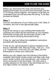
... sure you can safely use this new thermostat, see the CT70 wiring hookup diagram, will replace it and that you understand how you call Honeywell Customer Assistance toll free at 1-800-468-1502, Monday-Friday, 7:00 a.m. - 5:30 p.m.
The date code is a four-digit number; If they do, read and follow the installation instructions provided with the terminals shown in...
Owner's Manual - Page 10

... JUMPER WHEN HEAT RELAY 1 IS USED. 3 WHEN L TERMINAL IS CONNECTED TO SYSTEM MONITOR, EM. HEAT RELAY
HEAT RELAY 1
COMPRESSOR CONTACTOR
1 POWER SUPPLY. M8504
Typical wiring hookup of CT70 with jumper intact.
10 HEAT RELAY
FAN RELAY
CHANGEOVER RELAY (HEAT)
4X L
B
W2 3
R
2 W1 E
G O Y1
EM. CHANGEOVER RELAY (COOL)
L1 (HOT) L2
1
SYSTEM MONITOR...
Owner's Manual - Page 11

...
C/O VALVE COOL
EM. HEAT
SYSTEM MONITOR
Existing thermostat
wiring X1 or C
1 R or RC or RH
Y or Y1
W1
W2 G
B or W
O
E
AMANA
New thermostat
wiring
2 X R Y1
3 W1
W2 G
B
O
E
L
! HEAT
AUX. Jumper these two terminals if both are present # This terminal must be connected to transformer common. $ Remove this factory-installed jumper for independent stage 1
heat and...
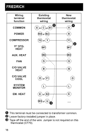
Owner's Manual - Page 12

.... This terminal must be connected to transformer common. # Leave factory-installed jumper in place. $ Connect multiple second stage heating loads to W2 terminals. % Thermostat is connected to either O or B terminal, but not
both. 12 BARD/JANITROL/TAPPAN/WILLIAMSON
Wiring terminal function
COMMON
Existing thermostat
wiring
1 C or X1 or X
POWER
RH or RC or R
COMPRESSOR
Y
1ST...
Owner's Manual - Page 13

ARCOAIRE/SNYDER GENERAL/COMFORTMAKER
Wiring terminal function
COMMON
POWER
COMPRESSOR
1ST STG. HEAT
FAN
C/O VALVE HEAT
C/O VALVE COOL
SYSTEM MONITOR
EM. This terminal must be connected to transformer common. # Leave factory-installed jumper in place.
13 HEAT
AUX. HEAT
Existing thermostat
wiring
1 X,X1 or C
R Y
W2 or W1 G
O L or X
E
New thermostat
wiring
1 X R Y1
2 W1
W2 G
B
O
L
E
!
Owner's Manual - Page 14

... Y
W2 G B
Y1 or O
L or F X or E
W3 P
New thermostat
wiring
1 X R Y1
2 W1
W2 G
B 3
O
L
E
P
! This terminal must be connected to transformer common. # Leave factory-installed jumper in place. $ Connect multiple second stage heating loads to W2 terminals.
14 HEAT
AUX. HEAT
MULTIPLE AUX. B.D.P. (BRYANT-DAY/NIGHT-PAYNE)
Wiring terminal function
COMMON
POWER
COMPRESSOR
1ST STG. HEAT...
Owner's Manual - Page 15

Wiring terminal function
COMMON
POWER
COMPRESSOR
1ST STG. HEAT
FAN
C/O VALVE HEAT
C/O VALVE COOL
SYSTEM MONITOR
EM. This terminal must be connected to transformer common. # Leave factory-installed jumper in place.
15 HEAT
Existing thermostat
wiring
1 C R Y
W1 or W2 G
O F or L
E
CARRIER
New thermostat
wiring
1 X R Y1
2 W1
W2 G
B
O
L
E
! HEAT
AUX.
Owner's Manual - Page 16
...
RH or RC Y2 or Y
W1
W2 G
B
O or Y1
L
E or X2 W3 or U
3
New thermostat
wiring
1 X R Y1
2 W1
W2 G
B
O
L
E
! This terminal must be connected to transformer common. # Leave factory-installed jumper in place. $ Tape off the end of the wire. HEAT
FAN
C/O VALVE HEAT
C/O VALVE COOL
SYSTEM MONITOR
EM. HEAT
AUX. Jumper is not...
Owner's Manual - Page 17

HEAT
Existing thermostat
wiring C or B
R Y
W G B O
X
New thermostat
wiring
1 X R Y1
2 W1
W2 G
B
O
L
E
! This terminal must be connected to transformer common. # Leave factory-installed jumper in place.
17 HEAT
FAN
C/O VALVE HEAT
C/O VALVE COOL
SYSTEM MONITOR
EM. HEAT
AUX. HEIL QUAKER/WHIRLPOOL/TEMPSTAR
Wiring terminal function
COMMON
POWER
COMPRESSOR
1ST STG.
Owner's Manual - Page 18

HEAT
FAN
C/O VALVE HEAT
C/O VALVE COOL
SYSTEM MONITOR
EM. COOL
2ND STG. This terminal must be connected to transformer common. # Leave factory-installed jumper in place.
18 HEAT
Existing thermostat
wiring Y or X BL or V/VR R or M
O or Y Y or F
BK or R
E
New thermostat
wiring
1 X R W1
Y1 2
W2
G B
O
L E
! LENNOX
Wiring terminal function
COMMON
POWER
1ST STG. HEAT (COMP)
1ST STG.
Owner's Manual - Page 19

This terminal must be connected to transformer common. # Leave factory-installed jumper in place.
19 HEAT
AUX. HEAT
FAN
C/O VALVE HEAT
C/O VALVE COOL
SYSTEM MONITOR
EM. Wiring terminal function
COMMON
POWER
COMPRESSOR
1ST STG. HEAT
Existing thermostat
wiring
1 X R Y
W2 G B
O
L E
RHEEM/RUUD
New thermostat
wiring
1 X R Y1
2 W1
W2 G
B
O
L
E
!
Owner's Manual - Page 20

.... # Leave factory-installed jumper in place. $ Tape off end. TRANE/AMERICAN STANDARD
Wiring terminal function
COMMON
POWER
1ST STG. HEAT
AUX. CT70 replaces outdoor reset with improved zero
droop performance. 20 HEAT
FAN
C/O VALVE HEAT
C/O VALVE COOL
SYSTEM MONITOR
OUTDOOR SENSOR
OUTDOOR STAT
Existing thermostat
wiring
1 B R
Y W1 or W
G
O F or L
T W2 or X2
New thermostat
wiring
1 X R W1
2 Y1...
Owner's Manual - Page 21

HEAT LOADS
Existing thermostat
wiring X or B
R Y
W or W2 G
H
O 4
X or L 4
E 4
W3
New thermostat
wiring
1 X R Y1
3 W1
W2 G
B
O
L
E
2
! This terminal must be connected to transformer common. # Connect multiple second stage heating loads to W2 terminals. $ Leave factory-installed jumper in place. % If present on original equipment.
21 HEAT
MULTIPLE AUX. HEAT
AUX. HEAT
FAN
C/O VALVE HEAT
...
Owner's Manual - Page 22

COOL
C/O VALVE HEAT
C/O VALVE COOL
SYSTEM MONITOR
EM. This terminal must be connected to transformer common. # Remove factory-installed jumper.
22 HEAT
Existing thermostat
wiring B or X2
R W1 W2 G Y1
E
New thermostat
wiring
1 X R
W1
W2 G
2 Y1
B
O
L
E
! YORK/BORG WARNER
Wiring terminal function
COMMON
POWER
1ST STG. HEAT
AUX. HEAT
FAN
1ST STG.
Honeywell CT70 Reviews
We have not received any reviews for Honeywell yet.