
Owner's Manual
Page 3
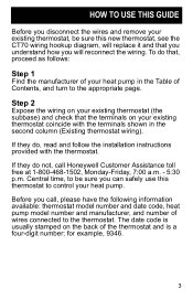
... of wires connected to control your heat pump. Step 2 Expose the wiring on your existing thermostat (the subbase) and check that you understand how you will reconnect the wiring. Before you call Honeywell Customer Assistance toll free at 1-800-468-1502, Monday-Friday, 7:00 a.m. - 5:30 ...new thermostat, see the CT70 wiring hookup diagram, will replace it and that the terminals on the back of the thermostat and is a four-digit number; The date code is usually stamped on your existing thermostat coincide with the thermostat. If they do , read and follow the installation instructions...
... of wires connected to control your heat pump. Step 2 Expose the wiring on your existing thermostat (the subbase) and check that you understand how you will reconnect the wiring. Before you call Honeywell Customer Assistance toll free at 1-800-468-1502, Monday-Friday, 7:00 a.m. - 5:30 ...new thermostat, see the CT70 wiring hookup diagram, will replace it and that the terminals on the back of the thermostat and is a four-digit number; The date code is usually stamped on your existing thermostat coincide with the thermostat. If they do , read and follow the installation instructions...

Owner's Manual
Page 11
HEAT FAN C/O VALVE HEAT C/O VALVE COOL EM. Jumper these two terminals if both are present # This terminal must be connected to transformer common. $ Remove this factory-installed jumper for independent stage 1 heat and cool connection. 11 HEAT SYSTEM MONITOR Existing thermostat wiring X1 or C 1 R or RC or RH Y or Y1 W1 W2 G B or W O E AMANA New thermostat wiring 2 X R Y1 3 W1 W2 G B O E L ! Wiring terminal function COMMON POWER COMPRESSOR 1ST STG. HEAT AUX.
HEAT FAN C/O VALVE HEAT C/O VALVE COOL EM. Jumper these two terminals if both are present # This terminal must be connected to transformer common. $ Remove this factory-installed jumper for independent stage 1 heat and cool connection. 11 HEAT SYSTEM MONITOR Existing thermostat wiring X1 or C 1 R or RC or RH Y or Y1 W1 W2 G B or W O E AMANA New thermostat wiring 2 X R Y1 3 W1 W2 G B O E L ! Wiring terminal function COMMON POWER COMPRESSOR 1ST STG. HEAT AUX.

Owner's Manual
Page 12
This terminal must be connected to transformer common. # Leave factory-installed jumper in place. $ Connect multiple second stage heating loads to W2 terminals. % Thermostat is connected to either O or B terminal, but not both. 12 HEAT W2 FAN G C/O VALVE HEAT 4 B or W1 C/O VALVE COOL 4O SYSTEM MONITOR L EM. HEAT LOADS 3 W3 New thermostat wiring 1 X R Y1 2 W1 W2 G B O L E 3 ! HEAT AUX. HEAT E MULTIPLE AUX. BARD/JANITROL/TAPPAN/WILLIAMSON Wiring terminal function COMMON Existing thermostat wiring 1 C or X1 or X POWER RH or RC or R COMPRESSOR Y 1ST STG.
This terminal must be connected to transformer common. # Leave factory-installed jumper in place. $ Connect multiple second stage heating loads to W2 terminals. % Thermostat is connected to either O or B terminal, but not both. 12 HEAT W2 FAN G C/O VALVE HEAT 4 B or W1 C/O VALVE COOL 4O SYSTEM MONITOR L EM. HEAT LOADS 3 W3 New thermostat wiring 1 X R Y1 2 W1 W2 G B O L E 3 ! HEAT AUX. HEAT E MULTIPLE AUX. BARD/JANITROL/TAPPAN/WILLIAMSON Wiring terminal function COMMON Existing thermostat wiring 1 C or X1 or X POWER RH or RC or R COMPRESSOR Y 1ST STG.

Owner's Manual
Page 13
HEAT FAN C/O VALVE HEAT C/O VALVE COOL SYSTEM MONITOR EM. ARCOAIRE/SNYDER GENERAL/COMFORTMAKER Wiring terminal function COMMON POWER COMPRESSOR 1ST STG. HEAT Existing thermostat wiring 1 X,X1 or C R Y W2 or W1 G O L or X E New thermostat wiring 1 X R Y1 2 W1 W2 G B O L E ! This terminal must be connected to transformer common. # Leave factory-installed jumper in place. 13 HEAT AUX.
HEAT FAN C/O VALVE HEAT C/O VALVE COOL SYSTEM MONITOR EM. ARCOAIRE/SNYDER GENERAL/COMFORTMAKER Wiring terminal function COMMON POWER COMPRESSOR 1ST STG. HEAT Existing thermostat wiring 1 X,X1 or C R Y W2 or W1 G O L or X E New thermostat wiring 1 X R Y1 2 W1 W2 G B O L E ! This terminal must be connected to transformer common. # Leave factory-installed jumper in place. 13 HEAT AUX.

Owner's Manual
Page 14
HEAT AUX. HEAT FAN C/O VALVE HEAT C/O VALVE COOL SYSTEM MONITOR EM. HEAT MULTIPLE AUX. HEAT LOADS 3 DEFROST Existing thermostat wiring C1 or X1 or C 1 R W1 or Y W2 G B Y1 or O L or F X or E W3 P New thermostat wiring 1 X R Y1 2 W1 W2 G B 3 O L E P ! B.D.P. (BRYANT-DAY/NIGHT-PAYNE) Wiring terminal function COMMON POWER COMPRESSOR 1ST STG. This terminal must be connected to transformer common. # Leave factory-installed jumper in place. $ Connect multiple second stage heating loads to W2 terminals. 14
HEAT AUX. HEAT FAN C/O VALVE HEAT C/O VALVE COOL SYSTEM MONITOR EM. HEAT MULTIPLE AUX. HEAT LOADS 3 DEFROST Existing thermostat wiring C1 or X1 or C 1 R W1 or Y W2 G B Y1 or O L or F X or E W3 P New thermostat wiring 1 X R Y1 2 W1 W2 G B 3 O L E P ! B.D.P. (BRYANT-DAY/NIGHT-PAYNE) Wiring terminal function COMMON POWER COMPRESSOR 1ST STG. This terminal must be connected to transformer common. # Leave factory-installed jumper in place. $ Connect multiple second stage heating loads to W2 terminals. 14

Owner's Manual
Page 15
Wiring terminal function COMMON POWER COMPRESSOR 1ST STG. HEAT AUX. This terminal must be connected to transformer common. # Leave factory-installed jumper in place. 15 HEAT FAN C/O VALVE HEAT C/O VALVE COOL SYSTEM MONITOR EM. HEAT Existing thermostat wiring 1 C R Y W1 or W2 G O F or L E CARRIER New thermostat wiring 1 X R Y1 2 W1 W2 G B O L E !
Wiring terminal function COMMON POWER COMPRESSOR 1ST STG. HEAT AUX. This terminal must be connected to transformer common. # Leave factory-installed jumper in place. 15 HEAT FAN C/O VALVE HEAT C/O VALVE COOL SYSTEM MONITOR EM. HEAT Existing thermostat wiring 1 C R Y W1 or W2 G O F or L E CARRIER New thermostat wiring 1 X R Y1 2 W1 W2 G B O L E !
Owner's Manual
Page 16
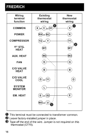
This terminal must be connected to transformer common. # Leave factory-installed jumper in place. $ Tape off the end of the wire. HEAT Existing thermostat wiring 1 X or C or X1 RH or RC Y2 or Y W1 W2 G B O or Y1 L E or X2 W3 or U 3 New thermostat wiring 1 X R Y1 2 W1 W2 G B O L E ! HEAT FAN C/O VALVE HEAT C/O VALVE COOL SYSTEM MONITOR EM. HEAT AUX. FRIEDRICH Wiring terminal function COMMON POWER COMPRESSOR 1ST STG. Jumper is not required on this thermostat (CT70). 16
This terminal must be connected to transformer common. # Leave factory-installed jumper in place. $ Tape off the end of the wire. HEAT Existing thermostat wiring 1 X or C or X1 RH or RC Y2 or Y W1 W2 G B O or Y1 L E or X2 W3 or U 3 New thermostat wiring 1 X R Y1 2 W1 W2 G B O L E ! HEAT FAN C/O VALVE HEAT C/O VALVE COOL SYSTEM MONITOR EM. HEAT AUX. FRIEDRICH Wiring terminal function COMMON POWER COMPRESSOR 1ST STG. Jumper is not required on this thermostat (CT70). 16

Owner's Manual
Page 17
HEAT Existing thermostat wiring C or B R Y W G B O X New thermostat wiring 1 X R Y1 2 W1 W2 G B O L E ! This terminal must be connected to transformer common. # Leave factory-installed jumper in place. 17 HEAT FAN C/O VALVE HEAT C/O VALVE COOL SYSTEM MONITOR EM. HEAT AUX. HEIL QUAKER/WHIRLPOOL/TEMPSTAR Wiring terminal function COMMON POWER COMPRESSOR 1ST STG.
HEAT Existing thermostat wiring C or B R Y W G B O X New thermostat wiring 1 X R Y1 2 W1 W2 G B O L E ! This terminal must be connected to transformer common. # Leave factory-installed jumper in place. 17 HEAT FAN C/O VALVE HEAT C/O VALVE COOL SYSTEM MONITOR EM. HEAT AUX. HEIL QUAKER/WHIRLPOOL/TEMPSTAR Wiring terminal function COMMON POWER COMPRESSOR 1ST STG.

Owner's Manual
Page 18
LENNOX Wiring terminal function COMMON POWER 1ST STG. COOL 2ND STG. This terminal must be connected to transformer common. # Leave factory-installed jumper in place. 18 HEAT Existing thermostat wiring Y or X BL or V/VR R or M O or Y Y or F BK or R E New thermostat wiring 1 X R W1 Y1 2 W2 G B O L E ! HEAT FAN C/O VALVE HEAT C/O VALVE COOL SYSTEM MONITOR EM. HEAT (COMP) 1ST STG.
LENNOX Wiring terminal function COMMON POWER 1ST STG. COOL 2ND STG. This terminal must be connected to transformer common. # Leave factory-installed jumper in place. 18 HEAT Existing thermostat wiring Y or X BL or V/VR R or M O or Y Y or F BK or R E New thermostat wiring 1 X R W1 Y1 2 W2 G B O L E ! HEAT FAN C/O VALVE HEAT C/O VALVE COOL SYSTEM MONITOR EM. HEAT (COMP) 1ST STG.

Owner's Manual
Page 19
This terminal must be connected to transformer common. # Leave factory-installed jumper in place. 19 HEAT Existing thermostat wiring 1 X R Y W2 G B O L E RHEEM/RUUD New thermostat wiring 1 X R Y1 2 W1 W2 G B O L E ! Wiring terminal function COMMON POWER COMPRESSOR 1ST STG. HEAT FAN C/O VALVE HEAT C/O VALVE COOL SYSTEM MONITOR EM. HEAT AUX.
This terminal must be connected to transformer common. # Leave factory-installed jumper in place. 19 HEAT Existing thermostat wiring 1 X R Y W2 G B O L E RHEEM/RUUD New thermostat wiring 1 X R Y1 2 W1 W2 G B O L E ! Wiring terminal function COMMON POWER COMPRESSOR 1ST STG. HEAT FAN C/O VALVE HEAT C/O VALVE COOL SYSTEM MONITOR EM. HEAT AUX.

Owner's Manual
Page 20
HEAT AUX. TRANE/AMERICAN STANDARD Wiring terminal function COMMON POWER 1ST STG. HEAT FAN C/O VALVE HEAT C/O VALVE COOL SYSTEM MONITOR OUTDOOR SENSOR OUTDOOR STAT Existing thermostat wiring 1 B R Y W1 or W G O F or L T W2 or X2 New thermostat wiring 1 X R W1 2 Y1 W2 G B O L 3 E ! CT70 replaces outdoor reset with improved zero droop performance. 20 This terminal must be connected to transformer common. # Leave factory-installed jumper in place. $ Tape off end.
HEAT AUX. TRANE/AMERICAN STANDARD Wiring terminal function COMMON POWER 1ST STG. HEAT FAN C/O VALVE HEAT C/O VALVE COOL SYSTEM MONITOR OUTDOOR SENSOR OUTDOOR STAT Existing thermostat wiring 1 B R Y W1 or W G O F or L T W2 or X2 New thermostat wiring 1 X R W1 2 Y1 W2 G B O L 3 E ! CT70 replaces outdoor reset with improved zero droop performance. 20 This terminal must be connected to transformer common. # Leave factory-installed jumper in place. $ Tape off end.

Owner's Manual
Page 21
HEAT LOADS Existing thermostat wiring X or B R Y W or W2 G H O 4 X or L 4 E 4 W3 New thermostat wiring 1 X R Y1 3 W1 W2 G B O L E 2 ! HEAT AUX. HEAT MULTIPLE AUX. This terminal must be connected to transformer common. # Connect multiple second stage heating loads to W2 terminals. $ Leave factory-installed jumper in place. % If present on original equipment. 21 YORK/BORG WARNER/LUXAIRE (MONCRIEF, FRASER-JOHNSTON) Wiring terminal function COMMON POWER COMPRESSOR 1ST STG. HEAT FAN C/O VALVE HEAT C/O VALVE COOL SYSTEM MONITOR EM.
HEAT LOADS Existing thermostat wiring X or B R Y W or W2 G H O 4 X or L 4 E 4 W3 New thermostat wiring 1 X R Y1 3 W1 W2 G B O L E 2 ! HEAT AUX. HEAT MULTIPLE AUX. This terminal must be connected to transformer common. # Connect multiple second stage heating loads to W2 terminals. $ Leave factory-installed jumper in place. % If present on original equipment. 21 YORK/BORG WARNER/LUXAIRE (MONCRIEF, FRASER-JOHNSTON) Wiring terminal function COMMON POWER COMPRESSOR 1ST STG. HEAT FAN C/O VALVE HEAT C/O VALVE COOL SYSTEM MONITOR EM.

Owner's Manual
Page 22
HEAT AUX. This terminal must be connected to transformer common. # Remove factory-installed jumper. 22 COOL C/O VALVE HEAT C/O VALVE COOL SYSTEM MONITOR EM. HEAT FAN 1ST STG. HEAT Existing thermostat wiring B or X2 R W1 W2 G Y1 E New thermostat wiring 1 X R W1 W2 G 2 Y1 B O L E ! YORK/BORG WARNER Wiring terminal function COMMON POWER 1ST STG.
HEAT AUX. This terminal must be connected to transformer common. # Remove factory-installed jumper. 22 COOL C/O VALVE HEAT C/O VALVE COOL SYSTEM MONITOR EM. HEAT FAN 1ST STG. HEAT Existing thermostat wiring B or X2 R W1 W2 G Y1 E New thermostat wiring 1 X R W1 W2 G 2 Y1 B O L E ! YORK/BORG WARNER Wiring terminal function COMMON POWER 1ST STG.


