
Owner's Manual
Page 2
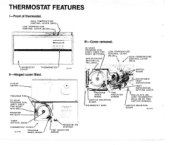
Ill-Cover removed. 24 HOUR PROGRAM DIAL 'THERMOSTAT COVER THERMOMETER 1 11.711 Il-Hinged cover lifted. .. .~ . ,..... . CAPTIVE MOUNTING ANTICIPATOR HIND THERMOSTAT. H E L D O N BY TWO CAPTIVE SCREWS.) HlGH TEMPERATURE 1 CONTROL LEVER (RED) LOW TEMPERATURE CONTROL LEVER (BLUE)- PROGRAM PINS A "--- THERMOSTAT FEATURES I-Front of thermostat.
Ill-Cover removed. 24 HOUR PROGRAM DIAL 'THERMOSTAT COVER THERMOMETER 1 11.711 Il-Hinged cover lifted. .. .~ . ,..... . CAPTIVE MOUNTING ANTICIPATOR HIND THERMOSTAT. H E L D O N BY TWO CAPTIVE SCREWS.) HlGH TEMPERATURE 1 CONTROL LEVER (RED) LOW TEMPERATURE CONTROL LEVER (BLUE)- PROGRAM PINS A "--- THERMOSTAT FEATURES I-Front of thermostat.
Owner's Manual
Page 3
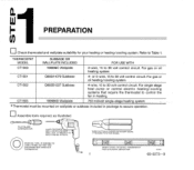
... OISCONNECTED FROM OLD THERMOSTAT CT1502 CT1503 Q682B1227 Subbase 199986D Wailp ate 4-wire, 15 to 30 volt control circuit For gas or oil heating/cooling system. For single stage heat pump or central electric heatinglcooling systems that require the thermostat to control the fan in package to 30 volt control circuit For gas or oil...
... OISCONNECTED FROM OLD THERMOSTAT CT1502 CT1503 Q682B1227 Subbase 199986D Wailp ate 4-wire, 15 to 30 volt control circuit For gas or oil heating/cooling system. For single stage heat pump or central electric heatinglcooling systems that require the thermostat to control the fan in package to 30 volt control circuit For gas or oil...

Owner's Manual
Page 9
... subbase Refer to RH. Ma" If the labels do not agree with the terminal designations on page 8 Determine correct hookup from the listed control function and the equipment control circuit 7 69-0273-9 ~ ~ PROVIDE DISCONNECT MEANS AND M2&13 NOTE: If there are four wires, connect wire marked R to terminal RH and add...
... subbase Refer to RH. Ma" If the labels do not agree with the terminal designations on page 8 Determine correct hookup from the listed control function and the equipment control circuit 7 69-0273-9 ~ ~ PROVIDE DISCONNECT MEANS AND M2&13 NOTE: If there are four wires, connect wire marked R to terminal RH and add...
Owner's Manual
Page 10
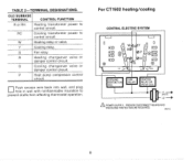
... wire back into wall. PROVIDE DISCONNECT MEANSAND OVERLOAD PROTECTION AS REOUIRED. and plug hole in wall with nonflammable insulation to control circuit. OLDSUBBASE TERMINAL CONTROL FUNCTION R or RH Heating transformer power to control circuit RC Cooling transformer power to prevent drafts from affecting thermostat operation. M%1* 8 For CT1502 heatinglcooling CENTRAL ELECTRIC SYSTEM I 1 II U CONTACTOR...
... wire back into wall. PROVIDE DISCONNECT MEANSAND OVERLOAD PROTECTION AS REOUIRED. and plug hole in wall with nonflammable insulation to control circuit. OLDSUBBASE TERMINAL CONTROL FUNCTION R or RH Heating transformer power to control circuit RC Cooling transformer power to prevent drafts from affecting thermostat operation. M%1* 8 For CT1502 heatinglcooling CENTRAL ELECTRIC SYSTEM I 1 II U CONTACTOR...

Owner's Manual
Page 11
... WIRETO"Y"AND0NE TO " W . IF OLD THERMOSTAT USES A W2 (AUXILIARY OR EMERGENCY HEAT) TERMINAL, THIS THERMOSTAT MAY NOT BE USED THIS THERMOSTAT IS NOT DESIGNED TO CONTROL AUXILIARY HEAT A SOMEHEATPUMPSUSE"B"INSTEAD0F"O' M211511 0Connect the wires to W terminal. IMPORTaNT- U S t ' Y AND " W ' O N NEW THERMOSTAT, DO NOT U S E.../ 1 0 CQZOOA OR 0313A THERMOPILE 69-0273-9 CT1502, continued SINGLE STAGE HEAT PUMP (WITHOUT AUXILIARY HEAT) SYSTEM I- -1 For CT1503 750-millivolt heating Connect either wire to R terminal and the other wire to matching terminals on the subbase.
... WIRETO"Y"AND0NE TO " W . IF OLD THERMOSTAT USES A W2 (AUXILIARY OR EMERGENCY HEAT) TERMINAL, THIS THERMOSTAT MAY NOT BE USED THIS THERMOSTAT IS NOT DESIGNED TO CONTROL AUXILIARY HEAT A SOMEHEATPUMPSUSE"B"INSTEAD0F"O' M211511 0Connect the wires to W terminal. IMPORTaNT- U S t ' Y AND " W ' O N NEW THERMOSTAT, DO NOT U S E.../ 1 0 CQZOOA OR 0313A THERMOPILE 69-0273-9 CT1502, continued SINGLE STAGE HEAT PUMP (WITHOUT AUXILIARY HEAT) SYSTEM I- -1 For CT1503 750-millivolt heating Connect either wire to R terminal and the other wire to matching terminals on the subbase.
Owner's Manual
Page 13
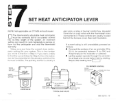
NOTE: Not applicable on CT1503 millivolt model. 0The thermostat's adjustable heat anticipator must be found printed on the primary control at least one minute before taklng reading. An incorrect setting can result in Step 3 If you were unable to find the current draw for... swings or burn out the anticipator and void the thermostat warranty. The primary control is usually a gas valve a relay or burner controi box, Aquastat controller or zone valve with the thermostat wires connected to it These controls are usually located behind the furnace cover See next illustration If current rating is...
NOTE: Not applicable on CT1503 millivolt model. 0The thermostat's adjustable heat anticipator must be found printed on the primary control at least one minute before taklng reading. An incorrect setting can result in Step 3 If you were unable to find the current draw for... swings or burn out the anticipator and void the thermostat warranty. The primary control is usually a gas valve a relay or burner controi box, Aquastat controller or zone valve with the thermostat wires connected to it These controls are usually located behind the furnace cover See next illustration If current rating is...
Owner's Manual
Page 14
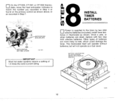
Other types of batteries are dead, replace with two new AAA alkaline batteries. The thermostat itself will operate without batteries, but will not operate as shown. On the CT1500. CT1501 or CT1502 thermostats, move the heat anticipator indicator to leak, which could damage the timer. Once a year, or when batteries are more likely to match the number you recorded in Step 4 or found on the primary control as shown above, or as recorded in Step 7 "8INSTALL F TIMER BATTERIES 0 \ANTICIPATOR SETTING LEVER 11,7164\ teries in thermostat as a fuel saver. 12
Other types of batteries are dead, replace with two new AAA alkaline batteries. The thermostat itself will operate without batteries, but will not operate as shown. On the CT1500. CT1501 or CT1502 thermostats, move the heat anticipator indicator to leak, which could damage the timer. Once a year, or when batteries are more likely to match the number you recorded in Step 4 or found on the primary control as shown above, or as recorded in Step 7 "8INSTALL F TIMER BATTERIES 0 \ANTICIPATOR SETTING LEVER 11,7164\ teries in thermostat as a fuel saver. 12
Owner's Manual
Page 17
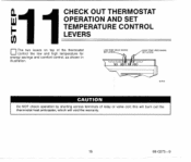
LOW TEMP.lBL"E MARK1 SET LEVER 1 Do NOT check operation by shorting across terminals of the thermostat control the low and high temperature for energy savings and comfort control, as shown in illustration. this will burn out the thermostat heat anticipator, which will void the warranty. cin l1CHECK OUT THERMOSTAT OPERATION AND SET b TEMPERATURE CONTROL LEVERS The two levers on top of relay or valve coil; I 15 69-0273-9 ~
LOW TEMP.lBL"E MARK1 SET LEVER 1 Do NOT check operation by shorting across terminals of the thermostat control the low and high temperature for energy savings and comfort control, as shown in illustration. this will burn out the thermostat heat anticipator, which will void the warranty. cin l1CHECK OUT THERMOSTAT OPERATION AND SET b TEMPERATURE CONTROL LEVERS The two levers on top of relay or valve coil; I 15 69-0273-9 ~
Owner's Manual
Page 18
... system switch at least one complete cycle with the system switch in any time delay that may be built into the compressor control circuit. 0 Movebothleverstogether5°F[30C]aboveroom temperature. The heat should not operate. 0 Operate the entire system for at OFF. Heating... guide in owner's manual. The cooling equipment should operate, and the fan will startwhen the furnace heats up . Move both temperature control levers together at AUTO. 0 Pushbothtemperaturecontrol leverstogetherat least 5'F [3"C] above room temperature. IMPORTANT If thermostat fails any test, refer to the ...
... system switch at least one complete cycle with the system switch in any time delay that may be built into the compressor control circuit. 0 Movebothleverstogether5°F[30C]aboveroom temperature. The heat should not operate. 0 Operate the entire system for at OFF. Heating... guide in owner's manual. The cooling equipment should operate, and the fan will startwhen the furnace heats up . Move both temperature control levers together at AUTO. 0 Pushbothtemperaturecontrol leverstogetherat least 5'F [3"C] above room temperature. IMPORTANT If thermostat fails any test, refer to the ...
Owner's Manual
Page 20
Residential and Building Controls Division Honeywell Inc. 1985 Douglas Drive No. Golden Valley, MN 55422 Residential and Building Controls Division Honeywell Limited-Honeywell 740 Ellesmere Road Scarborough, Ontario M1P 2VY Lunltke Honeywell Helping You Conlrol Your World
Residential and Building Controls Division Honeywell Inc. 1985 Douglas Drive No. Golden Valley, MN 55422 Residential and Building Controls Division Honeywell Limited-Honeywell 740 Ellesmere Road Scarborough, Ontario M1P 2VY Lunltke Honeywell Helping You Conlrol Your World


