Owners Guide
Page 1
Hydronic Zoning Thermostat AQ1000TN2 OWNER'S GUIDE Place Bar Code Here
Hydronic Zoning Thermostat AQ1000TN2 OWNER'S GUIDE Place Bar Code Here
Owners Guide
Page 3
Table of contents User's section About your new thermostat 1 Screen display ...2 Power-up / modes of operation 3 User's configuration menu 4 Temperature display and setting 6 Installer's section Installation...7 Configuration switches 8 Installer's configuration menu 9 Appendix Technical specifications 12 2-year limited warranty 13 69-2005EF
Table of contents User's section About your new thermostat 1 Screen display ...2 Power-up / modes of operation 3 User's configuration menu 4 Temperature display and setting 6 Installer's section Installation...7 Configuration switches 8 Installer's configuration menu 9 Appendix Technical specifications 12 2-year limited warranty 13 69-2005EF
Owners Guide
Page 4
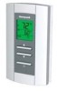
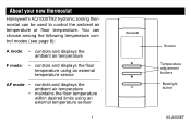
You can be used to control the ambient air temperature or floor temperature. About your new thermostat Honeywell's AQ1000TN2 hydronic zoning thermostat can choose among the following temperature control modes (see page 8): A mode: • controls and displays the ambient air temperature F mode: • controls and displays the ...
You can be used to control the ambient air temperature or floor temperature. About your new thermostat Honeywell's AQ1000TN2 hydronic zoning thermostat can choose among the following temperature control modes (see page 8): A mode: • controls and displays the ambient air temperature F mode: • controls and displays the ...
Owners Guide
Page 5
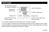
Screen display The arrow appears when the setpoint is displayed Temperature control mode Indoor temperature Outdoor temperature 1 Heating is On Keypad lock 2 Freeze Protection mode (see next page) Comfort / Unoccupied mode (see next page) 1 The outdoor temperature will be displayed only if the data is available. 2 This icon appears to indicate that the thermostat settings cannot be used to activate the backlight and to display the setpoint. 2 69-2005EF The backlight button and the buttons can still be modified as the hydronic zoning controller has locked the keypad.
Screen display The arrow appears when the setpoint is displayed Temperature control mode Indoor temperature Outdoor temperature 1 Heating is On Keypad lock 2 Freeze Protection mode (see next page) Comfort / Unoccupied mode (see next page) 1 The outdoor temperature will be displayed only if the data is available. 2 This icon appears to indicate that the thermostat settings cannot be used to activate the backlight and to display the setpoint. 2 69-2005EF The backlight button and the buttons can still be modified as the hydronic zoning controller has locked the keypad.
Owners Guide
Page 6
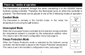
... activated by the temperature setback value. This value is set in the User's configuration menu (see page 10). 3 69-2005EF Therefore, the thermostat turns on when the controller is set in the Installer's configuration menu (see page 5). In this mode, the temperature is set using the ...buttons. This value is powered. The thermostat can be placed in one of the 3 following modes of operation The thermostat is normally in the Comfort mode. Power-up / modes of operation: Comfort Mode The thermostat is powered through the wires connecting it to the AQ2000 ...
... activated by the temperature setback value. This value is set in the User's configuration menu (see page 10). 3 69-2005EF Therefore, the thermostat turns on when the controller is set in the Installer's configuration menu (see page 5). In this mode, the temperature is set using the ...buttons. This value is powered. The thermostat can be placed in one of the 3 following modes of operation The thermostat is normally in the Comfort mode. Power-up / modes of operation: Comfort Mode The thermostat is powered through the wires connecting it to the AQ2000 ...
Owners Guide
Page 8
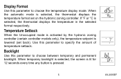
... Setback When the Unoccupied mode is activated by the hydronic zoning controller (certain controller models only), the temperature setpoint is selected, the thermostat displays the temperature format set back). When temporary backlight is selected, the screen is lit for 12 seconds every time any button is... selected, the thermostat displays the temperature in the selected format respectively. If °F or °C is pressed. 5 69-2005EF Display Format Use this ...
... Setback When the Unoccupied mode is activated by the hydronic zoning controller (certain controller models only), the temperature setpoint is selected, the thermostat displays the temperature format set back). When temporary backlight is selected, the screen is lit for 12 seconds every time any button is... selected, the thermostat displays the temperature in the selected format respectively. If °F or °C is pressed. 5 69-2005EF Display Format Use this ...
Owners Guide
Page 9
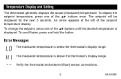
...setpoint will be displayed for the next 5 seconds. An arrow appears at the left of the buttons until the desired temperature is displayed. Verify the thermostat and external (floor) sensor connections. 6 69-2005EF To change the setpoint, press one of the buttons once. To display the setpoint temperature, ...press one of the setpoint temperature display. To scroll faster, press and hold the button. Temperature Display and Setting The thermostat generally displays the actual (measured) temperature. Error Messages The measured temperature is above the...
...setpoint will be displayed for the next 5 seconds. An arrow appears at the left of the buttons until the desired temperature is displayed. Verify the thermostat and external (floor) sensor connections. 6 69-2005EF To change the setpoint, press one of the buttons once. To display the setpoint temperature, ...press one of the setpoint temperature display. To scroll faster, press and hold the button. Temperature Display and Setting The thermostat generally displays the actual (measured) temperature. Error Messages The measured temperature is above the...
Owners Guide
Page 10
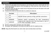
... Description 1 TH 2 TH 3 SENSOR 4 SENSOR AQ2000 Series hydronic zoning controller connections External sensor connections for floor temperature measurement (required only if the thermostat is set to observe). Insert the wires through the center hole of the faceplate up. Set the configuration switches (see pages 1 and 8) 4. Re... to the wall or onto an electrical box. 3. Installation 1. Remove the faceplate from the base by unscrewing the screw underneath the thermostat and tilting the bottom of the base and secure the base to the base and secure with the captive screw.
... Description 1 TH 2 TH 3 SENSOR 4 SENSOR AQ2000 Series hydronic zoning controller connections External sensor connections for floor temperature measurement (required only if the thermostat is set to observe). Insert the wires through the center hole of the faceplate up. Set the configuration switches (see pages 1 and 8) 4. Re... to the wall or onto an electrical box. 3. Installation 1. Remove the faceplate from the base by unscrewing the screw underneath the thermostat and tilting the bottom of the base and secure the base to the base and secure with the captive screw.
Owners Guide
Page 11
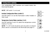
NOTE : F or AF mode should be used . Temperature Control Mode (switches 3 & 4) Use DIP switches 3 and 4 to set the thermostat in either Installer or User mode. Installer Configuration Menu (switch 2) Use DIP switch 2 to select the temperature control mode (A, F or AF). Configuration switches The configuration (DIP) switches are located behind the thermostat faceplate. NOTE : DIP switch 1 is not used only when an external (floor) sensor is connected to the thermostat (see page 7). 8 69-2005EF
NOTE : F or AF mode should be used . Temperature Control Mode (switches 3 & 4) Use DIP switches 3 and 4 to set the thermostat in either Installer or User mode. Installer Configuration Menu (switch 2) Use DIP switch 2 to select the temperature control mode (A, F or AF). Configuration switches The configuration (DIP) switches are located behind the thermostat faceplate. NOTE : DIP switch 1 is not used only when an external (floor) sensor is connected to the thermostat (see page 7). 8 69-2005EF
Owners Guide
Page 12
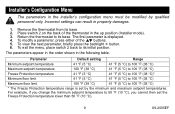
... °C) to 100 °F (38 °C) Maximum floor limit 100 °F (38 °C) 41 °F (5 °C) to its initial position. Return the thermostat to 100 °F (38 °C) * The Freeze Protection temperature range is displayed. 4. To exit the menu, place switch 2 back to 50 °F (10 °...Freeze Protection temperature lower than 50 °F (10 °C). 9 69-2005EF Incorrect settings can result in the following table. Remove the thermostat from its base. 2. Place switch 2 on the back of the buttons. 5. For example, if you cannot then set by qualified ...
... °C) to 100 °F (38 °C) Maximum floor limit 100 °F (38 °C) 41 °F (5 °C) to its initial position. Return the thermostat to 100 °F (38 °C) * The Freeze Protection temperature range is displayed. 4. To exit the menu, place switch 2 back to 50 °F (10 °...Freeze Protection temperature lower than 50 °F (10 °C). 9 69-2005EF Incorrect settings can result in the following table. Remove the thermostat from its base. 2. Place switch 2 on the back of the buttons. 5. For example, if you cannot then set by qualified ...
Owners Guide
Page 13
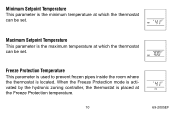
When the Freeze Protection mode is activated by the hydronic zoning controller, the thermostat is located. Minimum Setpoint Temperature This parameter is the minimum temperature at which the thermostat can be set . Maximum Setpoint Temperature This parameter is the maximum temperature at the Freeze Protection temperature. 10 69-2005EF Freeze Protection Temperature This parameter is used to prevent frozen pipes inside the room where the thermostat is placed at which the thermostat can be set .
When the Freeze Protection mode is activated by the hydronic zoning controller, the thermostat is located. Minimum Setpoint Temperature This parameter is the minimum temperature at which the thermostat can be set . Maximum Setpoint Temperature This parameter is the maximum temperature at the Freeze Protection temperature. 10 69-2005EF Freeze Protection Temperature This parameter is used to prevent frozen pipes inside the room where the thermostat is placed at which the thermostat can be set .
Owners Guide
Page 14
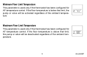
If the floor temperature is below that limit, the pump or valve will be deactivated regardless of the ambient temperature. Maximum Floor Limit Temperature This parameter is used only if the thermostat has been configured for AF temperature control. If the floor temperature is above that limit, the pump or valve will be activated regardless of the ambient temperature. 11 69-2005EF Minimum Floor Limit Temperature This parameter is used only if the thermostat has been configured for AF temperature control.
If the floor temperature is below that limit, the pump or valve will be deactivated regardless of the ambient temperature. Maximum Floor Limit Temperature This parameter is used only if the thermostat has been configured for AF temperature control. If the floor temperature is above that limit, the pump or valve will be activated regardless of the ambient temperature. 11 69-2005EF Minimum Floor Limit Temperature This parameter is used only if the thermostat has been configured for AF temperature control.


