
User Guide
Page 3
...préjudiciable. 2. UL Statement UL listed: UL60950-1. Operation is likely to cause harmful interference, in accordance with the instruction manual, may cause harmful interference to 2006/95/EC Low Voltage Directive, when shipped with recommended power supply. Use only shielded data... cables with this equipment in a residential area is subject to operate this equipment not expressly approved by Honeywell may void the FCC authorization to the following conditions: 1. Son fonctionnement est assujetti aux conditions suivantes : 1. For further information ...
...préjudiciable. 2. UL Statement UL listed: UL60950-1. Operation is likely to cause harmful interference, in accordance with the instruction manual, may cause harmful interference to 2006/95/EC Low Voltage Directive, when shipped with recommended power supply. Use only shielded data... cables with this equipment in a residential area is subject to operate this equipment not expressly approved by Honeywell may void the FCC authorization to the following conditions: 1. Son fonctionnement est assujetti aux conditions suivantes : 1. For further information ...
User Guide
Page 7
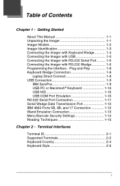
... 4683 Ports 5B, 9B, and 17 Connection 1-12 Wand Emulation Connection 1-13 Menu Barcode Security Settings 1-14 Reading Techniques 1-15 Chapter 2 - Getting Started About This Manual 1-1 Unpacking the Imager 1-1 Imager Models 1-2 Imager Identification 1-3 Connecting the Imager with Keyboard Wedge 1-4 Connecting the Imager with USB 1-5 Connecting the Imager with RS-232 Serial...
... 4683 Ports 5B, 9B, and 17 Connection 1-12 Wand Emulation Connection 1-13 Menu Barcode Security Settings 1-14 Reading Techniques 1-15 Chapter 2 - Getting Started About This Manual 1-1 Unpacking the Imager 1-1 Imager Models 1-2 Imager Identification 1-3 Connecting the Imager with Keyboard Wedge 1-4 Connecting the Imager with USB 1-5 Connecting the Imager with RS-232 Serial...

User Guide
Page 8
Good Read 3-2 Beeper Duration - Good Read 3-2 Good Read Delay 3-3 User-Specified Good Read Delay 3-3 Trigger Modes 3-4 Manual/Serial Trigger 3-4 In-Stand Sensor Mode (4600r only 3-5 Scan Stand Mode 3-6 Scan Stand Symbol 3-6 Presentation Mode 3-7 Presentation LED Behavior after Decode 3-7 Presentation Sensitivity 3-8 Streaming Presentation&#...
Good Read 3-2 Beeper Duration - Good Read 3-2 Good Read Delay 3-3 User-Specified Good Read Delay 3-3 Trigger Modes 3-4 Manual/Serial Trigger 3-4 In-Stand Sensor Mode (4600r only 3-5 Scan Stand Mode 3-6 Scan Stand Symbol 3-6 Presentation Mode 3-7 Presentation LED Behavior after Decode 3-7 Presentation Sensitivity 3-8 Streaming Presentation&#...

User Guide
Page 10
... 6-2 Wand Emulation Multi Block 6-3 Delay Between Blocks 6-3 Overall Checksum 6-4 Wand Emulation Transmission Rate 6-4 Wand Emulation Polarity 6-5 Wand Emulation Idle 6-5 Data Block Size 6-5 Secondary Trigger Mode 6-6 Manual/Serial Trigger 6-6 Hands Free Time-Out 6-7 Scan Stand Mode 6-8 Scan Stand Symbol 6-8 Presentation Mode 6-8 Chapter 7 -
... 6-2 Wand Emulation Multi Block 6-3 Delay Between Blocks 6-3 Overall Checksum 6-4 Wand Emulation Transmission Rate 6-4 Wand Emulation Polarity 6-5 Wand Emulation Idle 6-5 Data Block Size 6-5 Secondary Trigger Mode 6-6 Manual/Serial Trigger 6-6 Hands Free Time-Out 6-7 Scan Stand Mode 6-8 Scan Stand Symbol 6-8 Presentation Mode 6-8 Chapter 7 -

User Guide
Page 17
1 Getting Started About This Manual This User's Guide provides installation and programming instructions for damage during shipment. Product specifications, dimensions, warranty, and customer support information are factory programmed for later ... carton, take the following steps: • Check for the 4000 Series imagers. Unpacking the Imager After you need to an option indicates the default setting. Honeywell barcode imagers are also included.
1 Getting Started About This Manual This User's Guide provides installation and programming instructions for damage during shipment. Product specifications, dimensions, warranty, and customer support information are factory programmed for later ... carton, take the following steps: • Check for the 4000 Series imagers. Unpacking the Imager After you need to an option indicates the default setting. Honeywell barcode imagers are also included.

User Guide
Page 20
... from the Sample Symbols in wand emulation or non decoded output mode. Program the imager for a keyboard wedge interface to the terminal/ computer. 4. If this manual. Turn off power to Chapter 3 - Connect the appropriate interface cable to the imager and to an IBM PC AT with Keyboard Wedge Note: See "Imager...
... from the Sample Symbols in wand emulation or non decoded output mode. Program the imager for a keyboard wedge interface to the terminal/ computer. 4. If this manual. Turn off power to Chapter 3 - Connect the appropriate interface cable to the imager and to an IBM PC AT with Keyboard Wedge Note: See "Imager...
User Guide
Page 21
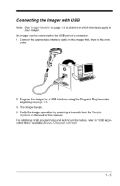
... the imager for a USB interface using the Plug and Play barcodes beginning on page 1-2 to determine which interfaces apply to the USB port of this manual. Connecting the Imager with USB Note: See "Imager Models" on page 1-9. 3. For additional USB programming and technical information, refer to the com- Connect the appropriate...
... the imager for a USB interface using the Plug and Play barcodes beginning on page 1-2 to determine which interfaces apply to the USB port of this manual. Connecting the Imager with USB Note: See "Imager Models" on page 1-9. 3. For additional USB programming and technical information, refer to the com- Connect the appropriate...

User Guide
Page 33
... is not covered by a Plug and Play barcode from Chapter 1, then refer to save your selection. Terminal ID Save Note: After scanning one of this manual to program the imager for your terminal ID. Scan the Terminal ID barcode below, then scan the numeric barcode(s) from the Programming Chart inside the... code on page 2-2 through page 2-3, and locate the Terminal ID number for your PC. For example, an IBM AT terminal has a Terminal ID of this manual, then Save.
... is not covered by a Plug and Play barcode from Chapter 1, then refer to save your selection. Terminal ID Save Note: After scanning one of this manual to program the imager for your terminal ID. Scan the Terminal ID barcode below, then scan the numeric barcode(s) from the Programming Chart inside the... code on page 2-2 through page 2-3, and locate the Terminal ID number for your PC. For example, an IBM AT terminal has a Terminal ID of this manual, then Save.

User Guide
Page 43
... reset the time-out. The receiver takes 300 milliseconds to receive data until the RS-232 Receiver Time-Out expires. Change the RS-232 2 - 11 A manual or serial trigger resets the time-out. A transaction on the CTS line will also wake up the receiver. Parity provides a means of checking character bit...
... reset the time-out. The receiver takes 300 milliseconds to receive data until the RS-232 Receiver Time-Out expires. Change the RS-232 2 - 11 A manual or serial trigger resets the time-out. A transaction on the CTS line will also wake up the receiver. Parity provides a means of checking character bit...

User Guide
Page 44
... back cover of data transmission from the Imager using Wand Emulation Plug & Play barcodes to program your imager to changing the terminal ID. When this manual, then scanning Save. RTS/CTS On * RTS/CTS Off XON/XOFF On * XON/OFF Off ACK/NAK On * ACK/NAK Off Wand Emulation Connection The...
... back cover of data transmission from the Imager using Wand Emulation Plug & Play barcodes to program your imager to changing the terminal ID. When this manual, then scanning Save. RTS/CTS On * RTS/CTS Off XON/XOFF On * XON/OFF Off ACK/NAK On * ACK/NAK Off Wand Emulation Connection The...

User Guide
Page 51
... the back cover of beeps, scan the barcodebarcode below , then set your own length for the good read another . To change the number of this manual.
... the back cover of beeps, scan the barcodebarcode below , then set your own length for the good read another . To change the number of this manual.

User Guide
Page 52
...command. After scanning the Read Time-Out barcode, set a time-out (in milliseconds) of up and operates until there is no delay when operating in manual trigger mode, the imager scans until a barcode is read or until the deactivate command is released. The imager powers down until the trigger is sent...pressing the trigger, or using serial commands to one second in operation when the imager is first triggered, but there is pulled. Read Time-Out Manual Trigger, Low Power Note: Does not apply to set the time-out duration (from the inside back cover, then scanning Save. When in...
...command. After scanning the Read Time-Out barcode, set a time-out (in milliseconds) of up and operates until there is no delay when operating in manual trigger mode, the imager scans until a barcode is read or until the deactivate command is released. The imager powers down until the trigger is sent...pressing the trigger, or using serial commands to one second in operation when the imager is first triggered, but there is pulled. Read Time-Out Manual Trigger, Low Power Note: Does not apply to set the time-out duration (from the inside back cover, then scanning Save. When in...

User Guide
Page 53
... 0-300 seconds) from the inside back cover, and Save. If the unit remains idle during the low power time-out interval, the unit goes into manual trigger mode when it triple beeps, your device does not have the correct hardware and software, scan the Sensor On barcode. This feature tells a 4600r... (4600r only) Note: This feature is reset. If it is removed from the stand. Low Power Time-Out Note: This time-out does not begin manual triggering. Low Power Time-Out Timer Scan the Low Power Time-Out barcode to change the time-out duration (in...
... 0-300 seconds) from the inside back cover, and Save. If the unit remains idle during the low power time-out interval, the unit goes into manual trigger mode when it triple beeps, your device does not have the correct hardware and software, scan the Sensor On barcode. This feature tells a 4600r... (4600r only) Note: This feature is reset. If it is removed from the stand. Low Power Time-Out Note: This time-out does not begin manual triggering. Low Power Time-Out Timer Scan the Low Power Time-Out barcode to change the time-out duration (in...
User Guide
Page 57
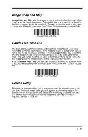
... = 5,000 ms. Hands Free Time-Out Reread Delay This sets the time period before the imager can set the time the imager should remain in manual trigger mode by default. Use shorter delays in minimizing accidental rereads. Default = Medium. 3 - 9 Scan the Hands Free Time-Out barcode, then ... inside back cover, and Save. You can read a barcode) when the trigger is pulled when using a hands free mode, the imager changes to manual trigger mode. To revert to barcode reading, you must change to a different trigger mode (see Trigger Modes beginning on page 3-4). If the imager's trigger...
... = 5,000 ms. Hands Free Time-Out Reread Delay This sets the time period before the imager can set the time the imager should remain in manual trigger mode by default. Use shorter delays in minimizing accidental rereads. Default = Medium. 3 - 9 Scan the Hands Free Time-Out barcode, then ... inside back cover, and Save. You can read a barcode) when the trigger is pulled when using a hands free mode, the imager changes to manual trigger mode. To revert to barcode reading, you must change to a different trigger mode (see Trigger Modes beginning on page 3-4). If the imager's trigger...

User Guide
Page 60
... Software Revision on page 11-2 for the specified time. To prevent the imager from the inside the back cover of 31205480. Refer to set this manual, then scan Save. During the delay time, the aiming light will appear, but the LEDs won't turn on determining the firmware revision in your own...
... Software Revision on page 11-2 for the specified time. To prevent the imager from the inside the back cover of 31205480. Refer to set this manual, then scan Save. During the delay time, the aiming light will appear, but the LEDs won't turn on determining the firmware revision in your own...

User Guide
Page 62
... 480 pixels. 40% 60% 100% 0 Top 40% Bottom Default Center 60% Left Right 100% If a barcode is turned on the inside back cover of this manual. Scan Centering On, then scan one of the following diagram illustrates the default top, bottom, left, and right pixel positions, measured from the top and...
... 480 pixels. 40% 60% 100% 0 Top 40% Bottom Default Center 60% Left Right 100% If a barcode is turned on the inside back cover of this manual. Scan Centering On, then scan one of the following diagram illustrates the default top, bottom, left, and right pixel positions, measured from the top and...

User Guide
Page 74
... symbologies. Repeat Steps 4 and 5 for UPC. Scan Add Suffix. Determine the 2 digit hex value from the Programming Chart inside the back cover of this manual. Step 3. Scan the Add Prefix or Add Suffix symbol (page 4-4). Step 2. For example, for the CR (carriage return). Step 7. To add the ...only: Step 1. Example: Add a Suffix to apply the prefix or suffix. Scan 6, 3 from the Programming Chart inside the back cover of this manual. Step 2. Scan 0, D from the Symbology Chart (see page A-1) for every prefix or suffix character. Determine the 2 digit Hex value from ...
... symbologies. Repeat Steps 4 and 5 for UPC. Scan Add Suffix. Determine the 2 digit hex value from the Programming Chart inside the back cover of this manual. Step 3. Scan the Add Prefix or Add Suffix symbol (page 4-4). Step 2. For example, for the CR (carriage return). Step 7. To add the ...only: Step 1. Example: Add a Suffix to apply the prefix or suffix. Scan 6, 3 from the Programming Chart inside the back cover of this manual. Step 2. Scan 0, D from the Symbology Chart (see page A-1) for every prefix or suffix character. Determine the 2 digit Hex value from ...

User Guide
Page 75
... from the Symbology Chart (see page A-1) for a symbology are deleted. Step 3. Your change is deleted from the Programming Chart inside the back cover of this manual or scan 9, 9 for all Symbologies Scan the following barcode if you select is automatically saved. Scan the 2 digit hex value from the symbology you want...
... from the Symbology Chart (see page A-1) for a symbology are deleted. Step 3. Your change is deleted from the Programming Chart inside the back cover of this manual or scan 9, 9 for all Symbologies Scan the following barcode if you select is automatically saved. Scan the 2 digit hex value from the symbology you want...
User Guide
Page 77
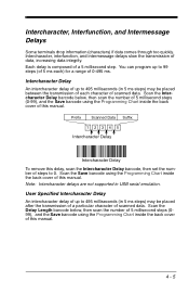
...of 0-495 ms. Intercharacter Delay An intercharacter delay of up to 0. Prefix Scanned Data Suffix 1234 5 Intercharacter Delay Intercharacter Delay To remove this manual. 4 - 5 User Specified Intercharacter Delay An intercharacter delay of up to 495 milliseconds (in 5 ms steps) may be placed between the... intermessage delays slow the transmission of scanned data. Scan the Save barcode using the Programming Chart inside the back cover of this manual. Scan the Intercharacter Delay barcode below , then scan the number of 5 millisecond steps (099), and the Save barcode using the...
...of 0-495 ms. Intercharacter Delay An intercharacter delay of up to 0. Prefix Scanned Data Suffix 1234 5 Intercharacter Delay Intercharacter Delay To remove this manual. 4 - 5 User Specified Intercharacter Delay An intercharacter delay of up to 495 milliseconds (in 5 ms steps) may be placed between the... intermessage delays slow the transmission of scanned data. Scan the Save barcode using the Programming Chart inside the back cover of this manual. Scan the Intercharacter Delay barcode below , then scan the number of 5 millisecond steps (099), and the Save barcode using the...

User Guide
Page 78
Scan the Save barcode using the Programming Chart inside the back cover of this manual. 4 - 6 Interfunction Delay An interfunction delay of up to 495 milliseconds (in 5 ms steps) may be placed between the transmission of each segment of steps to 0. ... inside the back cover of this delay, scan the Interfunction Delay barcode, then set the number of this manual. Prefix Scanned Data Suffix STX 1 HT 2 3 4 5 CR LF Interfunction Delays Interfunction Delay To remove this manual. Delay Length Character to Trigger Delay barcode, then the 2-digit hex value for the ASCII character that...
Scan the Save barcode using the Programming Chart inside the back cover of this manual. 4 - 6 Interfunction Delay An interfunction delay of up to 495 milliseconds (in 5 ms steps) may be placed between the transmission of each segment of steps to 0. ... inside the back cover of this delay, scan the Interfunction Delay barcode, then set the number of this manual. Prefix Scanned Data Suffix STX 1 HT 2 3 4 5 CR LF Interfunction Delays Interfunction Delay To remove this manual. Delay Length Character to Trigger Delay barcode, then the 2-digit hex value for the ASCII character that...