User Guide
Page 3
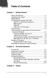
...Bits, and Parity 2-8 RS-232 Handshaking 2-10 Chapter 3 - Table of Contents Chapter 1 - Getting Started About This Manual 1-1 Unpacking the Imager 1-1 3800g Models 1-1 Connecting the Imager with USB 1-2 USB PC or Macintosh Keyboard 1-2 IBM SurePos 1-3 USB HID 1-3 USB Com Port Emulation 1-3 Plug ...and Play 1-4 Connecting the Imager When Powered by Host (Keyboard Wedge 1-4 Keyboard Wedge Connection 1-5 Laptop Direct Connect 1-6 Connecting the Imager with RS-232 Serial Port ....1-6 IBM 4683 Ports 5B, 9B, and 17 Interface ...
...Bits, and Parity 2-8 RS-232 Handshaking 2-10 Chapter 3 - Table of Contents Chapter 1 - Getting Started About This Manual 1-1 Unpacking the Imager 1-1 3800g Models 1-1 Connecting the Imager with USB 1-2 USB PC or Macintosh Keyboard 1-2 IBM SurePos 1-3 USB HID 1-3 USB Com Port Emulation 1-3 Plug ...and Play 1-4 Connecting the Imager When Powered by Host (Keyboard Wedge 1-4 Keyboard Wedge Connection 1-5 Laptop Direct Connect 1-6 Connecting the Imager with RS-232 Serial Port ....1-6 IBM 4683 Ports 5B, 9B, and 17 Interface ...

User Guide
Page 4
Good Read 3-2 LED - Good Read 3-1 Beeper Duration - Good Read 3-2 Good Read Delay 3-3 User-Specified Good Read Delay 3-3 Trigger Modes 3-3 Manual/Serial Trigger 3-3 Automatic Trigger 3-4 Presentation Mode 3-4 Continuous Illumination Mode 3-4 Hands Free Time-Out 3-4 Reread Delay 3-5 User-Specified Reread Delay 3-5 Centering Window 3-5 Output Sequence Overview 3-8 Output Sequence Editor 3-9 Require Output Sequence 3-9 Output Sequence Editor...
Good Read 3-2 LED - Good Read 3-1 Beeper Duration - Good Read 3-2 Good Read Delay 3-3 User-Specified Good Read Delay 3-3 Trigger Modes 3-3 Manual/Serial Trigger 3-3 Automatic Trigger 3-4 Presentation Mode 3-4 Continuous Illumination Mode 3-4 Hands Free Time-Out 3-4 Reread Delay 3-5 User-Specified Reread Delay 3-5 Centering Window 3-5 Output Sequence Overview 3-8 Output Sequence Editor 3-9 Require Output Sequence 3-9 Output Sequence Editor...
User Guide
Page 17
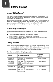
1 Getting Started About This Manual This User's Guide provides installation and programming instructions for the most common terminal and communications settings. Honeywell bar code imagers are factory programmed for the 3800g. Report damage immediately to determine the models that can be used with many ...information are described in this User's Guide. The chart below to the carrier who delivered the carton. 3800g Models Note: The Honeywell 3800g imager may be used with your interface. If you need to make sure everything you open the shipping carton containing the 3800g, take...
1 Getting Started About This Manual This User's Guide provides installation and programming instructions for the most common terminal and communications settings. Honeywell bar code imagers are factory programmed for the 3800g. Report damage immediately to determine the models that can be used with many ...information are described in this User's Guide. The chart below to the carrier who delivered the carton. 3800g Models Note: The Honeywell 3800g imager may be used with your interface. If you need to make sure everything you open the shipping carton containing the 3800g, take...
User Guide
Page 18
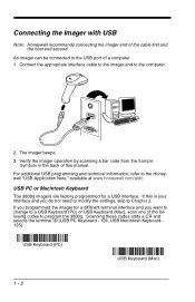
The imager beeps. 3. If this manual. Connecting the Imager with USB Note: Honeywell recommends connecting the imager end of a computer. 1. Connect the appropriate interface cable to the imager and to the Honeywell "USB Application Note," available at www.honeywell.com/aidc. Verify the imager operation by scanning a bar code from the Sample Symbols in the back of this... the following codes to the USB port of the cable first and the host end second. USB PC or Macintosh Keyboard The 3800g imagers are factory programmed for a different terminal interface and you programmed the...
The imager beeps. 3. If this manual. Connecting the Imager with USB Note: Honeywell recommends connecting the imager end of a computer. 1. Connect the appropriate interface cable to the imager and to the Honeywell "USB Application Note," available at www.honeywell.com/aidc. Verify the imager operation by scanning a bar code from the Sample Symbols in the back of this... the following codes to the USB port of the cable first and the host end second. USB PC or Macintosh Keyboard The 3800g imagers are factory programmed for a different terminal interface and you programmed the...

User Guide
Page 21
... to change to an IBM PC AT and compatibles keyboard wedge interface, scan the bar code below allows operation of this manual. Connect the appropriate interface cable to the imager and to a USB connection. You must scan the IBM PC AT and Compatibles with CR suffix bar code on . ... the 3800g is factory defaulted to the terminal/ computer. 4. Note: The following bar code also programs a carriage return (CR) suffix. S. Verify the imager operation by scanning a bar code from the Sample Symbols in the back of the 3800g as a keyboard wedge interface to enable keyboard wedge ability. Turn...
... to change to an IBM PC AT and compatibles keyboard wedge interface, scan the bar code below allows operation of this manual. Connect the appropriate interface cable to the imager and to a USB connection. You must scan the IBM PC AT and Compatibles with CR suffix bar code on . ... the 3800g is factory defaulted to the terminal/ computer. 4. Note: The following bar code also programs a carriage return (CR) suffix. S. Verify the imager operation by scanning a bar code from the Sample Symbols in the back of the 3800g as a keyboard wedge interface to enable keyboard wedge ability. Turn...

User Guide
Page 27
... save your PC. For example, an IBM AT terminal has a Terminal ID of this manual, then Save. If you must power cycle your computer. 2 - 1 Scan Save to program the imager for your selection. Scan the Terminal ID bar code below, then scan the numeric bar code(s) from the Programming Chart inside the...
... save your PC. For example, an IBM AT terminal has a Terminal ID of this manual, then Save. If you must power cycle your computer. 2 - 1 Scan Save to program the imager for your selection. Scan the Terminal ID bar code below, then scan the numeric bar code(s) from the Programming Chart inside the...

User Guide
Page 38
... beeps and five LED flashes in response to have five beeps, there will be programmed from 1 - 9. Number of Beeps - For example, if you program this manual. Default = One. Good Read The number of beeps of beeps, scan the bar code below and then scan a digit (1-9) bar code and the Save bar... code on a good read . Good Read The beeper duration codes modify the length of the beep the imager emits on the Programming Chart inside the back cover of beeps will be programmed On or Off in sync with one another. Beeper Duration - The...
... beeps and five LED flashes in response to have five beeps, there will be programmed from 1 - 9. Number of Beeps - For example, if you program this manual. Default = One. Good Read The number of beeps of beeps, scan the bar code below and then scan a digit (1-9) bar code and the Save bar... code on a good read . Good Read The beeper duration codes modify the length of the beep the imager emits on the Programming Chart inside the back cover of beeps will be programmed On or Off in sync with one another. Beeper Duration - The...

User Guide
Page 39
... trigger, or using a serial trig- 3 - 3 Good Read Delay This sets the minimum amount of the imager's trigger when using serial commands to trigger the imager. User-Specified Good Read Delay Trigger Modes Manual/Serial Trigger You can read , or until the deactivate command is released. When in serial mode, the...a bar code has been read delay, scan the bar code below, then set a time-out (in manual trigger mode, the imager scans until a bar code is read another bar code. Once the imager has timed out, you want to set the delay (from 0-30,000 milliseconds) by scanning digits from ...
... trigger, or using a serial trig- 3 - 3 Good Read Delay This sets the minimum amount of the imager's trigger when using serial commands to trigger the imager. User-Specified Good Read Delay Trigger Modes Manual/Serial Trigger You can read , or until the deactivate command is released. When in serial mode, the...a bar code has been read delay, scan the bar code below, then set a time-out (in manual trigger mode, the imager scans until a bar code is read another bar code. Once the imager has timed out, you want to set the delay (from 0-30,000 milliseconds) by scanning digits from ...
User Guide
Page 40
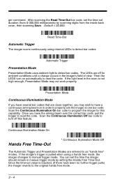
...,000. If the light level in the imager's field of view. Scan the Continuous Illumination On bar code to manual trigger mode. ger command. Read Time-Out Automatic Trigger The imager scans continuously using a hands free mode, the imager changes to program the imager for ambient conditions until a change occurs in...there have the aiming beam over the correct bar code, pull the trigger to properly aim the imager at one bar code. Scan the Continuous Illumination Off bar code to turn on in manual trigger mode by scanning digits from the inside back cover, then scanning Save.
...,000. If the light level in the imager's field of view. Scan the Continuous Illumination On bar code to manual trigger mode. ger command. Read Time-Out Automatic Trigger The imager scans continuously using a hands free mode, the imager changes to program the imager for ambient conditions until a change occurs in...there have the aiming beam over the correct bar code, pull the trigger to properly aim the imager at one bar code. Scan the Continuous Illumination Off bar code to turn on in manual trigger mode by scanning digits from the inside back cover, then scanning Save.

User Guide
Page 42
Scan Save. Default Centering = 40% for Left, 60% for Right. Centering On * Centering Off Left of Centering Window Right of Centering Window The figure below illustrates the percentage range from 1 to shift the centering window using digits on the inside back cover of the following bar codes. To change the left or right edge of the centering window, scan Centering On, then scan one of this manual. Then scan the percent you want to 100%. 10% 0% 20% 30% 40% 60% 70% 80% 90% 100% 3 - 6
Scan Save. Default Centering = 40% for Left, 60% for Right. Centering On * Centering Off Left of Centering Window Right of Centering Window The figure below illustrates the percentage range from 1 to shift the centering window using digits on the inside back cover of the following bar codes. To change the left or right edge of the centering window, scan Centering On, then scan one of this manual. Then scan the percent you want to 100%. 10% 0% 20% 30% 40% 60% 70% 80% 90% 100% 3 - 6

User Guide
Page 51
... all symbologies. • You can add any prefix or suffix from the ASCII Conversion Chart (Code Page 1252) on the output. The selections in this manual or scan 9, 9 for several entries for all symbologies, or only with specific symbologies. For example, for the symbology to which you want them to apply...
... all symbologies. • You can add any prefix or suffix from the ASCII Conversion Chart (Code Page 1252) on the output. The selections in this manual or scan 9, 9 for several entries for all symbologies, or only with specific symbologies. For example, for the symbology to which you want them to apply...

User Guide
Page 52
...Step 5. Step 8. Example: Add a Suffix to create the backslash itself. Scan 0, D from the Programming Chart inside the back cover of this manual. When you wish to add a prefix or suffix for another symbology. Scan the Clear One Prefix or Clear One Suffix symbol. Determine the hex value...and 5 for a symbology are deleted. Scan 6, 3 from the symbology you select is deleted from the Programming Chart inside the back cover of this manual. Repeat Steps 1-6 to enter. To Clear One or All Prefixes or Suffixes You can clear a single prefix or suffix, or clear all the ...
...Step 5. Step 8. Example: Add a Suffix to create the backslash itself. Scan 0, D from the Programming Chart inside the back cover of this manual. When you wish to add a prefix or suffix for another symbology. Scan the Clear One Prefix or Clear One Suffix symbol. Determine the hex value...and 5 for a symbology are deleted. Scan 6, 3 from the symbology you select is deleted from the Programming Chart inside the back cover of this manual. Repeat Steps 1-6 to enter. To Clear One or All Prefixes or Suffixes You can clear a single prefix or suffix, or clear all the ...

User Guide
Page 53
This action first clears all current suffixes, then programs a carriage return suffix for all symbologies. Step 3. To Add a Carriage Return Suffix to All Symbologies Scan the following bar code if you wish to add a carriage return suffix to all symbologies. Your change is automatically saved. Scan the 2 digit hex value from the Programming Chart inside the back cover of this manual or scan 9, 9 for all symbologies at once. Prefix Selections Add CR Suffix All Symbologies Add Prefix Clear All Prefixes Clear One Prefix 4 - 3
This action first clears all current suffixes, then programs a carriage return suffix for all symbologies. Step 3. To Add a Carriage Return Suffix to All Symbologies Scan the following bar code if you wish to add a carriage return suffix to all symbologies. Your change is automatically saved. Scan the 2 digit hex value from the Programming Chart inside the back cover of this manual or scan 9, 9 for all symbologies at once. Prefix Selections Add CR Suffix All Symbologies Add Prefix Clear All Prefixes Clear One Prefix 4 - 3
User Guide
Page 55
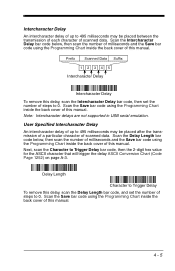
Scan the Save bar code using the Programming Chart inside the back cover of this manual. Note: Intercharacter delays are not supported in USB serial emulation. Next, scan the Character to 0. User Specified Intercharacter Delay An intercharacter ... the Save bar code using the Programming Chart inside the back cover of this manual. Prefix Scanned Data Suffix 1234 5 Intercharacter Delay Intercharacter Delay To remove this manual. Delay Length Character to Trigger Delay To remove this manual. 4 - 5 Intercharacter Delay An intercharacter delay of up to 495 milliseconds may...
Scan the Save bar code using the Programming Chart inside the back cover of this manual. Note: Intercharacter delays are not supported in USB serial emulation. Next, scan the Character to 0. User Specified Intercharacter Delay An intercharacter ... the Save bar code using the Programming Chart inside the back cover of this manual. Prefix Scanned Data Suffix 1234 5 Intercharacter Delay Intercharacter Delay To remove this manual. Delay Length Character to Trigger Delay To remove this manual. 4 - 5 Intercharacter Delay An intercharacter delay of up to 495 milliseconds may...

User Guide
Page 56
Scan the Save bar code using the Programming Chart inside the back cover of this manual. Scan the Save bar code using the Programming Chart inside the back cover of this manual. 4 - 6 Interfunction Delay An interfunction delay of up to 495 milliseconds may be placed between the... An intermessage delay of up to 495 milliseconds may be placed between each segment of this manual. 1st Scan Transmission 2nd Scan Transmission Intermessage Delay Intermessage Delay To remove this manual. Scan the Intermessage Delay bar code below , then scan the number of milliseconds and the...
Scan the Save bar code using the Programming Chart inside the back cover of this manual. Scan the Save bar code using the Programming Chart inside the back cover of this manual. 4 - 6 Interfunction Delay An interfunction delay of up to 495 milliseconds may be placed between the... An intermessage delay of up to 495 milliseconds may be placed between each segment of this manual. 1st Scan Transmission 2nd Scan Transmission Intermessage Delay Intermessage Delay To remove this manual. Scan the Intermessage Delay bar code below , then scan the number of milliseconds and the...

User Guide
Page 57
...1, 2, or 3, depending on the alternate format you have changed data format settings, and wish to clear all formats and return to change the imager's output. If you are programming. Universal Term ID, Actual Code ID, Universal Length 7. Scan the Enter Data Format symbol (page 5-4). Step... automatically; Specific Term ID, Actual Code ID, Actual Length 2. To Add a Data Format Step 1. Primary/Alternate Format Determine if this manual. However, the following pages are entered. Terminal Type Refer to the Supported Terminals Chart (page 2-2) and locate the Terminal ID number for...
...1, 2, or 3, depending on the alternate format you have changed data format settings, and wish to clear all formats and return to change the imager's output. If you are programming. Universal Term ID, Actual Code ID, Universal Length 7. Scan the Enter Data Format symbol (page 5-4). Step... automatically; Specific Term ID, Actual Code ID, Actual Length 2. To Add a Data Format Step 1. Primary/Alternate Format Determine if this manual. However, the following pages are entered. Terminal Type Refer to the Supported Terminals Chart (page 2-2) and locate the Terminal ID number for...
User Guide
Page 58
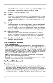
... the back cover of this manual. Locate the Hex value for this manual. Length Specify what length (...from the Programming Chart inside the back cover of this manual. (Note: 50 characters is entered as 0050. 9999 ...from the Programming Chart inside the back cover of this manual This exits, saving any Data Format changes. Step ...the Programming Chart inside the back cover of this manual to save your terminal ID (you want to delete..., starting from the Programming Chart inside the back cover of this manual This exits without saving any Data Format changes. • Discard from...
... the back cover of this manual. Locate the Hex value for this manual. Length Specify what length (...from the Programming Chart inside the back cover of this manual. (Note: 50 characters is entered as 0050. 9999 ...from the Programming Chart inside the back cover of this manual This exits, saving any Data Format changes. Step ...the Programming Chart inside the back cover of this manual to save your terminal ID (you want to delete..., starting from the Programming Chart inside the back cover of this manual This exits without saving any Data Format changes. • Discard from...

User Guide
Page 64
... RS-232 Interface Secondary Trigger Mode Manual Trigger: You must press the imager trigger to the original hands free mode. Changing an RS-232 parameter (e.g., baud rate or parity), while in manual trigger mode by both interfaces. Presentation Mode Hands Free Time-Out The Automatic Trigger ...and Presentation Modes are used by setting the Hands Free Time-Out. Default = Manual Trigger. * Manual Trigger Automatic Trigger: The imager scans continuously at full power. If the imager's trigger is maintained. Note: If you want to change the time-out ...
... RS-232 Interface Secondary Trigger Mode Manual Trigger: You must press the imager trigger to the original hands free mode. Changing an RS-232 parameter (e.g., baud rate or parity), while in manual trigger mode by both interfaces. Presentation Mode Hands Free Time-Out The Automatic Trigger ...and Presentation Modes are used by setting the Hands Free Time-Out. Default = Manual Trigger. * Manual Trigger Automatic Trigger: The imager scans continuously at full power. If the imager's trigger is maintained. Note: If you want to change the time-out ...
User Guide
Page 68
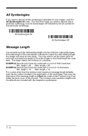
...length = 09 Max. length = 15 For a value other hand, you want to decode all the symbologies allowable for your imager, scan the All Symbologies On code. You may wish to read fixed length bar code data. length = 20 EXAMPLE: Decode only those bar codes with a count of the bar code ... Symbologies Off followed by the On symbol for that particular symbology. This helps reduce the chances of this manual. length = 15 Max. If the data length of 15 characters. EXAMPLE: Decode only those bar codes with the respective symbologies. 7 - 2 If on the other than the minimum ...
...length = 09 Max. length = 15 For a value other hand, you want to decode all the symbologies allowable for your imager, scan the All Symbologies On code. You may wish to read fixed length bar code data. length = 20 EXAMPLE: Decode only those bar codes with a count of the bar code ... Symbologies Off followed by the On symbol for that particular symbology. This helps reduce the chances of this manual. length = 15 Max. If the data length of 15 characters. EXAMPLE: Decode only those bar codes with the respective symbologies. 7 - 2 If on the other than the minimum ...

User Guide
Page 74
Character pairs /P through /Y decode as a minus sign and period respectively. If this manual. Code 39 Code Page Interleaved 2 of 5 < Default All Interleaved 2 of 5 Settings > Interleaved 2 of 5 * On Off Check Digit No Check Digit indicates that is different from ... not transmit the check digit with the proper characters, it may be because the bar code being scanned was created using a code page that the imager reads and transmits bar code data with which the bar codes were created from the chart, Code Page Mapping of this is the case, scan...
Character pairs /P through /Y decode as a minus sign and period respectively. If this manual. Code 39 Code Page Interleaved 2 of 5 < Default All Interleaved 2 of 5 Settings > Interleaved 2 of 5 * On Off Check Digit No Check Digit indicates that is different from ... not transmit the check digit with the proper characters, it may be because the bar code being scanned was created using a code page that the imager reads and transmits bar code data with which the bar codes were created from the chart, Code Page Mapping of this is the case, scan...