

User Guide
Page 4
.../95/EC Low Voltage Directive, when shipped with recommended power supply. Europe The CE marking on waste electrical and electronic equipment (WEEE). This equipment is intended for product disposal. product safety. Nijverheidsweg 9-13 5627 BT Eindhoven The Netherlands Honeywell shall not be disposed of along with municipal waste and... for its production. c-UL Statement C-UL listed: CSA C22.2 No.60950-1-03, 2nd Edition for use of our product with equipment (i.e., power supplies, personal computers, etc.) that is not CE marked and does not comply with the Low Voltage Directive.
.../95/EC Low Voltage Directive, when shipped with recommended power supply. Europe The CE marking on waste electrical and electronic equipment (WEEE). This equipment is intended for product disposal. product safety. Nijverheidsweg 9-13 5627 BT Eindhoven The Netherlands Honeywell shall not be disposed of along with municipal waste and... for its production. c-UL Statement C-UL listed: CSA C22.2 No.60950-1-03, 2nd Edition for use of our product with equipment (i.e., power supplies, personal computers, etc.) that is not CE marked and does not comply with the Low Voltage Directive.

User Guide
Page 22
... Held Products battery may result in the base that is connected to the cordless image scanner by the warranty. Refer to "2020 LED Sequences and Their Meaning" on page 11-1.) Charging Information The battery is designed to charge while the image scanner is ... in the image scanner handle. Cordless System: Main Components Battery Contained in the cordless base unit. Each image scanner is supplied to an appropriate power supply. 1 - 2 Use ! Power is shipped with a battery. (See Product Specifications beginning on page 1-15 for an interpretation of Hand Held Products Li-...
... Held Products battery may result in the base that is connected to the cordless image scanner by the warranty. Refer to "2020 LED Sequences and Their Meaning" on page 11-1.) Charging Information The battery is designed to charge while the image scanner is ... in the image scanner handle. Cordless System: Main Components Battery Contained in the cordless base unit. Each image scanner is supplied to an appropriate power supply. 1 - 2 Use ! Power is shipped with a battery. (See Product Specifications beginning on page 1-15 for an interpretation of Hand Held Products Li-...

User Guide
Page 24
Base Charge Mode In order for the battery to be charged, there must be supplied to the base: Condition 1:9VDC power supply connected to work. There are three conditions during which power can be enough voltage for your application. Automatic Full Charge Rate Condition 1 Fast Charge Fast Charge ...Battery Charge Off Slow Charge No Charge Slow Charge No Charge No Charge No Charge Using a slow charge rate draws less current (power) from the input power source when the battery is mostly discharged. Default = Automatic. * Automatic Low Charge Rate Full Charge Rate Battery Charge Off 1...
Base Charge Mode In order for the battery to be charged, there must be supplied to the base: Condition 1:9VDC power supply connected to work. There are three conditions during which power can be enough voltage for your application. Automatic Full Charge Rate Condition 1 Fast Charge Fast Charge ...Battery Charge Off Slow Charge No Charge Slow Charge No Charge No Charge No Charge Using a slow charge rate draws less current (power) from the input power source when the battery is mostly discharged. Default = Automatic. * Automatic Low Charge Rate Full Charge Rate Battery Charge Off 1...

User Guide
Page 39
... to operate the interface. Connect the appropriate interface cable to the base and to be charged, and no power is not charged when in the bottom of the terminal/computer. 3. Program the base for the keyboard wedge... in the back of this mode. Turn the terminal/computer power back on page 1-21.) 6. Note: Without using the 9-volt external, power supply, the base only uses enough power from the back of the base and that the base sits...bar code from the host. 1 - 19 Using the 9-volt, external power supply allows the image scanner's battery to the terminal/ computer and keyboard. 2.
... to operate the interface. Connect the appropriate interface cable to the base and to be charged, and no power is not charged when in the bottom of the terminal/computer. 3. Program the base for the keyboard wedge... in the back of this mode. Turn the terminal/computer power back on page 1-21.) 6. Note: Without using the 9-volt external, power supply, the base only uses enough power from the back of the base and that the base sits...bar code from the host. 1 - 19 Using the 9-volt, external power supply allows the image scanner's battery to the terminal/ computer and keyboard. 2.
User Guide
Page 44
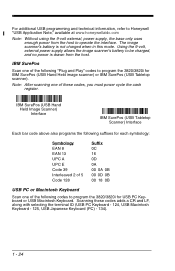
...Scanning these codes, you must power cycle the cash register. Using the 9-volt, external power supply allows the image scanner's battery to be charged, and no power is not charged when in this mode. For additional USB programming and technical information, refer to Honeywell "USB Application Note," available... at www.honeywellaidc.com Note: Without using the 9-volt external, power supply, the base only uses enough power from the host. Note: After scanning one of the following...
...Scanning these codes, you must power cycle the cash register. Using the 9-volt, external power supply allows the image scanner's battery to be charged, and no power is not charged when in this mode. For additional USB programming and technical information, refer to Honeywell "USB Application Note," available... at www.honeywellaidc.com Note: Without using the 9-volt external, power supply, the base only uses enough power from the host. Note: After scanning one of the following...

User Guide
Page 47
Once the base has been fully connected, power up the serial wedge terminal ID, use the serial terminal ID 050 and follow the instructions on all of the connected devices. Choosing Both sends scanned data to the base, and plug the power supply into the other serial connector into the AC source. 7. Default = P1. * P1 P2 Both P1 and P2 1 - 27 To set up the computer. Make sure that all of the communication parameters match on page 2-1. 5. Plug the power supply barrel connector to P1 and P2. Plug the other device connection and tighten the two screws. 6.
Once the base has been fully connected, power up the serial wedge terminal ID, use the serial terminal ID 050 and follow the instructions on all of the connected devices. Choosing Both sends scanned data to the base, and plug the power supply into the other serial connector into the AC source. 7. Default = P1. * P1 P2 Both P1 and P2 1 - 27 To set up the computer. Make sure that all of the communication parameters match on page 2-1. 5. Plug the power supply barrel connector to P1 and P2. Plug the other device connection and tighten the two screws. 6.

User Guide
Page 56
Once the base has been fully connected, power up the computer. RS-232 Interface 2 - 8 Turn off power to the port. 4. Plug the serial connector into the AC source. 5. Tighten the two screws to secure the connector to the terminal/computer. 2. Note: For .../computer. 3. Scanning the RS-232 interface bar code, programs the image scanner for your computer. Connecting the Base with RS-232 Serial Port 1. Plug the power supply barrel connector to the base. Connect the appropriate interface cable to the base, and plug the...
Once the base has been fully connected, power up the computer. RS-232 Interface 2 - 8 Turn off power to the port. 4. Plug the serial connector into the AC source. 5. Tighten the two screws to secure the connector to the terminal/computer. 2. Note: For .../computer. 3. Scanning the RS-232 interface bar code, programs the image scanner for your computer. Connecting the Base with RS-232 Serial Port 1. Plug the power supply barrel connector to the base. Connect the appropriate interface cable to the base, and plug the...

User Guide
Page 137
... to files in an image window. Images captured from the imager can capture an image using the serial port and RS-232 cable, an external power supply is required. You can be saved to capture new images. 9 Visual Xpress Visual Xpress Introduction Visual Xpress provides a wide range of PC-based programming functions...
... to files in an image window. Images captured from the imager can capture an image using the serial port and RS-232 cable, an external power supply is required. You can be saved to capture new images. 9 Visual Xpress Visual Xpress Introduction Visual Xpress provides a wide range of PC-based programming functions...

User Guide
Page 167
Standard Cable Pinouts Keyboard Wedge 11 - 5 10 Pin RJ41 Modular Plug connects to the base 1 2 Cord shield 3 Tied to supply power 4 Supply ground 5 Terminal clock 6 Terminal data 7 Supply power input (Refer to tables on page 11-3.) 8 Keyboard data 9 Keyboard clock 10
Standard Cable Pinouts Keyboard Wedge 11 - 5 10 Pin RJ41 Modular Plug connects to the base 1 2 Cord shield 3 Tied to supply power 4 Supply ground 5 Terminal clock 6 Terminal data 7 Supply power input (Refer to tables on page 11-3.) 8 Keyboard data 9 Keyboard clock 10

User Guide
Page 168
Standard Cable Pinouts Wand Emulation 11 - 6 10 Pin Modular Plug connects to the base 9 Pin Type D Female connects to your terminal 1 2 Cord shield 3 Prog 1 (Tied to supply power for primary cable) 4 Supply ground 5 6 Bar code data output 7 Supply power input (Refer to tables on page 11-3.) 8 9 10 1 Bar code data output 2 3 Supply power input 4 5 6 7 Supply ground 8 Cord shield 9
Standard Cable Pinouts Wand Emulation 11 - 6 10 Pin Modular Plug connects to the base 9 Pin Type D Female connects to your terminal 1 2 Cord shield 3 Prog 1 (Tied to supply power for primary cable) 4 Supply ground 5 6 Bar code data output 7 Supply power input (Refer to tables on page 11-3.) 8 9 10 1 Bar code data output 2 3 Supply power input 4 5 6 7 Supply ground 8 Cord shield 9

User Guide
Page 169
Standard Cable Pinouts Serial Output 11 - 7 10 Pin RJ41 Modular Plug connects to the base 1 2 Cord shield 3 Prog 1 (Tied to send data 10 Serial data from image scanner 7 Supply power input (Refer to tables on page 11-3.) 8 Request to send data 9 Clear to supply power for primary cable) 4 Supply ground 5 Receive data - Serial data to image scanner 6 Transmit data -
Standard Cable Pinouts Serial Output 11 - 7 10 Pin RJ41 Modular Plug connects to the base 1 2 Cord shield 3 Prog 1 (Tied to send data 10 Serial data from image scanner 7 Supply power input (Refer to tables on page 11-3.) 8 Request to send data 9 Clear to supply power for primary cable) 4 Supply ground 5 Receive data - Serial data to image scanner 6 Transmit data -

User Guide
Page 170
Standard Cable Pinouts USB 11 - 8 10 Pin Modular Plug connects to the base 1 2 Data + 3 Tied to supply power 4 Supply ground 5 6 7 5 volt supply power input 8 9 10 Data -
Standard Cable Pinouts USB 11 - 8 10 Pin Modular Plug connects to the base 1 2 Data + 3 Tied to supply power 4 Supply ground 5 6 7 5 volt supply power input 8 9 10 Data -

User Guide
Page 177
... affect the validity of enforceability of the limited warranty for the 2020 and 3820/3820i is returned to Honeywell or its authorized service center within the Warranty Period and Honeywell determines to : cables, power supplies, cradles, and docking stations. The duration of the other than Honeywell or its satisfaction that if any peripherals not provided by...
... affect the validity of enforceability of the limited warranty for the 2020 and 3820/3820i is returned to Honeywell or its authorized service center within the Warranty Period and Honeywell determines to : cables, power supplies, cradles, and docking stations. The duration of the other than Honeywell or its satisfaction that if any peripherals not provided by...
