Specifications
Page 6
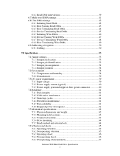
...53 7.1 Jumper settings 53 7.1.1 Jumper pin location 53 7.1.2 Jumper pin identification 53 7.1.3 Jumper pin assignment 54 7.1.4 Jumper positions 54 ...7.2 Environment 58 7.2.1 Temperature and humidity 58 7.2.2 Corrosion test 59 7.3 DC power requirements 59 7.3.1 Input voltage 59 7.3.2 Power supply current (typical 60 7.3.3 Power supply generated ripple at drive... hole locations 63 7.5.3 Connector locations 63 7.5.4 Drive mounting 64 7.5.5 Heads unload and actuator lock...
...53 7.1 Jumper settings 53 7.1.1 Jumper pin location 53 7.1.2 Jumper pin identification 53 7.1.3 Jumper pin assignment 54 7.1.4 Jumper positions 54 ...7.2 Environment 58 7.2.1 Temperature and humidity 58 7.2.2 Corrosion test 59 7.3 DC power requirements 59 7.3.1 Input voltage 59 7.3.2 Power supply current (typical 60 7.3.3 Power supply generated ripple at drive... hole locations 63 7.5.3 Connector locations 63 7.5.4 Drive mounting 64 7.5.5 Heads unload and actuator lock...
Specifications
Page 58
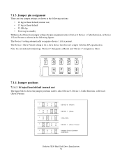
...HFDB IGECA HFDB IGECA HFDB IGECA H F D B DEVICE 0 (Master) DEVICE 1 (Slave) CABLE SEL DEVICE 1 (Slave) Present Shipping Default Condition (DEVICE 0) Deskstar 7K80 Hard Disk Drive Specification 54 The Device 0 setting automatically recognizes device 1 if it is for a slave device that does not comply with the ATA specification...I GECA HFDB DS CS/SP GND RSV 7.1.4 Jumper positions 7.1.4.1 16 logical head default (normal use ) • 15 logical head default • 32 GB clip • Power up in standby Within each of these four jumper settings the pin assignment selects Device 0, Device ...
...HFDB IGECA HFDB IGECA HFDB IGECA H F D B DEVICE 0 (Master) DEVICE 1 (Slave) CABLE SEL DEVICE 1 (Slave) Present Shipping Default Condition (DEVICE 0) Deskstar 7K80 Hard Disk Drive Specification 54 The Device 0 setting automatically recognizes device 1 if it is for a slave device that does not comply with the ATA specification...I GECA HFDB DS CS/SP GND RSV 7.1.4 Jumper positions 7.1.4.1 16 logical head default (normal use ) • 15 logical head default • 32 GB clip • Power up in standby Within each of these four jumper settings the pin assignment selects Device 0, Device ...
Specifications
Page 59
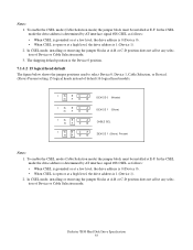
... logical head default The figure below shows the jumper positions used to select Device 0, Device 1, Cable Selection, or Device1 (Slave) Present setting 15 logical heads instead of Device or Cable Selection mode. Deskstar 7K80 Hard Disk Drive Specification 55 In CSEL mode, installing or removing the jumper blocks at A-B or C-D position does not affect any...
... logical head default The figure below shows the jumper positions used to select Device 0, Device 1, Cable Selection, or Device1 (Slave) Present setting 15 logical heads instead of Device or Cable Selection mode. Deskstar 7K80 Hard Disk Drive Specification 55 In CSEL mode, installing or removing the jumper blocks at A-B or C-D position does not affect any...
Specifications
Page 60
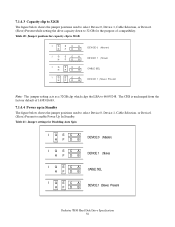
... 1 (Slave) CABLE SEL DEVICE 1 (Slave) Present Note: The jumper setting acts as a 32GB clip which clips the LBA to 32 GB for Disabling Auto Spin I GECA HFDB DEVICE 0 (Master) I GECA HFDB DEVICE 1 (Slave) I GECA HFDB CABLE SEL I GECA HFDB DEVICE 1 (Slave) Present Deskstar 7K80 Hard Disk Drive Specification 56 The CHS is unchanged from the...
... 1 (Slave) CABLE SEL DEVICE 1 (Slave) Present Note: The jumper setting acts as a 32GB clip which clips the LBA to 32 GB for Disabling Auto Spin I GECA HFDB DEVICE 0 (Master) I GECA HFDB DEVICE 1 (Slave) I GECA HFDB CABLE SEL I GECA HFDB DEVICE 1 (Slave) Present Deskstar 7K80 Hard Disk Drive Specification 56 The CHS is unchanged from the...
Specifications
Page 61
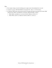
... Notes: 1. To enable the CSEL mode (Cable Selection mode) the jumper block must be installed at a high level, the drive address is SET FEATURES (subcommand 07h). Command to 12.28 Set Features. 3. In the CSEL mode the drive address is determined by AT interface signal #28 CSEL as follows: &#...8226; When CSEL is grounded or at a low level, the drive address is 0 (Device 0). • When CSEL is open or at E-F. Refer to spin up is 1 (Device 1). Deskstar 7K80 Hard Disk Drive Specification 57
... Notes: 1. To enable the CSEL mode (Cable Selection mode) the jumper block must be installed at a high level, the drive address is SET FEATURES (subcommand 07h). Command to 12.28 Set Features. 3. In the CSEL mode the drive address is determined by AT interface signal #28 CSEL as follows: &#...8226; When CSEL is grounded or at a low level, the drive address is 0 (Device 0). • When CSEL is open or at E-F. Refer to spin up is 1 (Device 1). Deskstar 7K80 Hard Disk Drive Specification 57
Specifications
Page 72
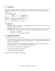
... drive serial number • A label containing jumper ...pin description • A user designed label per agreement The above labels may be integrated with the following formula: • Dwell time = 0.5 x 60/RPM • Seek rate = 0.4 / (average seek time + dwell time) 7.8 Identification labels The following labels are affixed to every drive: • A label containing the Hitachi logo, the Hitachi... Global Storage Technologies part number and the statement " Made by Hitachi... Idle mode: The drive is powered on, disks spinning...
... drive serial number • A label containing jumper ...pin description • A user designed label per agreement The above labels may be integrated with the following formula: • Dwell time = 0.5 x 60/RPM • Seek rate = 0.4 / (average seek time + dwell time) 7.8 Identification labels The following labels are affixed to every drive: • A label containing the Hitachi logo, the Hitachi... Global Storage Technologies part number and the statement " Made by Hitachi... Idle mode: The drive is powered on, disks spinning...

Specifications
Page 105
... in Standby feature set The Power-Up In Standby feature set allows devices to be disabled via the SET FEATURES command or the use of a jumper. A device needs a SET FEATURES subcommand to spin-up to active state when the device has powered up into Standby. If power-up into ...8226; this feature set is enabled or disabled • the device needs the Set Features command to spin-up into active state Deskstar 7K80 Hard Disk Drive Specification 101 When enabled by a jumper, the feature set shall not be powered-up into Standby, the device shall set word 0 bit 2 to one to sequence the...
... in Standby feature set The Power-Up In Standby feature set allows devices to be disabled via the SET FEATURES command or the use of a jumper. A device needs a SET FEATURES subcommand to spin-up to active state when the device has powered up into Standby. If power-up into ...8226; this feature set is enabled or disabled • the device needs the Set Features command to spin-up into active state Deskstar 7K80 Hard Disk Drive Specification 101 When enabled by a jumper, the feature set shall not be powered-up into Standby, the device shall set word 0 bit 2 to one to sequence the...
Specifications
Page 145
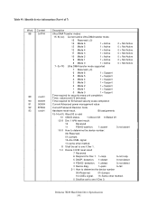
.... 1=detect 0=not detect 4 PDIAG- detection. 1=detect 0=not detect 3 Device diag. 1=pass 0=fail 2-1 How to determine the device number 00=Reserved. 01=Jumper. 10=CSEL signal. 11=Some other method. 8 Shall be set to one if Dev 1. 7-0 Device 0 H/W reset result 7 Reserved 6 Respond for Enhanced ...-8 Dev 1 H/W reset result. 12 Reserved 11 PDIAG-asertion. 1=assert 0=not assert 10-9 How to determine the device number: 00=Reserved. 01=Jumper. 10=the CSEL signal. 11=some other method. 0 Shall be set to one if Dev 0. Deskstar 7K80 Hard Disk Drive Specification 141
.... 1=detect 0=not detect 4 PDIAG- detection. 1=detect 0=not detect 3 Device diag. 1=pass 0=fail 2-1 How to determine the device number 00=Reserved. 01=Jumper. 10=CSEL signal. 11=Some other method. 8 Shall be set to one if Dev 1. 7-0 Device 0 H/W reset result 7 Reserved 6 Respond for Enhanced ...-8 Dev 1 H/W reset result. 12 Reserved 11 PDIAG-asertion. 1=assert 0=not assert 10-9 How to determine the device number: 00=Reserved. 01=Jumper. 10=the CSEL signal. 11=some other method. 0 Shall be set to one if Dev 0. Deskstar 7K80 Hard Disk Drive Specification 141


