
User Manual
Page 4
... support devices or systems or other objects. Safety Instructions Caution 1. Also, pins or HDA corners may cause catastrophic failures. Hot swapping (Power-on usage conditions, please consult our sales or application engineers. 7. Voltage rise time 5 - 100 ms at power off. 11. If non-recommended size screws and torque are not kept within specifications (Power Supply, Environment, etc.). Warranty void in permanent damage to the drive...
... support devices or systems or other objects. Safety Instructions Caution 1. Also, pins or HDA corners may cause catastrophic failures. Hot swapping (Power-on usage conditions, please consult our sales or application engineers. 7. Voltage rise time 5 - 100 ms at power off. 11. If non-recommended size screws and torque are not kept within specifications (Power Supply, Environment, etc.). Warranty void in permanent damage to the drive...
User Manual
Page 9
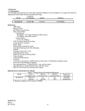
...Low Power Consumption: 0.85W(170mA) at Idle mode, 0.15W(30mA) at Standby mode - Read-ahead Cache/Write Cache - SMART - Word 60•61 Total LBA 78140160 (04A85300h) K6602743 Rev.2 02.12.'02 - 9 - 1.0 General 1.1 Introduction The DK23EB series disk drives reach high capacities (40GB for Setup] Table 1.1 Identify Device information (Addressing) Model Word 1 Word 3 Word 6 Number of SPT DK23EB-40 16383 (*1) 16 63 (3FFFh) (0010h) (3Fh) *1. Capacity Model (Formatted) Height Interface DK23EB-40 40.007 GB 9.5 mm ATA-5(IDE) [Features] - Data Transfer Rate...
...Low Power Consumption: 0.85W(170mA) at Idle mode, 0.15W(30mA) at Standby mode - Read-ahead Cache/Write Cache - SMART - Word 60•61 Total LBA 78140160 (04A85300h) K6602743 Rev.2 02.12.'02 - 9 - 1.0 General 1.1 Introduction The DK23EB series disk drives reach high capacities (40GB for Setup] Table 1.1 Identify Device information (Addressing) Model Word 1 Word 3 Word 6 Number of SPT DK23EB-40 16383 (*1) 16 63 (3FFFh) (0010h) (3Fh) *1. Capacity Model (Formatted) Height Interface DK23EB-40 40.007 GB 9.5 mm ATA-5(IDE) [Features] - Data Transfer Rate...

User Manual
Page 16
....'02 - 16 - Seek rate = 0.4/(average access time + average latency) = 0.4/(average access time + 60/RPM/2) *5 : Caution Data reliability is stopped during power on hours (POH) : Less than 20% of side mounting holes) should be less than 50 mAp-p (Frequency Range: less than 500mVp-p. Grounding noise should be less than 20MHz). At seek mode, randomly select a cylinder and seek operation of the drive. Since reliability and product life depends on...
....'02 - 16 - Seek rate = 0.4/(average access time + average latency) = 0.4/(average access time + 60/RPM/2) *5 : Caution Data reliability is stopped during power on hours (POH) : Less than 20% of side mounting holes) should be less than 50 mAp-p (Frequency Range: less than 500mVp-p. Grounding noise should be less than 20MHz). At seek mode, randomly select a cylinder and seek operation of the drive. Since reliability and product life depends on...

User Manual
Page 17
... load/unload operations are unloaded by the software control after power off, the heads are limited to over 30 sec by the Host side. [Sequence #3]: Power off the drive Above sequence is automatically performed by control software, during HDD life. Since normal unload can not be set to maximum 300,000 times during Idle mode. Standby - Standby Immediate - Standby Immediate - The maximum number of following commands. -
... load/unload operations are unloaded by the software control after power off, the heads are limited to over 30 sec by the Host side. [Sequence #3]: Power off the drive Above sequence is automatically performed by control software, during HDD life. Since normal unload can not be set to maximum 300,000 times during Idle mode. Standby - Standby Immediate - Standby Immediate - The maximum number of following commands. -

User Manual
Page 35
...V V Write Commands Write Buffer PO 2 E8h D Write Sectors PO 2 30h, 31h V V V V Write Long PO 2 32h, 33h V V V V Write Multiple PO 3 C5h V V V V Write DMA DM 3 CAh,CBh V V V V Format Track PO 2 50h V V V Flush Cache ND 1 E7h D Seek Commands Recalibrate ND 1 1Xh D Seek ND 1 7Xh V V V Mode Set/Check, Diagnostic Execute Device Diagnostic ND 1 90h D Initialize Device Parameters ND 1 91h V V Identify Device PI 1 ECh D Set Features ND 1 EFh V D Set Multiple Mode ND 1 C6h V D Power Control Check Power Mode ND...
...V V Write Commands Write Buffer PO 2 E8h D Write Sectors PO 2 30h, 31h V V V V Write Long PO 2 32h, 33h V V V V Write Multiple PO 3 C5h V V V V Write DMA DM 3 CAh,CBh V V V V Format Track PO 2 50h V V V Flush Cache ND 1 E7h D Seek Commands Recalibrate ND 1 1Xh D Seek ND 1 7Xh V V V Mode Set/Check, Diagnostic Execute Device Diagnostic ND 1 90h D Initialize Device Parameters ND 1 91h V V Identify Device PI 1 ECh D Set Features ND 1 EFh V D Set Multiple Mode ND 1 C6h V D Power Control Check Power Mode ND...

User Manual
Page 40
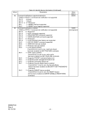
... 81 ATA Interface Minor Version Number 82 Command Set Supported 0000h or FFFFh = Command set notification not supported Bit 15 0 = Reserved Bit 14 1 = NOP command supported Bit 13 1 = READ BUFFER command supported Bit 12 1 = WRITE BUFFER command supported Bit 11 0 = Reserved Bit 10 1 = Host Protected Area feature set supported Bit 9 1 = DEVICE RESET command supported Bit 8 1 = SERVICE interrupt supported Bit 7 1 = Release interrupt supported Bit 6 1 = Look-ahead supported Bit 5 1 = Write cache supported Bit 4 1 = Supports PACKET command feature set Bit 3 1 = Supports power...
... 81 ATA Interface Minor Version Number 82 Command Set Supported 0000h or FFFFh = Command set notification not supported Bit 15 0 = Reserved Bit 14 1 = NOP command supported Bit 13 1 = READ BUFFER command supported Bit 12 1 = WRITE BUFFER command supported Bit 11 0 = Reserved Bit 10 1 = Host Protected Area feature set supported Bit 9 1 = DEVICE RESET command supported Bit 8 1 = SERVICE interrupt supported Bit 7 1 = Release interrupt supported Bit 6 1 = Look-ahead supported Bit 5 1 = Write cache supported Bit 4 1 = Supports PACKET command feature set Bit 3 1 = Supports power...
User Manual
Page 41
... 5 1 = Write cache enabled If word 85 bit 5 is set to one, the SMART feature set has been enabled via SMART ENABLE OPERATIONS command. Bit 4 1 = Supports PACKET command feature set Bit 3 1 = Supports power management feature set Bit 2 1 = Supports removable feature set Bit 1 1 = Supports Security Mode feature enabled If word 85 bit 1 is set to one, read look-ahead has been enabled via SET FEATURE command. Value (HEX.) 4003h 7468h (at shipment) K6602743 Rev.2 02.12.'02 - 41 - Word Table 6.5 Identify Device Information...
... 5 1 = Write cache enabled If word 85 bit 5 is set to one, the SMART feature set has been enabled via SMART ENABLE OPERATIONS command. Bit 4 1 = Supports PACKET command feature set Bit 3 1 = Supports power management feature set Bit 2 1 = Supports removable feature set Bit 1 1 = Supports Security Mode feature enabled If word 85 bit 1 is set to one, read look-ahead has been enabled via SET FEATURE command. Value (HEX.) 4003h 7468h (at shipment) K6602743 Rev.2 02.12.'02 - 41 - Word Table 6.5 Identify Device Information...
User Manual
Page 44
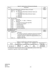
... 2 Word 3 Number of user addressable sectors in word 255. Number of HD Number of SPT 16383 *2 16 63 (3FFFh) (0010h) (3Fh) Word 60•61 *1 Total LBA 78,140,160 (4A8 5300h) *1: Words 60-61 reflect the total number of CYL. Maximum capacity in CHS mode is ignored. Word Table 6.5 Identify Device Information(Continued) Description 127 Removable Media Status Notification feature set support Bit...
... 2 Word 3 Number of user addressable sectors in word 255. Number of HD Number of SPT 16383 *2 16 63 (3FFFh) (0010h) (3Fh) Word 60•61 *1 Total LBA 78,140,160 (4A8 5300h) *1: Words 60-61 reflect the total number of CYL. Maximum capacity in CHS mode is ignored. Word Table 6.5 Identify Device Information(Continued) Description 127 Removable Media Status Notification feature set support Bit...

User Manual
Page 45
... contains the number of sectors to be 4 Bytes (Default). An implied seek is issued, the device sets BSY, sets up to 512 bytes of corrupted data, if any. At command completion, the Command Block Registers contain the cylinder, head, and sector numbers of the device's sector buffer. 6.3.2.3.2 Read Buffer [E4h] The Read Buffer command enables the host to read the current contents of the last sector read. The host then reads up the sector buffer...
... contains the number of sectors to be 4 Bytes (Default). An implied seek is issued, the device sets BSY, sets up to 512 bytes of corrupted data, if any. At command completion, the Command Block Registers contain the cylinder, head, and sector numbers of the device's sector buffer. 6.3.2.3.2 Read Buffer [E4h] The Read Buffer command enables the host to read the current contents of the last sector read. The host then reads up the sector buffer...

User Manual
Page 46
... operations are made to try and read . 6.3.2.4.2 Write Sectors [30h, 31h] This command writes sectors as specified in the sector buffer is similar to the Write Sectors command, except that it writes the data and the ECC bytes directly from the host to the device. 1) The host writes any required parameters to the Features, Sector Count, Sector Number, Cylinder Low, Cylinder High, and Device/Head Registers. 2) The host writes the command code to the Command Register. 3) The device sets...
... operations are made to try and read . 6.3.2.4.2 Write Sectors [30h, 31h] This command writes sectors as specified in the sector buffer is similar to the Write Sectors command, except that it writes the data and the ECC bytes directly from the host to the device. 1) The host writes any required parameters to the Features, Sector Count, Sector Number, Cylinder Low, Cylinder High, and Device/Head Registers. 2) The host writes the command code to the Command Register. 3) The device sets...

User Manual
Page 47
... number of sectors per track and the number of sectors to mark a sector as follows. If the device is not in the Physical mode, but the Physical mode is used only in the Physical mode, the device executes a vendor specific operation. 6.3.2.5 Non-Data Commands Execution of these commands does not involve any data transfer. 1) The host writes any required parameters to the registers. 2) The host writes the command code to the Command Registers. 3) The device sets...
... number of sectors per track and the number of sectors to mark a sector as follows. If the device is not in the Physical mode, but the Physical mode is used only in the Physical mode, the device executes a vendor specific operation. 6.3.2.5 Non-Data Commands Execution of these commands does not involve any data transfer. 1) The host writes any required parameters to the registers. 2) The host writes the command code to the Command Registers. 3) The device sets...

User Manual
Page 48
... Mode *4 Enable retries Enable read look-ahead feature Enable 4 bytes ECC transfer Enable reverting to power on defaults Enable write cache Disable write cache Default √ √ *1: If the code is posted. 6.3.2.5.4 Seek [7Xh] This command indicates a logical seek to the track and head specified in Tables 6.7 and 6.8. 6.3.2.5.2 Read Verify [40h, 41h] This command is same as the Read Sectors command, except that DRQ is never set DSC=1 after the seek has Completed. The device will set and no data is used...
... Mode *4 Enable retries Enable read look-ahead feature Enable 4 bytes ECC transfer Enable reverting to power on defaults Enable write cache Disable write cache Default √ √ *1: If the code is posted. 6.3.2.5.4 Seek [7Xh] This command indicates a logical seek to the track and head specified in Tables 6.7 and 6.8. 6.3.2.5.2 Read Verify [40h, 41h] This command is same as the Read Sectors command, except that DRQ is never set DSC=1 after the seek has Completed. The device will set and no data is used...

User Manual
Page 49
... default mode at power on or after a hardware reset. 6.3.2.5.7 Execute device diagnostic [90h] This command allows the device to perform Read Multiple and Write Multiple operations. Block sizes of 2, 4, 8, and 16 sectors are connected in the Error register, clears BSY, and generates an interrupt. When DRV0 and DRV1 are supported. Then the device registers the diagnostic result in the daisy chain mode, this command, it sets BSY=1 and executes the self-diagnostic operation. Table 6.9 Diagnostic Codes Code...
... default mode at power on or after a hardware reset. 6.3.2.5.7 Execute device diagnostic [90h] This command allows the device to perform Read Multiple and Write Multiple operations. Block sizes of 2, 4, 8, and 16 sectors are connected in the Error register, clears BSY, and generates an interrupt. When DRV0 and DRV1 are supported. Then the device registers the diagnostic result in the daisy chain mode, this command, it sets BSY=1 and executes the self-diagnostic operation. Table 6.9 Diagnostic Codes Code...
User Manual
Page 57
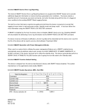
... at all error log data will be reset to zero by the host, the device does not disable SMART device error log. If SMART is disabled by client software "Download Utility". 6.3.2.8.3 SMART Operation with Power Management Modes When used in reduced power modes "standby mode and sleep mode". If the device has been set , a SMART enabled device automatically saves its attribute values upon receipt of an IDLE IMMEDIATE, STANDBY IMMEDIATE, or SLEEP command. Disabling SMART will be discarded and the device error count for...
... at all error log data will be reset to zero by the host, the device does not disable SMART device error log. If SMART is disabled by client software "Download Utility". 6.3.2.8.3 SMART Operation with Power Management Modes When used in reduced power modes "standby mode and sleep mode". If the device has been set , a SMART enabled device automatically saves its attribute values upon receipt of an IDLE IMMEDIATE, STANDBY IMMEDIATE, or SLEEP command. Disabling SMART will be discarded and the device error count for...

User Manual
Page 74
... unlock the device. The security level is revised. The password supplied with the command shall be saved as the new user password. Master password revision code set master password shall then unlock the device. The lock function shall be unlocked by only the user password. The device shall then be enabled from the next power-on or hardware reset. The master password previously set a master password but shall not be saved as the new user password. Device returns Aborted command error if the device is returned in Locked mode...
... unlock the device. The security level is revised. The password supplied with the command shall be saved as the new user password. Master password revision code set master password shall then unlock the device. The lock function shall be unlocked by only the user password. The device shall then be enabled from the next power-on or hardware reset. The master password previously set a master password but shall not be saved as the new user password. Device returns Aborted command error if the device is returned in Locked mode...

User Manual
Page 76
... device rejects the command with an Aborted error. If the device receives a Security Erase Unit command without an immediately prior Security Erase Prepare command, the device aborts the Security Erase unit command This command disables the device lock function, however, the master password is still stored internally within the device and may be reactivated later when a new user password is in Frozen mode. 6.3.2.9.8 Security Erase Unit [F4h] This command requests a transfer of a single sector of the device. The execution time of information. DK23EB-40 Identify Device...
... device rejects the command with an Aborted error. If the device receives a Security Erase Unit command without an immediately prior Security Erase Prepare command, the device aborts the Security Erase unit command This command disables the device lock function, however, the master password is still stored internally within the device and may be reactivated later when a new user password is in Frozen mode. 6.3.2.9.8 Security Erase Unit [F4h] This command requests a transfer of a single sector of the device. The execution time of information. DK23EB-40 Identify Device...
User Manual
Page 78
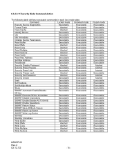
...Sectors Aborted Executable Read Verify Aborted Executable Read Max Address Executable Executable Set Max Address Executable Executable Recalibrate Executable Executable Security Disable Password Aborted Executable Security Erase Prepare Executable Executable Security Erase Unit Executable Executable Security Freeze Lock Aborted Executable Security Set Password Aborted Executable Security Unlock Executable Executable Seek Executable Executable Set Features Executable Executable Set Multiple Mode Executable Executable Sleep Executable Executable SMART...
...Sectors Aborted Executable Read Verify Aborted Executable Read Max Address Executable Executable Set Max Address Executable Executable Recalibrate Executable Executable Security Disable Password Aborted Executable Security Erase Prepare Executable Executable Security Erase Unit Executable Executable Security Freeze Lock Aborted Executable Security Set Password Aborted Executable Security Unlock Executable Executable Seek Executable Executable Set Features Executable Executable Set Multiple Mode Executable Executable Sleep Executable Executable SMART...

User Manual
Page 80
... the Set Max Frozen mode. 6.3.2.10.2 Address Offset Feature Computer systems perform initial code booting by Set Feature Command Subcommand 89h "Disable Address Offset Mode", Software Reset, Hardware Reset or Power on disk drive, Address Offset Feature provides a Set Feature function to the start of a non-volatile reserved area established using the address returned by an Set Max Address command to move the Set Max pointer to the size specified in the Identify Device data is set...
... the Set Max Frozen mode. 6.3.2.10.2 Address Offset Feature Computer systems perform initial code booting by Set Feature Command Subcommand 89h "Disable Address Offset Mode", Software Reset, Hardware Reset or Power on disk drive, Address Offset Feature provides a Set Feature function to the start of a non-volatile reserved area established using the address returned by an Set Max Address command to move the Set Max pointer to the size specified in the Identify Device data is set...
User Manual
Page 87
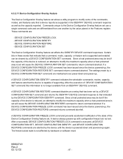
...maximum capacity when a host protected area is set will cause the DEVICE CONFIGURATION RESTORE command to return command aborted. If a DEVICE CONFIGURATION FREEZE LOCK command has been issued since the device powered-up . Commands unique to the Device Configuration Overlay feature set use a single command code and are differentiated from an IDENTIFY DEVICE command. A DEVICE CONFIGURATION FREEZE LOCK command prevents accidental modification of the state of DEVICE CONFIGURATION SET command this information is no longer available from one another by a DEVICE CONFIGURATION SET command...
...maximum capacity when a host protected area is set will cause the DEVICE CONFIGURATION RESTORE command to return command aborted. If a DEVICE CONFIGURATION FREEZE LOCK command has been issued since the device powered-up . Commands unique to the Device Configuration Overlay feature set use a single command code and are differentiated from an IDENTIFY DEVICE command. A DEVICE CONFIGURATION FREEZE LOCK command prevents accidental modification of the state of DEVICE CONFIGURATION SET command this information is no longer available from one another by a DEVICE CONFIGURATION SET command...

User Manual
Page 88
..., Sub 00h] Task File Registers Command Cylinder High Cylinder Low Device/Head Sector Number Sector Count Features DRV : Device selection bit 7 6 5 4 3 2 1 0 B1h XX XX - After successful execution of a DEVICE CONFIGURATION IDENTIFY command. If DEVICE CONFIGURATION FREEZE LOCK is cleared by a power-down. The DEVICE CONFIGURATION FREEZE LOCK condition is set or if a host protected area has been set by the data returned from the execution of a DEVICE CONFIGURATION FREEZE LOCK command, all DEVICE CONFIGURATION SET, DEVICE CONFIGURATION FREEZE LOCK, DEVICE CONFIGURATION IDENTIFY, and...
..., Sub 00h] Task File Registers Command Cylinder High Cylinder Low Device/Head Sector Number Sector Count Features DRV : Device selection bit 7 6 5 4 3 2 1 0 B1h XX XX - After successful execution of a DEVICE CONFIGURATION IDENTIFY command. If DEVICE CONFIGURATION FREEZE LOCK is cleared by a power-down. The DEVICE CONFIGURATION FREEZE LOCK condition is set or if a host protected area has been set by the data returned from the execution of a DEVICE CONFIGURATION FREEZE LOCK command, all DEVICE CONFIGURATION SET, DEVICE CONFIGURATION FREEZE LOCK, DEVICE CONFIGURATION IDENTIFY, and...


