

Specifications
Page 7
... D9h] 58 6.3.2.8.7 SMART Return Status [B0h, Sub DAh] 59 6.3.2.8.8 SMART Enable/Disable Attribute AUTOSAVE [B0h, Sub D2h 59 6.3.2.8.9 SMART Save Attribute Values [B0h, Sub D3h] 60 6.3.2.8.10 SMART Enable/Disable Automatic Off-line [B0h, Sub DBh 61 6.3.2.8.11 SMART Execute Off-line Immediate [B0h, Sub D4h 62 K6602637 Rev.3 02.27.01...
... D9h] 58 6.3.2.8.7 SMART Return Status [B0h, Sub DAh] 59 6.3.2.8.8 SMART Enable/Disable Attribute AUTOSAVE [B0h, Sub D2h 59 6.3.2.8.9 SMART Save Attribute Values [B0h, Sub D3h] 60 6.3.2.8.10 SMART Enable/Disable Automatic Off-line [B0h, Sub DBh 61 6.3.2.8.11 SMART Execute Off-line Immediate [B0h, Sub D4h 62 K6602637 Rev.3 02.27.01...
Specifications
Page 9
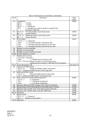
... CDR (Constant Density Recording) - On-the-fly ECC Correction - 1.0 General 1.1 Introduction The DK23CA series disk drives reach high capacities (30,005MB, 15,103MB and 7,501MB for Setup] Table 1.1 Identify Device information (Addressing...) Model Word 1 Word 3 Word 6 Word 60Ŋ61 Number of SPT Total LBA DK23CA-30F/30 16383 16 63 58605120 (3FFFh) (0010h) (3Fh) (037E3E40h) DK23CA-15 16383 16 63 29498112 (3FFFh) (0010h) (3Fh) (01C21B00h) DK23CA...
... CDR (Constant Density Recording) - On-the-fly ECC Correction - 1.0 General 1.1 Introduction The DK23CA series disk drives reach high capacities (30,005MB, 15,103MB and 7,501MB for Setup] Table 1.1 Identify Device information (Addressing...) Model Word 1 Word 3 Word 6 Word 60Ŋ61 Number of SPT Total LBA DK23CA-30F/30 16383 16 63 58605120 (3FFFh) (0010h) (3Fh) (037E3E40h) DK23CA-15 16383 16 63 29498112 (3FFFh) (0010h) (3Fh) (01C21B00h) DK23CA...
Specifications
Page 39
... setting is equal to or greater than 5 minutes. Word Table 6.5 Identify Device Information (Continued) Description 50 51 52 53 54 55 56 57-58 59 60-61 62 63 64 65 66 67 68 69-74 75 76-79 Capabilities Bit 15 0 (fixed) Bit 14 1 (fixed) Bit 13 - 1 0 = Reserved Bit 0 1 = Standby...
... setting is equal to or greater than 5 minutes. Word Table 6.5 Identify Device Information (Continued) Description 50 51 52 53 54 55 56 57-58 59 60-61 62 63 64 65 66 67 68 69-74 75 76-79 Capabilities Bit 15 0 (fixed) Bit 14 1 (fixed) Bit 13 - 1 0 = Reserved Bit 0 1 = Standby...
Specifications
Page 44
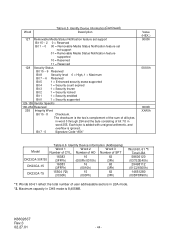
...) 16 (000Fh/0010h) 63 (3Fh) DK23CA-15 16383 (3FFFh) 16 (0010h) 63 (3Fh) DK23CA-75 15504 (*2) (3C90h) 15 (000Fh) 63 (3Fh) Word 60Ŋ61 *1 Total LBA 58605120 (037E3E40h) 29498112 (01C21B00h) 14651280 (00DF8F90h) *1: Words 60-61 reflect the total number of bit 7:0... set support Bit 15 - 2 0 = Reserved Bit 1 - 0 00 = Removable Media Status Notification feature set not support 01 = Removable Media Status Notification feature supported 10 = Reserved 11 = Reserved 128 Security Status Bit 15 - 9 Reserved Bit 8 Security level 0 = High, 1 = Maximum Bit 7 - 6 Reserved Bit 5 1...
...) 16 (000Fh/0010h) 63 (3Fh) DK23CA-15 16383 (3FFFh) 16 (0010h) 63 (3Fh) DK23CA-75 15504 (*2) (3C90h) 15 (000Fh) 63 (3Fh) Word 60Ŋ61 *1 Total LBA 58605120 (037E3E40h) 29498112 (01C21B00h) 14651280 (00DF8F90h) *1: Words 60-61 reflect the total number of bit 7:0... set support Bit 15 - 2 0 = Reserved Bit 1 - 0 00 = Removable Media Status Notification feature set not support 01 = Removable Media Status Notification feature supported 10 = Reserved 11 = Reserved 128 Security Status Bit 15 - 9 Reserved Bit 8 Security level 0 = High, 1 = Maximum Bit 7 - 6 Reserved Bit 5 1...
Specifications
Page 60
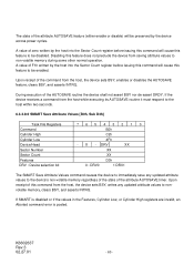
... Sector Count register before issuing this command will cause this feature to non-volatile memory during some other normal operation. K6602637 Rev.3 02.27.01 - 60 - If SMART is disabled or if the values in the Features, Cylinder Low, or Cylinder High registers are invalid, an Aborted command error is posted...
... Sector Count register before issuing this command will cause this feature to non-volatile memory during some other normal operation. K6602637 Rev.3 02.27.01 - 60 - If SMART is disabled or if the values in the Features, Cylinder Low, or Cylinder High registers are invalid, an Aborted command error is posted...
Specifications
Page 67
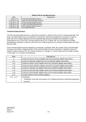
... of Cylinder Low register when the Command register was written. Byte n thru n+11 n+12 thru n+23 n+24 thru n+35 n+36 thru n+47 n+48 thru n+59 n+60 thru n+89 Table 6.14 Error log data structure Descriptions First command data structure Second command data structure Third command data structure Fourth command data structure...
... of Cylinder Low register when the Command register was written. Byte n thru n+11 n+12 thru n+23 n+24 thru n+35 n+36 thru n+47 n+48 thru n+59 n+60 thru n+89 Table 6.14 Error log data structure Descriptions First command data structure Second command data structure Third command data structure Fourth command data structure...
Specifications
Page 89
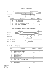
... *3 Data Consists of DD(15:0) SYMBOL Description t0 Cycle Time tC DMACK- Data Hold tI DMACK- Hold tS DIOR- to DIOR- / DIOW- MAX(ns) 80 60 Data Hold tG DIOW- Setup MIN(ns) 240 120 5 35 20 0 0 tD-tE K6602637 Rev.3 02.27.01 - 89 - Pulse Width tE DIOR- Setup tJ...
... *3 Data Consists of DD(15:0) SYMBOL Description t0 Cycle Time tC DMACK- Data Hold tI DMACK- Hold tS DIOR- to DIOR- / DIOW- MAX(ns) 80 60 Data Hold tG DIOW- Setup MIN(ns) 240 120 5 35 20 0 0 tD-tE K6602637 Rev.3 02.27.01 - 89 - Pulse Width tE DIOR- Setup tJ...
Specifications
Page 93
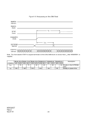
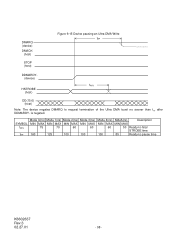
Figure 6-10 Host pausing an Ultra DMA Read DMARQ (device) DMACK(host) STOP tRP (host) HDMARDY(host) tRFS DSTROBE (device) DD(15:0) (device) Note: The host asserts STOP to -pause time K6602637 Rev.3 02.27.01 - 93 - SYMBOL tRFS tRP Mode 0(ns) Mode 1(ns) Mode 2(ns) Mode3(ns) MIN MAX MIN MAX MIN MAX MIN MAX 75 70 60 60 160 125 100 100 Mode4(ns) MIN MAX 60 100 Mode5(ns) Description MIN MAX 50 Ready-to-final STROBE time 85 Ready-to request termination of the Ultra DMA burst no sooner than tRP after HDMARDY- is negated.
Figure 6-10 Host pausing an Ultra DMA Read DMARQ (device) DMACK(host) STOP tRP (host) HDMARDY(host) tRFS DSTROBE (device) DD(15:0) (device) Note: The host asserts STOP to -pause time K6602637 Rev.3 02.27.01 - 93 - SYMBOL tRFS tRP Mode 0(ns) Mode 1(ns) Mode 2(ns) Mode3(ns) MIN MAX MIN MAX MIN MAX MIN MAX 75 70 60 60 160 125 100 100 Mode4(ns) MIN MAX 60 100 Mode5(ns) Description MIN MAX 50 Ready-to-final STROBE time 85 Ready-to request termination of the Ultra DMA burst no sooner than tRP after HDMARDY- is negated.
Specifications
Page 95
... sender tLI 0 150 0 150 0 150 0 100 0 100 0 75 Limited interlock time tMLI 20 20 20 20 20 20 Interlock time with minimum tAZ 10 10 10 10 10 10 Maximum time allowed for output drivers to -pause time tIORDYZ 20 20 20 20 20 20 Maximum time before releasing IORDY tACK 20 20 20... tACK tACK tIO R D Y Z D D (1 5 :0 ) tCVS CRC tCVH tACK DA0, DA1, DA2, CS0-, CS1- Note: The definitions for output drivers turning on tRFS 75 70 60 60 60 50 Ready-to-final-STROBE time tRP 160 125 100 100 100 85 Ready-to release tZAH 20 20 20 20 20 20 Minimum delay...
... sender tLI 0 150 0 150 0 150 0 100 0 100 0 75 Limited interlock time tMLI 20 20 20 20 20 20 Interlock time with minimum tAZ 10 10 10 10 10 10 Maximum time allowed for output drivers to -pause time tIORDYZ 20 20 20 20 20 20 Maximum time before releasing IORDY tACK 20 20 20... tACK tACK tIO R D Y Z D D (1 5 :0 ) tCVS CRC tCVH tACK DA0, DA1, DA2, CS0-, CS1- Note: The definitions for output drivers turning on tRFS 75 70 60 60 60 50 Ready-to-final-STROBE time tRP 160 125 100 100 100 85 Ready-to release tZAH 20 20 20 20 20 20 Minimum delay...
Specifications
Page 98
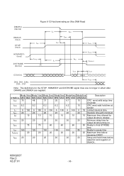
DMARQ (device) DMACK- (host) STOP (host) Figure 6-15 Device pausing an Ultra DMA Write tRP DDMARDY(device) tRFS HSTROBE (host) DD(15:0) (host) Note: The device negates DMARQ to -pause time K6602637 Rev.3 02.27.01 - 98 - is negated. SYMBOL tRFS tRP Mode 0(ns) Mode 1(ns) Mode 2(ns) MIN MAX MIN MAX MIN MAX 75 70 60 160 125 100 Mode 3(ns) MIN MAX 60 100 Mode 4(ns) MIN MAX 60 100 Mde5(ns) Description MIN MAX 50 Ready-to-final STROBE time 85 Ready-to request termination of the Ultra DMA burst no sooner than tRP after DDMARDY-
DMARQ (device) DMACK- (host) STOP (host) Figure 6-15 Device pausing an Ultra DMA Write tRP DDMARDY(device) tRFS HSTROBE (host) DD(15:0) (host) Note: The device negates DMARQ to -pause time K6602637 Rev.3 02.27.01 - 98 - is negated. SYMBOL tRFS tRP Mode 0(ns) Mode 1(ns) Mode 2(ns) MIN MAX MIN MAX MIN MAX 75 70 60 160 125 100 Mode 3(ns) MIN MAX 60 100 Mode 4(ns) MIN MAX 60 100 Mde5(ns) Description MIN MAX 50 Ready-to-final STROBE time 85 Ready-to request termination of the Ultra DMA burst no sooner than tRP after DDMARDY-

Specifications
Page 100
...) Mode5(ns) Description SYMBOL MIN MAX MIN MAX MIN MAX MIN MAX MIN MAX MIN MAX tCVS 70 48 31 20 6.7 10 CRC word valid setup time at sender tCVH 6.2 6.2 6.2 6.2 6.2 10 CRC word valid hold time at sender tLI 0 150 0 150 0 150 0 100 0 100 0 75 Limited interlock time tMLI 20... 20 20 20 20 20 Interlock time with minimum tRFS 75 70 60 60 60 50 Ready-to -pause time tIORDYZ 20 20 20 20 20...
...) Mode5(ns) Description SYMBOL MIN MAX MIN MAX MIN MAX MIN MAX MIN MAX MIN MAX tCVS 70 48 31 20 6.7 10 CRC word valid setup time at sender tCVH 6.2 6.2 6.2 6.2 6.2 10 CRC word valid hold time at sender tLI 0 150 0 150 0 150 0 100 0 100 0 75 Limited interlock time tMLI 20... 20 20 20 20 20 Interlock time with minimum tRFS 75 70 60 60 60 50 Ready-to -pause time tIORDYZ 20 20 20 20 20...