
Specifications
Page 5
...without power on the disk may be lost due to notify any purpose. K6602637 Rev.3 02.27.01 - 5 - To prepare for the drive transportation) 22. Hitachi does not perform data recovery. 24. Safety Instructions (Continued) Caution 19. Data may be lost due to notify us in a box. 21...information provided herein is packed in the event of such revisions or changes. Recorded data on should not exceed one year. 20. Prevent humidity when the drive is correct please feel free to accidents such as disasters, shock damage during write operation. The long-term storage without ...
...without power on the disk may be lost due to notify any purpose. K6602637 Rev.3 02.27.01 - 5 - To prepare for the drive transportation) 22. Hitachi does not perform data recovery. 24. Safety Instructions (Continued) Caution 19. Data may be lost due to notify us in a box. 21...information provided herein is packed in the event of such revisions or changes. Recorded data on should not exceed one year. 20. Prevent humidity when the drive is correct please feel free to accidents such as disasters, shock damage during write operation. The long-term storage without ...
Specifications
Page 6
...Off Sequence 4.0 Installation 4.1 Installation Direction 4.2 Mounting HDD 4.2.1 Mounting HDD with Screws 4.2.2 Single HDD Test Condition 4.2.3 Attention for HDD Installation 4.3 Drive Address Setting(DRIVE 0/DRIVE 1) 4.4 Dimensions 5.0 Packing and Handling 5.1 Packing 5.2 Handling 6.0 Interface 6.1 Power Interface 6.2 Physical Interface 6.2.1 Connector 6.2.2 Connector Pin Assignment ... Rev.3 02.27.01 - 6 - Page 2 9 9 10 12 13 13 15 16 17 17 17 17 18 18 19 19 20 21 21 22 23 23 24 25 25 26 26 27 28...
...Off Sequence 4.0 Installation 4.1 Installation Direction 4.2 Mounting HDD 4.2.1 Mounting HDD with Screws 4.2.2 Single HDD Test Condition 4.2.3 Attention for HDD Installation 4.3 Drive Address Setting(DRIVE 0/DRIVE 1) 4.4 Dimensions 5.0 Packing and Handling 5.1 Packing 5.2 Handling 6.0 Interface 6.1 Power Interface 6.2 Physical Interface 6.2.1 Connector 6.2.2 Connector Pin Assignment ... Rev.3 02.27.01 - 6 - Page 2 9 9 10 12 13 13 15 16 17 17 17 17 18 18 19 19 20 21 21 22 23 23 24 25 25 26 26 27 28...
Specifications
Page 14
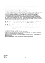
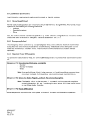
...is recommended at 5 minutes later after power-on. Secondary over current protection for the protection. *5 : For more information, refer to 20 seconds in which the power voltage and the temperature are unloaded. *7: Power mode automatically enters to circuit or component failure. This maximum... revolution times (i.e. When this power transition. *8 : Measured during start up, the drive may have some tolerance after Read/Write operation. The requirement of the current limitation is max. 10 A for possible combustion due to Low Power Active mode after power-on to Ready ...
...is recommended at 5 minutes later after power-on. Secondary over current protection for the protection. *5 : For more information, refer to 20 seconds in which the power voltage and the temperature are unloaded. *7: Power mode automatically enters to circuit or component failure. This maximum... revolution times (i.e. When this power transition. *8 : Measured during start up, the drive may have some tolerance after Read/Write operation. The requirement of the current limitation is max. 10 A for possible combustion due to Low Power Active mode after power-on to Ready ...
Specifications
Page 15
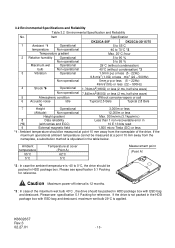
... Specification and Reliability No. Item Specification DK23CA-30F DK23CA-30/15/75 1 Ambient *1 Operational 5 to 55°C temperature Non-operational -40 to 70°C *2 Temperature gradient Max. 20°C /hour 2 Relative humidity Operational 5 to 90 % Non-operational 5 to 0°C, the drive should be packed in (*5) (with retries and ECC) 10 E 13 bits read 9 External magnetic...
... Specification and Reliability No. Item Specification DK23CA-30F DK23CA-30/15/75 1 Ambient *1 Operational 5 to 55°C temperature Non-operational -40 to 70°C *2 Temperature gradient Max. 20°C /hour 2 Relative humidity Operational 5 to 90 % Non-operational 5 to 0°C, the drive should be packed in (*5) (with retries and ECC) 10 E 13 bits read 9 External magnetic...
Specifications
Page 16
...The grounding current should be measured through 50 ohm resistor. -External Magnetic Field : Within specifications given in Table 3.1 "Principal Specifications" -Drive Grounding : Drive frame should be grounded to system ground with A-weighted . K6602637 Rev.3 02.27.01 - 16 - This value is stopped during ...is specified at power-on usage conditions, please consult our sales representatives or application engineers if the drive may be less than 50 mAp-p (Frequency Range: less than 20% of POH Read operations) -Motor Start/Stop Count : Max. 100,000 times. Clicking noise...
...The grounding current should be measured through 50 ohm resistor. -External Magnetic Field : Within specifications given in Table 3.1 "Principal Specifications" -Drive Grounding : Drive frame should be grounded to system ground with A-weighted . K6602637 Rev.3 02.27.01 - 16 - This value is stopped during ...is specified at power-on usage conditions, please consult our sales representatives or application engineers if the drive may be less than 50 mAp-p (Frequency Range: less than 20% of POH Read operations) -Motor Start/Stop Count : Max. 100,000 times. Clicking noise...
Specifications
Page 17
... To operate the load/unload normally, the following BIOS sequence is performed by Host system before power off , the heads are limited to maximum 20,000 times during Idle mode. Standby - Note: The head is automatically performed by the software control after power off . [Sequence #1]: Execute ...by unexpected power down, and is required for the Host system at Power off the drive Above sequence is limited to maximum 300,000 times during HDD life. Soft Reset does not unload the heads from DK23CA-xx. [Sequence #2]: Check the Status Register, and wait the command complete. K6602637...
... To operate the load/unload normally, the following BIOS sequence is performed by Host system before power off , the heads are limited to maximum 20,000 times during Idle mode. Standby - Note: The head is automatically performed by the software control after power off . [Sequence #1]: Execute ...by unexpected power down, and is required for the Host system at Power off the drive Above sequence is limited to maximum 300,000 times during HDD life. Soft Reset does not unload the heads from DK23CA-xx. [Sequence #2]: Check the Status Register, and wait the command complete. K6602637...
Specifications
Page 20
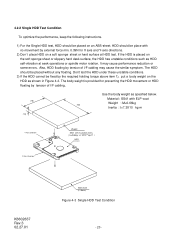
...tension of I =7.3X10⁻⁴ kg m2 ) HDD X Axis Direction K6602637 Rev.3 02.27.01 ABS-sheet (t = 5mm) Figure 4-3 Single HDD Test Condition - 20 - If the HDD is provided for X axis and Y-axis directions. 2) Don't place HDD on an ABS-sheet. Also, HDD floating by the required holding... torque above item 1), put a body weight on the soft sponge sheet or slippery hard desk surface, the HDD has unstable conditions such as specified below. 4.2.2 Single HDD Test Condition To optimize the performance, keep the following instructions....
...tension of I =7.3X10⁻⁴ kg m2 ) HDD X Axis Direction K6602637 Rev.3 02.27.01 ABS-sheet (t = 5mm) Figure 4-3 Single HDD Test Condition - 20 - If the HDD is provided for X axis and Y-axis directions. 2) Don't place HDD on an ABS-sheet. Also, HDD floating by the required holding... torque above item 1), put a body weight on the soft sponge sheet or slippery hard desk surface, the HDD has unstable conditions such as specified below. 4.2.2 Single HDD Test Condition To optimize the performance, keep the following instructions....
Specifications
Page 27
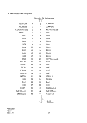
... DA0 35 CS0- 37 DASP- 39 5VDC(Logic) 41 GND(Logic) 43 B JUMPER0 D JUMPER2 F KEY(Removed) 2 GND 4 DD8 6 DD9 8 DD10 10 DD11 12 DD12 14 DD13 16 DD14 18 DD15 20 KEY(Removed) 22 GND 24 GND 26 GND 28 CSEL 30 GND 32 IOCS16- 34 PDIAG- 36 DA2 38 CS1- 40...
... DA0 35 CS0- 37 DASP- 39 5VDC(Logic) 41 GND(Logic) 43 B JUMPER0 D JUMPER2 F KEY(Removed) 2 GND 4 DD8 6 DD9 8 DD10 10 DD11 12 DD12 14 DD13 16 DD14 18 DD15 20 KEY(Removed) 22 GND 24 GND 26 GND 28 CSEL 30 GND 32 IOCS16- 34 PDIAG- 36 DA2 38 CS1- 40...

Specifications
Page 30
...this specification, it is ready to either acknowledge that data has been accepted, or that Drive 1 is present when the power is not within this signal. See Sec. 4.3 " Drive Address Setting (Drive 0/Drive 1)" for DMA data transfers between host and device, when it may cause factional degradations ... does not assert this signal. DMARQ DMACKJUMPER0,1,2 Pin 39 21 29 PIN-A,B,D I/O type I/O O I /F cable should be no longer than 50cm(20 inches) including the circuit pattern length in response to DMARQ to transfer data. The I/O signal levels are as follows. (1) Input signal High level ...
...this specification, it is ready to either acknowledge that data has been accepted, or that Drive 1 is present when the power is not within this signal. See Sec. 4.3 " Drive Address Setting (Drive 0/Drive 1)" for DMA data transfers between host and device, when it may cause factional degradations ... does not assert this signal. DMARQ DMACKJUMPER0,1,2 Pin 39 21 29 PIN-A,B,D I/O type I/O O I /F cable should be no longer than 50cm(20 inches) including the circuit pattern length in response to DMARQ to transfer data. The I/O signal levels are as follows. (1) Input signal High level ...
Specifications
Page 38
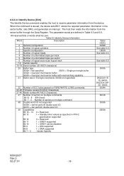
... Bit 8 1 = DMA supported Bit 7 - 0 Vendor Specific Value (HEX.) 045Ah See table 6.6 C837h See table 6.6 See table 6.6 0003h DK23CA-15/ 75: 0400h DK23CA-30F/ 30: 1000h 0004h 8010h 0000h 0B00h K6602637 Rev.3 02.27.01 - 38 - When the command is issued, the device sets BSY, stores...unformatted bytes per track 5 Number of unformatted bytes per sector 6 Number of logical sectors per logical track 7-9 Vendor specific 10-19 Serial number (20 ASCII characters) 20 Buffer type 0000h = Not specified 0001h = Single port single buffer 0002h = Dual port multi-sector buffer 0003h = Dual...
... Bit 8 1 = DMA supported Bit 7 - 0 Vendor Specific Value (HEX.) 045Ah See table 6.6 C837h See table 6.6 See table 6.6 0003h DK23CA-15/ 75: 0400h DK23CA-30F/ 30: 1000h 0004h 8010h 0000h 0B00h K6602637 Rev.3 02.27.01 - 38 - When the command is issued, the device sets BSY, stores...unformatted bytes per track 5 Number of unformatted bytes per sector 6 Number of logical sectors per logical track 7-9 Vendor specific 10-19 Serial number (20 ASCII characters) 20 Buffer type 0000h = Not specified 0001h = Single port single buffer 0002h = Dual port multi-sector buffer 0003h = Dual...
Specifications
Page 54
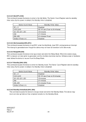
Sector Count Value SC = 0 0 The Sector Count Register sets the standby timer value. 6.3.2.6.4 Idle [97h, E3h] This command causes the device to enter to the Idle Mode. By the power on default, the Standby timer is disabled.
Sector Count Value SC = 0 0 The Sector Count Register sets the standby timer value. 6.3.2.6.4 Idle [97h, E3h] This command causes the device to enter to the Idle Mode. By the power on default, the Standby timer is disabled.

Specifications
Page 88
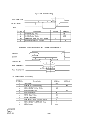
Data Setup 20 t6 DIOR- t2i t8 Write Data Valid *2 Read Data Valid *2 t7 IOCS16- Data Hold 10 t5 DIOR- Figure 6-4 PIO Data Transfer Timing(Mode 4) t0 Addr Valid *1 t1 t2 t9 DIOR-/DIOW- t3 t4 t5 t6 t6Z *1 Device Address consists ... IOCS16- Assertion(MAX) t8 Addr Valid To IOCS16- Data Hold 5 t6Z DIOR- Pulse Width 70 t2i DIOR-/DIOW- Setup 25 t2 DIOR-/DIOW- Data Setup 20 t4 DIOW- Negation (MAX) t9 DIOR-/DIOW- 6.4 Interface Signal Timing 6.4.1 Data Transfer Timing Figures 6-4, 6-5, 6-6 and 6-7 show the timing for asserting interface signals for ...
Data Setup 20 t6 DIOR- t2i t8 Write Data Valid *2 Read Data Valid *2 t7 IOCS16- Data Hold 10 t5 DIOR- Figure 6-4 PIO Data Transfer Timing(Mode 4) t0 Addr Valid *1 t1 t2 t9 DIOR-/DIOW- t3 t4 t5 t6 t6Z *1 Device Address consists ... IOCS16- Assertion(MAX) t8 Addr Valid To IOCS16- Data Hold 5 t6Z DIOR- Pulse Width 70 t2i DIOR-/DIOW- Setup 25 t2 DIOR-/DIOW- Data Setup 20 t4 DIOW- Negation (MAX) t9 DIOR-/DIOW- 6.4 Interface Signal Timing 6.4.1 Data Transfer Timing Figures 6-4, 6-5, 6-6 and 6-7 show the timing for asserting interface signals for ...
Specifications
Page 89
... IORDY Pulse Width tRD Read Data Valid to IORDY active tB IORDY assertion to DIOR- / DIOW- Hold tS DIOR- Setup MIN(ns) 240 120 5 35 20 0 0 tD-tE K6602637 Rev.3 02.27.01 - 89 -
... IORDY Pulse Width tRD Read Data Valid to IORDY active tB IORDY assertion to DIOR- / DIOW- Hold tS DIOR- Setup MIN(ns) 240 120 5 35 20 0 0 tD-tE K6602637 Rev.3 02.27.01 - 89 -
Specifications
Page 90
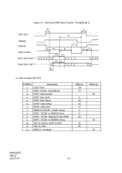
... tGr DIOR- Data Setup tGw DIOW- Negated Pulse Width tL DIOR- / DIOW- to DIOR- / DIOW- Data Hold tI DMACK to tristate MIN(ns) 120 70 5 20 20 10 0 5 25 25 25 MAX(ns) 50 35 25 K6602637 Rev.3 02.27.01 - 90 - Data Access tF DIOR- tN CS(1:0) hold tZ DMACK- Figure 6-7 Multi...
... tGr DIOR- Data Setup tGw DIOW- Negated Pulse Width tL DIOR- / DIOW- to DIOR- / DIOW- Data Hold tI DMACK to tristate MIN(ns) 120 70 5 20 20 10 0 5 25 25 25 MAX(ns) 50 35 25 K6602637 Rev.3 02.27.01 - 90 - Data Access tF DIOR- tN CS(1:0) hold tZ DMACK- Figure 6-7 Multi...

Specifications
Page 91
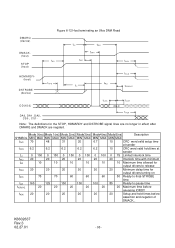
to-driving until the first transition of critical timing tACK 20 20 20 20 20 20 Setup and hold time at sender tFS 230 200 170 130 120 90 First strobe tUI 0 0 0 0 0 0 Unlimited interlock tAZ 10 10 10 10 10 10 Maximum time allowed for output drivers to release tZAD 0 0 0 0 0 0 Maximum delay time for the STOP, HDMARDY and DSTROBE signal lines are not in...
to-driving until the first transition of critical timing tACK 20 20 20 20 20 20 Setup and hold time at sender tFS 230 200 170 130 120 90 First strobe tUI 0 0 0 0 0 0 Unlimited interlock tAZ 10 10 10 10 10 10 Maximum time allowed for output drivers to release tZAD 0 0 0 0 0 0 Maximum delay time for the STOP, HDMARDY and DSTROBE signal lines are not in...

Specifications
Page 92
... 0(ns) Mode 1(ns) Mode 2(ns) Mode3(ns) MIN MAX MIN MAX MIN MAX MIN MAX 112 73 54 39 230 153 115 86 15 10 7 7 5 5 5 5 70 48 31 20 6.2 6.2 6.2 6.2 14.7 9.7 6.8 6.8 4.8 4.8 4.8 4.8 72.9 50.9 33.9 22.6 9.0 9.0 9.0 9.0 Mode4(ns) MIN MAX 25 57 5 5 6.7 6.2 4.8 4.8 9.5 9.0 Mode5(ns) MIN MAX 16.8 38 4 4.6 4.8 4.8 2.3 2.8 6.0 6.0 Description Cycle time allowing for asymmetry...
... 0(ns) Mode 1(ns) Mode 2(ns) Mode3(ns) MIN MAX MIN MAX MIN MAX MIN MAX 112 73 54 39 230 153 115 86 15 10 7 7 5 5 5 5 70 48 31 20 6.2 6.2 6.2 6.2 14.7 9.7 6.8 6.8 4.8 4.8 4.8 4.8 72.9 50.9 33.9 22.6 9.0 9.0 9.0 9.0 Mode4(ns) MIN MAX 25 57 5 5 6.7 6.2 4.8 4.8 9.5 9.0 Mode5(ns) MIN MAX 16.8 38 4 4.6 4.8 4.8 2.3 2.8 6.0 6.0 Description Cycle time allowing for asymmetry...

Specifications
Page 94
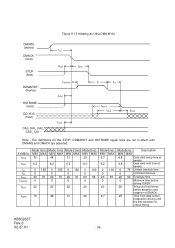
...0 150 0 150 0 150 0 100 0 100 0 75 Limited interlock time tMLI 20 20 20 20 20 20 Interlock time with minimum tAZ 10 10 10 10 10 10 Maximum time allowed for output drivers to release tZAH 20 20 20 20 20 20 Minimum delay time for the STOP, HDMARDY and DSTROBE signal lines are no longer in ... tACK DA0, DA1, DA2, CS0-, CS1- Note: The definitions for output drivers turning on tIORDYZ 20 20 20 20 20 20 Maximum time before releasing IORDY tACK 20 20 20 20 20 20 Setup and hold times before assertion and negation of DMACK_ tSS 50 50 50 50 50 50 Time ...
...0 150 0 150 0 150 0 100 0 100 0 75 Limited interlock time tMLI 20 20 20 20 20 20 Interlock time with minimum tAZ 10 10 10 10 10 10 Maximum time allowed for output drivers to release tZAH 20 20 20 20 20 20 Minimum delay time for the STOP, HDMARDY and DSTROBE signal lines are no longer in ... tACK DA0, DA1, DA2, CS0-, CS1- Note: The definitions for output drivers turning on tIORDYZ 20 20 20 20 20 20 Maximum time before releasing IORDY tACK 20 20 20 20 20 20 Setup and hold times before assertion and negation of DMACK_ tSS 50 50 50 50 50 50 Time ...
Specifications
Page 95
...tLI 0 150 0 150 0 150 0 100 0 100 0 75 Limited interlock time tMLI 20 20 20 20 20 20 Interlock time with minimum tAZ 10 10 10 10 10 10 Maximum time allowed for output drivers to release tZAH 20 20 20 20 20 20 Minimum delay time for the STOP, HDMARDY and DSTROBE signal lines are no longer in effect...to-final-STROBE time tRP 160 125 100 100 100 85 Ready-to-pause time tIORDYZ 20 20 20 20 20 20 Maximum time before releasing IORDY tACK 20 20 20 20 20 20 Setup and hold times before assertion and negation of DMACK_ K6602637 Rev.3 02.27.01 - 95 -...
...tLI 0 150 0 150 0 150 0 100 0 100 0 75 Limited interlock time tMLI 20 20 20 20 20 20 Interlock time with minimum tAZ 10 10 10 10 10 10 Maximum time allowed for output drivers to release tZAH 20 20 20 20 20 20 Minimum delay time for the STOP, HDMARDY and DSTROBE signal lines are no longer in effect...to-final-STROBE time tRP 160 125 100 100 100 85 Ready-to-pause time tIORDYZ 20 20 20 20 20 20 Maximum time before releasing IORDY tACK 20 20 20 20 20 20 Setup and hold times before assertion and negation of DMACK_ K6602637 Rev.3 02.27.01 - 95 -...
Specifications
Page 96
...0 150 0 150 0 0 0 20 70 20 70 20 70 0 0 0 tACK 20 20 20 tDZFS 70 48 31 Mode3(ns) MIN MAX 20 6.2 0 100 0 20 55 0 20 20 Mode4(ns) MIN MAX 6.7 6.2 0 100 0 20 55 0 20 6.7 Mode5(ns) Description MIN MAX ...4.8 Data valid setup time at sender 4.8 Data valid hold time at sender 0 75 Limited interlock time 0 Unlimited interlock 20 50 Envelope time 0 Minimum time before driving IORDY 20...
...0 150 0 150 0 0 0 20 70 20 70 20 70 0 0 0 tACK 20 20 20 tDZFS 70 48 31 Mode3(ns) MIN MAX 20 6.2 0 100 0 20 55 0 20 20 Mode4(ns) MIN MAX 6.7 6.2 0 100 0 20 55 0 20 6.7 Mode5(ns) Description MIN MAX ...4.8 Data valid setup time at sender 4.8 Data valid hold time at sender 0 75 Limited interlock time 0 Unlimited interlock 20 50 Envelope time 0 Minimum time before driving IORDY 20...

Specifications
Page 97
... clock variation t2CYC 230 153 115 86 57 38 Two cycle time allowing for clock variation tDS 15 10 7 7 5 4 Data setup time at recipient tDH 5 5 5 5 5 4.6 Data hold time at recipient tDVS 70 48 31 20 6.7 4.8 Data valid setup time at sender tDVH 6.2 6.2 6.2 6.2 6.2 4.8 Data valid hold time K6602637 Rev.3 02.27.01 - 97...
... clock variation t2CYC 230 153 115 86 57 38 Two cycle time allowing for clock variation tDS 15 10 7 7 5 4 Data setup time at recipient tDH 5 5 5 5 5 4.6 Data hold time at recipient tDVS 70 48 31 20 6.7 4.8 Data valid setup time at sender tDVH 6.2 6.2 6.2 6.2 6.2 4.8 Data valid hold time K6602637 Rev.3 02.27.01 - 97...