

Specifications
Page 2
... Rev.1: 02.08.01 Preliminary Rev.2: 02:15:01 Rev.3: 02:27:01 To use this manual and the product. Attention for drive usage in this manual with care to use . Follow all instructions and cautions described on this product. (Caution before attempting to insure ... cause bodily injury or damage to follow the instructions on "Safety Instructions" (Page 4) and "1.2 General Caution" (Page 10 and 11) before Product Use) - Keep this manual. General Caution - Handling Page 4 Sec. 1.2, Page 10 - 11 Sec.3.1, Page 14 Sec. 3.2, Page 15 Sec. 3.2, Page 16 Sec. 4.2.3, Page 21 Sec. 5.1, ...
... Rev.1: 02.08.01 Preliminary Rev.2: 02:15:01 Rev.3: 02:27:01 To use this manual and the product. Attention for drive usage in this manual with care to use . Follow all instructions and cautions described on this product. (Caution before attempting to insure ... cause bodily injury or damage to follow the instructions on "Safety Instructions" (Page 4) and "1.2 General Caution" (Page 10 and 11) before Product Use) - Keep this manual. General Caution - Handling Page 4 Sec. 1.2, Page 10 - 11 Sec.3.1, Page 14 Sec. 3.2, Page 15 Sec. 3.2, Page 16 Sec. 4.2.3, Page 21 Sec. 5.1, ...
Specifications
Page 4
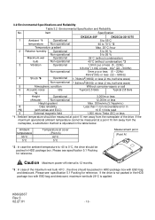
... may occur. 8. The power supply voltage must not be swapped during handling. 10. on HDD cover side, the spacing between HDD cover and steel plate should protect the drive from ESD during Power Off only. 9. Prevent shocks, which is max. 10 A for possible combustion due to active metal of the live metal, failures...
... may occur. 8. The power supply voltage must not be swapped during handling. 10. on HDD cover side, the spacing between HDD cover and steel plate should protect the drive from ESD during Power Off only. 9. Prevent shocks, which is max. 10 A for possible combustion due to active metal of the live metal, failures...
Specifications
Page 6
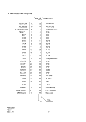
... HDD Installation 4.3 Drive Address Setting(DRIVE 0/DRIVE 1) 4.4 Dimensions... 5.0 Packing and Handling 5.1 Packing 5.2 Handling 6.0 Interface 6.1 Power Interface 6.2 Physical Interface 6.2.1 Connector 6.2.2 Connector Pin Assignment 6.2.3 Description of the Interface Signals 6.3 Logical Interface 6.3.1 I/O Registers 6.3.1.1 Data Register 6.3.1.2 Error Register 6.3.1.3 Features Register 6.3.1.4 Sector Count Register 6.3.1.5 Sector Number Register 6.3.1.6 Cylinder Low Register 6.3.1.7 Cylinder High Register 6.3.1.8 Device/Head Register 6.3.1.9 Status Register 6.3.1.10...
... HDD Installation 4.3 Drive Address Setting(DRIVE 0/DRIVE 1) 4.4 Dimensions... 5.0 Packing and Handling 5.1 Packing 5.2 Handling 6.0 Interface 6.1 Power Interface 6.2 Physical Interface 6.2.1 Connector 6.2.2 Connector Pin Assignment 6.2.3 Description of the Interface Signals 6.3 Logical Interface 6.3.1 I/O Registers 6.3.1.1 Data Register 6.3.1.2 Error Register 6.3.1.3 Features Register 6.3.1.4 Sector Count Register 6.3.1.5 Sector Number Register 6.3.1.6 Cylinder Low Register 6.3.1.7 Cylinder High Register 6.3.1.8 Device/Head Register 6.3.1.9 Status Register 6.3.1.10...

Specifications
Page 7
...] 58 6.3.2.8.7 SMART Return Status [B0h, Sub DAh] 59 6.3.2.8.8 SMART Enable/Disable Attribute AUTOSAVE [B0h, Sub D2h 59 6.3.2.8.9 SMART Save Attribute Values [B0h, Sub D3h] 60 6.3.2.8.10 SMART Enable/Disable Automatic Off-line [B0h, Sub DBh 61 6.3.2.8.11 SMART Execute Off-line Immediate [B0h, Sub D4h 62 K6602637 Rev.3 02.27.01...
...] 58 6.3.2.8.7 SMART Return Status [B0h, Sub DAh] 59 6.3.2.8.8 SMART Enable/Disable Attribute AUTOSAVE [B0h, Sub D2h 59 6.3.2.8.9 SMART Save Attribute Values [B0h, Sub D3h] 60 6.3.2.8.10 SMART Enable/Disable Automatic Off-line [B0h, Sub DBh 61 6.3.2.8.11 SMART Execute Off-line Immediate [B0h, Sub D4h 62 K6602637 Rev.3 02.27.01...
Specifications
Page 8
...] 77 6.3.2.9.11 Security Mode Command Action [F1h] 78 6.3.2.10 Protected Area Feature, Address Offset Feature 79 6.3.2.10.1 Protected Area Feature and Set Max Security Extension 79 6.3.2.10.2 Address Offset Feature 80 6.3.2.10.3 Read Max Address Command [F8h] 82 6.3.2.10.4 Set Max Address Command [F9h, Sub 00h] 83 6.3.2.10.5 Set Max Set Password Command [F9h, Sub 01h...
...] 77 6.3.2.9.11 Security Mode Command Action [F1h] 78 6.3.2.10 Protected Area Feature, Address Offset Feature 79 6.3.2.10.1 Protected Area Feature and Set Max Security Extension 79 6.3.2.10.2 Address Offset Feature 80 6.3.2.10.3 Read Max Address Command [F8h] 82 6.3.2.10.4 Set Max Address Command [F9h, Sub 00h] 83 6.3.2.10.5 Set Max Set Password Command [F9h, Sub 01h...

Specifications
Page 10
Caution (Dropping) PREVENT SHOCKS (Knocking over , or hitting the drive. The drive should be swapped during Power Off only. (C) Shock can result in permanent damage to the following cautions. (a) Warranty void if Metal Head Disk Assembly (HDA) is opened, or any HDA seal/label is broken. (b) Hot swapping (Power on) damages the drive. 1.2 General Caution Caution Adhere to the drive and/or loss of data. Prevent shocks often incurred by dropping, knocking over ) (Hitting) (Hitting) K6602637 Rev.3 02.27.01 Figure 1-1 - 10 -
Caution (Dropping) PREVENT SHOCKS (Knocking over , or hitting the drive. The drive should be swapped during Power Off only. (C) Shock can result in permanent damage to the following cautions. (a) Warranty void if Metal Head Disk Assembly (HDA) is opened, or any HDA seal/label is broken. (b) Hot swapping (Power on) damages the drive. 1.2 General Caution Caution Adhere to the drive and/or loss of data. Prevent shocks often incurred by dropping, knocking over ) (Hitting) (Hitting) K6602637 Rev.3 02.27.01 Figure 1-1 - 10 -
Specifications
Page 14
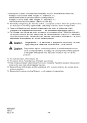
... is kept on . The average current may perform a spin up retry operation. The current measurement is required for power supply. When this drive and in the nominal condition in case of spin up sound will change slightly and the ready timing will also be altered from typical time....3 02.27.01 - 14 - The requirement of this operation occurs, the start up, the drive may have some tolerance after power-on is recommended at Low Power Idle mode. Head position is max. 10 A for possible combustion due to circuit or component failure. Maximum time of data located on to...
... is kept on . The average current may perform a spin up retry operation. The current measurement is required for power supply. When this drive and in the nominal condition in case of spin up sound will change slightly and the ready timing will also be altered from typical time....3 02.27.01 - 14 - The requirement of this operation occurs, the start up, the drive may have some tolerance after power-on is recommended at Low Power Idle mode. Head position is max. 10 A for possible combustion due to circuit or component failure. Maximum time of data located on to...
Specifications
Page 15
...with ESD bag and desiccant. Ambient temperature 55°C 5°C Temperature at a point 10 mm away from the nameplate of the maximum wet bulb 40°C , the drive should be packed in (*5) (with ESD bag and desiccant, maximum wet bulb 29&#...operational ambient temperature cannot be measured at point 10 mm away from the nameplate, a substitution method is 12 months. *3 : In case of the drive. 3.2 Environmental Specifications and Reliability Table 3.2 Environmental Specification and Reliability No. Item Specification DK23CA-30F DK23CA-30/15/75 1 Ambient *1 Operational 5...
...with ESD bag and desiccant. Ambient temperature 55°C 5°C Temperature at a point 10 mm away from the nameplate of the maximum wet bulb 40°C , the drive should be packed in (*5) (with ESD bag and desiccant, maximum wet bulb 29&#...operational ambient temperature cannot be measured at point 10 mm away from the nameplate, a substitution method is 12 months. *3 : In case of the drive. 3.2 Environmental Specifications and Reliability Table 3.2 Environmental Specification and Reliability No. Item Specification DK23CA-30F DK23CA-30/15/75 1 Ambient *1 Operational 5...

Specifications
Page 19
...-Notebook PC(Weight: 1.7kg), the inertia of the chassis around the Z-axis of the gravity center of HDD over 0.020mm should be more than 7 X 10⁻⁴ kg m2. Therefore, the required inertia level has no problem with M3 screws. Take care that the system chassis are flat enough. (d) Consider an appropriate... cooling to keep the temperature of center of HDD top cover less than 100 X 10-4 kg m2. i) M3 (screw engagement of the device is greater than 62°C. (e) The inertia of the chassis around the Z-axis of the ...
...-Notebook PC(Weight: 1.7kg), the inertia of the chassis around the Z-axis of the gravity center of HDD over 0.020mm should be more than 7 X 10⁻⁴ kg m2. Therefore, the required inertia level has no problem with M3 screws. Take care that the system chassis are flat enough. (d) Consider an appropriate... cooling to keep the temperature of center of HDD top cover less than 100 X 10-4 kg m2. i) M3 (screw engagement of the device is greater than 62°C. (e) The inertia of the chassis around the Z-axis of the ...
Specifications
Page 22
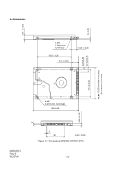
full thread 76.6 ± 0.25 14.0 ± 0.25 10.24 ± 0.25 61.72±0.25 4-M3 3.0mm min. full thread 100±0.45 3.99ʶ0.25 K6602637 Rev.3 02.27.01 2 42 (Unit : mm) Figure 4-4 Dimensions (DK23CA-30F/30/15/75) - 22 - 3ʶ0.25 4.07±0.25 10.14±0.375 69.85ʶ0.25 Drive width at mounting (70.1 Maximum drive width) 9.5 ʶ 0.2 2 4.4 Dimensions 4-M3 3.5mm min.
full thread 76.6 ± 0.25 14.0 ± 0.25 10.24 ± 0.25 61.72±0.25 4-M3 3.0mm min. full thread 100±0.45 3.99ʶ0.25 K6602637 Rev.3 02.27.01 2 42 (Unit : mm) Figure 4-4 Dimensions (DK23CA-30F/30/15/75) - 22 - 3ʶ0.25 4.07±0.25 10.14±0.375 69.85ʶ0.25 Drive width at mounting (70.1 Maximum drive width) 9.5 ʶ 0.2 2 4.4 Dimensions 4-M3 3.5mm min.

Specifications
Page 25
... Transition 1.6 Current of +5V power 1.4 ç (A) 1.2 1.0 0.8 0.6 0.4 0.2 0.0 0 1 2 3 4 5 6 7 Time (sec) Figure 6-1 Power Current Transition Typical Spin-up Current Transition with Retry Retry 1.6 Current of +5V power 1.4 ç (A) 1.2 1.0 0.8 0.6 0.4 0.2 0.0 0 1 2 3 4 5 6 7 8 9 10 11 12 13 14 Time (sec) Figure 6-2 Power Current Transition with retries K6602637 Rev.3 02.27.01 - 25 - 6.0 Interface 6.1 Power Interface Only +5VDC power is...
... Transition 1.6 Current of +5V power 1.4 ç (A) 1.2 1.0 0.8 0.6 0.4 0.2 0.0 0 1 2 3 4 5 6 7 Time (sec) Figure 6-1 Power Current Transition Typical Spin-up Current Transition with Retry Retry 1.6 Current of +5V power 1.4 ç (A) 1.2 1.0 0.8 0.6 0.4 0.2 0.0 0 1 2 3 4 5 6 7 8 9 10 11 12 13 14 Time (sec) Figure 6-2 Power Current Transition with retries K6602637 Rev.3 02.27.01 - 25 - 6.0 Interface 6.1 Power Interface Only +5VDC power is...
Specifications
Page 27
...- 29 INTRQ 31 DA1 33 DA0 35 CS0- 37 DASP- 39 5VDC(Logic) 41 GND(Logic) 43 B JUMPER0 D JUMPER2 F KEY(Removed) 2 GND 4 DD8 6 DD9 8 DD10 10 DD11 12 DD12 14 DD13 16 DD14 18 DD15 20 KEY(Removed) 22 GND 24 GND 26 GND 28 CSEL 30 GND 32 IOCS16- 34...
...- 29 INTRQ 31 DA1 33 DA0 35 CS0- 37 DASP- 39 5VDC(Logic) 41 GND(Logic) 43 B JUMPER0 D JUMPER2 F KEY(Removed) 2 GND 4 DD8 6 DD9 8 DD10 10 DD11 12 DD12 14 DD13 16 DD14 18 DD15 20 KEY(Removed) 22 GND 24 GND 26 GND 28 CSEL 30 GND 32 IOCS16- 34...

Specifications
Page 33
... register. DRV HS3 HS2 HS1 HS0 a) Bits HS3 to HS0 are applied to LBA bits 27 to the description of the Status Register are returned. 6.3.1.10 Command Register The command code is sent to accept any command. If the host reads this register are updated at the completion of a command. Bit...
... register. DRV HS3 HS2 HS1 HS0 a) Bits HS3 to HS0 are applied to LBA bits 27 to the description of the Status Register are returned. 6.3.1.10 Command Register The command code is sent to accept any command. If the host reads this register are updated at the completion of a command. Bit...
Specifications
Page 38
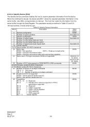
... 8 1 = DMA supported Bit 7 - 0 Vendor Specific Value (HEX.) 045Ah See table 6.6 C837h See table 6.6 See table 6.6 0003h DK23CA-15/ 75: 0400h DK23CA-30F/ 30: 1000h 0004h 8010h 0000h 0B00h K6602637 Rev.3 02.27.01 - 38 - Table 6.5 Identify Device Information Word Description 0 General configuration... Bit 13 1 = Standby timer values as specified in ATA-2 specification supported Bit 12 0 = Reserved Bit 11 1 = IORDY supported Bit 10 1 = IORDY can be zero. The host then reads the information from the device. 6.3.2.3.1 Identify Device [ECh] The Identify Device command enables...
... 8 1 = DMA supported Bit 7 - 0 Vendor Specific Value (HEX.) 045Ah See table 6.6 C837h See table 6.6 See table 6.6 0003h DK23CA-15/ 75: 0400h DK23CA-30F/ 30: 1000h 0004h 8010h 0000h 0B00h K6602637 Rev.3 02.27.01 - 38 - Table 6.5 Identify Device Information Word Description 0 General configuration... Bit 13 1 = Standby timer values as specified in ATA-2 specification supported Bit 12 0 = Reserved Bit 11 1 = IORDY supported Bit 10 1 = IORDY can be zero. The host then reads the information from the device. 6.3.2.3.1 Identify Device [ECh] The Identify Device command enables...
Specifications
Page 40
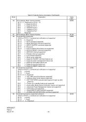
... supported Bit 15 0 = Reserved Bit 14 1 = NOP command supported Bit 13 1 = READ BUFFER command supported Bit 12 1 = WRITE BUFFER command supported Bit 11 0 = Reserved Bit 10 1 = Host Protected Area feature set supported Bit 9 1 = DEVICE RESET command supported Bit 8 1 = SERVICE interrupt supported Bit 7 1 = Release interrupt supported Bit 6 1 = Look-ahead supported Bit 5 1 = Write...
... supported Bit 15 0 = Reserved Bit 14 1 = NOP command supported Bit 13 1 = READ BUFFER command supported Bit 12 1 = WRITE BUFFER command supported Bit 11 0 = Reserved Bit 10 1 = Host Protected Area feature set supported Bit 9 1 = DEVICE RESET command supported Bit 8 1 = SERVICE interrupt supported Bit 7 1 = Release interrupt supported Bit 6 1 = Look-ahead supported Bit 5 1 = Write...
Specifications
Page 41
... supported Bit 15 0 = Reserved Bit 14 1 = NOP command supported Bit 13 1 = READ BUFFER command supported Bit 12 1 = WRITE BUFFER command supported Bit 11 0 = Reserved Bit 10 1 = Host Protected Area feature set supported Bit 9 1 = DEVICE RESET command supported Bit 8 1 = SERVICE interrupt enabled Bit 7 1 = Release interrupt enabled Bit 6 1 = Look-ahead enabled If word...
... supported Bit 15 0 = Reserved Bit 14 1 = NOP command supported Bit 13 1 = READ BUFFER command supported Bit 12 1 = WRITE BUFFER command supported Bit 11 0 = Reserved Bit 10 1 = Host Protected Area feature set supported Bit 9 1 = DEVICE RESET command supported Bit 8 1 = SERVICE interrupt enabled Bit 7 1 = Release interrupt enabled Bit 6 1 = Look-ahead enabled If word...

Specifications
Page 42
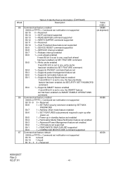
... 15 - 14 0 = Reserved Bit 13 0 = Ultra DMA mode 5 is selected Bit 12 0 = Ultra DMA mode 4 is selected Bit 11 0 = Ultra DMA mode 3 is selected Bit 10 0 = Ultra DMA mode 2 is selected Bit 9 0 = Ultra DMA mode 1 is selected Bit 8 0 = Ultra DMA mode 0 is selected Bit 7 - 6 0 = Reserved Bit 5 0 = Ultra DMA mode 5 and below...
... 15 - 14 0 = Reserved Bit 13 0 = Ultra DMA mode 5 is selected Bit 12 0 = Ultra DMA mode 4 is selected Bit 11 0 = Ultra DMA mode 3 is selected Bit 10 0 = Ultra DMA mode 2 is selected Bit 9 0 = Ultra DMA mode 1 is selected Bit 8 0 = Ultra DMA mode 0 is selected Bit 7 - 6 0 = Reserved Bit 5 0 = Ultra DMA mode 5 and below...

Specifications
Page 43
... 1 = Device 0 passed diagnostic Bit 2 - 1 These bits indicate how Device 0 determined the device number: 00, 11 = Reserved 01 = A jumper was used 10 = the CSEL signal was used Bit 0 1 (fixed) 94-126 Reserved Value (HEX.) XXXXh 0000h K6602637 Rev.3 02.27.01 - 43 - Device 1 sets these... bits to zero. Bit 10 - 9 These bits indicate how Device 1 determined the device number: 00, 11 = Reserved 01 = A jumper was used 10 = the CSEL signal was used Bit 8 1 (fixed) Bit 7 - 0 Device 0 hardware reset result....
... 1 = Device 0 passed diagnostic Bit 2 - 1 These bits indicate how Device 0 determined the device number: 00, 11 = Reserved 01 = A jumper was used 10 = the CSEL signal was used Bit 0 1 (fixed) 94-126 Reserved Value (HEX.) XXXXh 0000h K6602637 Rev.3 02.27.01 - 43 - Device 1 sets these... bits to zero. Bit 10 - 9 These bits indicate how Device 1 determined the device number: 00, 11 = Reserved 01 = A jumper was used 10 = the CSEL signal was used Bit 8 1 (fixed) Bit 7 - 0 Device 0 hardware reset result....
Specifications
Page 44
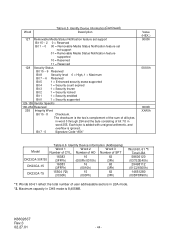
... feature set support Bit 15 - 2 0 = Reserved Bit 1 - 0 00 = Removable Media Status Notification feature set not support 01 = Removable Media Status Notification feature supported 10 = Reserved 11 = Reserved 128 Security Status Bit 15 - 9 Reserved Bit 8 Security level 0 = High, 1 = Maximum Bit 7 - 6 Reserved Bit 5 1 =... 3 Number of user addressable sectors in word 255. Number of HD Number of SPT DK23CA-30F/30 16383 (3FFFh) 16 (000Fh/0010h) 63 (3Fh) DK23CA-15 16383 (3FFFh) 16 (0010h) 63 (3Fh) DK23CA-75 15504 (*2) (3C90h) 15 (000Fh) 63 (3Fh) Word 60Ŋ61 ...
... feature set support Bit 15 - 2 0 = Reserved Bit 1 - 0 00 = Removable Media Status Notification feature set not support 01 = Removable Media Status Notification feature supported 10 = Reserved 11 = Reserved 128 Security Status Bit 15 - 9 Reserved Bit 8 Security level 0 = High, 1 = Maximum Bit 7 - 6 Reserved Bit 5 1 =... 3 Number of user addressable sectors in word 255. Number of HD Number of SPT DK23CA-30F/30 16383 (3FFFh) 16 (000Fh/0010h) 63 (3Fh) DK23CA-15 16383 (3FFFh) 16 (0010h) 63 (3Fh) DK23CA-75 15504 (*2) (3C90h) 15 (000Fh) 63 (3Fh) Word 60Ŋ61 ...
Specifications
Page 48
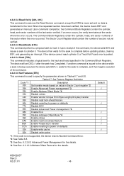
...; Ö *1: If the code is not supported, the device returns Aborted Command Error. *2: See Table 6.8. *3: See Sec. 6.3.2.6.2 Advanced Power Management for the details. *4: See Sec. 6.3.10.2 Address Offset Feature for the seek to the host. The device then waits for the details. 6.3.2.5.2 Read Verify [40h, 41h] This command is same as...
...; Ö *1: If the code is not supported, the device returns Aborted Command Error. *2: See Table 6.8. *3: See Sec. 6.3.2.6.2 Advanced Power Management for the details. *4: See Sec. 6.3.10.2 Address Offset Feature for the seek to the host. The device then waits for the details. 6.3.2.5.2 Read Verify [40h, 41h] This command is same as...