Owners Manual
Page 2
...users read and follow all instructions and cautions indicated throughout this manual were thoroughly considered, but also be careful for safe use this manual Followings are not followed. The indication and meaning are as the following headline, which may cause damage to...but unexpected situations can occur. Safety Instructions Items of indicating Caution : - Keep this manual with care to use this manual. Maximum Power off Interval - Please read the caution for drive usage in this product safely This manual is for HDD Installation - Handling Page 4 Sec. 1.2, Page 9...
...users read and follow all instructions and cautions indicated throughout this manual were thoroughly considered, but also be careful for safe use this manual Followings are not followed. The indication and meaning are as the following headline, which may cause damage to...but unexpected situations can occur. Safety Instructions Items of indicating Caution : - Keep this manual with care to use this manual. Maximum Power off Interval - Please read the caution for drive usage in this product safely This manual is for HDD Installation - Handling Page 4 Sec. 1.2, Page 9...
Owners Manual
Page 3
...improvement for the electro-magnetic field regulations. 1) Disturbance of operations of other products or equipment. IEC60950 A4: 1996 - In general, Hitachi shall not be responsible for a complete statement of warranty rights, remedies and limitation of liability. K6610007 Rev.5 02.14.'03 -...Please see your sales contract for product damages caused by anyone else. Only Hitachi trained persons should consider the safety of the system with its sales contact. To use this product safely (Continued) z Environmental circumstance Although this product partially scatters ...
...improvement for the electro-magnetic field regulations. 1) Disturbance of operations of other products or equipment. IEC60950 A4: 1996 - In general, Hitachi shall not be responsible for a complete statement of warranty rights, remedies and limitation of liability. K6610007 Rev.5 02.14.'03 -...Please see your sales contract for product damages caused by anyone else. Only Hitachi trained persons should consider the safety of the system with its sales contact. To use this product safely (Continued) z Environmental circumstance Although this product partially scatters ...
Owners Manual
Page 4
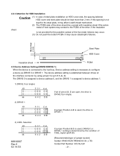
...side of screws and the torque recommended in permanent damage to the drive and/or loss of personal injury. 2. To fix the drive, use in permanent damage to the connector insertion or jumper setting can damage the drive. If non-recommended size screws and torque are not kept within.... Safety Instructions Caution 1. Dropping of Metal Head Disk Assembly (HDA) may cause catastrophic failures. Since the drive uses glass media for use the size of the drive should protect the drive from ESD during Power Off only. 9. The product is not authorized for the disk platter, opening of ...
...side of screws and the torque recommended in permanent damage to the drive and/or loss of personal injury. 2. To fix the drive, use in permanent damage to the connector insertion or jumper setting can damage the drive. If non-recommended size screws and torque are not kept within.... Safety Instructions Caution 1. Dropping of Metal Head Disk Assembly (HDA) may cause catastrophic failures. Since the drive uses glass media for use the size of the drive should protect the drive from ESD during Power Off only. 9. The product is not authorized for the disk platter, opening of ...
Owners Manual
Page 5
... a box. 20. NOTE TO USERS While every effort has been made to ensure that the information provided herein is packed in the event of such revisions or changes. Use original packages (50 units' package) during drive transportation to unexpected or accidental power loss during handling or drive failure. K6610007 Rev.5 02.14.'03 - 5 - Hitachi does...
... a box. 20. NOTE TO USERS While every effort has been made to ensure that the information provided herein is packed in the event of such revisions or changes. Use original packages (50 units' package) during drive transportation to unexpected or accidental power loss during handling or drive failure. K6610007 Rev.5 02.14.'03 - 5 - Hitachi does...
Owners Manual
Page 6
...use this product safely 1. 0 General 1.1 General 1.2 General Caution 2.0 Components 3.0 Specification Summary 3.1 Principal Specifications 3.2 Environmental Specifications and Reliability 3.3 Drive Usage Condition Specifications 3.4 Load/Unload Specifications 3.4.1 Normal Load/Unload 3.4.2 Emergency Unload 3.4.3 Required Power Off Sequence 4.0 Installation 4.1 Installation Direction 4.2 Mounting HDD 4.2.1 Mounting HDD with Screws 4.2.2 Single HDD Test Condition 4.2.3 Attention for HDD Installation 4.3 Drive Address Setting(DRIVE 0/DRIVE... 18 18 19 19 20 21 21 22 23 ...
...use this product safely 1. 0 General 1.1 General 1.2 General Caution 2.0 Components 3.0 Specification Summary 3.1 Principal Specifications 3.2 Environmental Specifications and Reliability 3.3 Drive Usage Condition Specifications 3.4 Load/Unload Specifications 3.4.1 Normal Load/Unload 3.4.2 Emergency Unload 3.4.3 Required Power Off Sequence 4.0 Installation 4.1 Installation Direction 4.2 Mounting HDD 4.2.1 Mounting HDD with Screws 4.2.2 Single HDD Test Condition 4.2.3 Attention for HDD Installation 4.3 Drive Address Setting(DRIVE 0/DRIVE... 18 18 19 19 20 21 21 22 23 ...
Owners Manual
Page 16
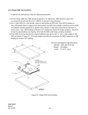
.... The grounding current should be less than 20% of the drive. Grounding noise should be taken in Table 3.2 -Mounting : Mount with ISO 7779. Seek rate for the drive can be measured between two of the magnet... in Table 3.2 -Power Requirement : Within DC power requirement specifications given in Table 3.1 "Principal Specifications" -Drive Grounding : Drive frame should be measured through 50 ohm resistor. -External Magnetic Field : Within specifications given in accordance with ...,000 times. The grounding noise should be used to system ground with A-weighted.
.... The grounding current should be less than 20% of the drive. Grounding noise should be taken in Table 3.2 -Mounting : Mount with ISO 7779. Seek rate for the drive can be measured between two of the magnet... in Table 3.2 -Power Requirement : Within DC power requirement specifications given in Table 3.1 "Principal Specifications" -Drive Grounding : Drive frame should be measured through 50 ohm resistor. -External Magnetic Field : Within specifications given in accordance with ...,000 times. The grounding noise should be used to system ground with A-weighted.
Owners Manual
Page 19
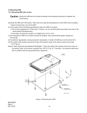
..., secure the HDD. (b) Use screws with the following instruction to the HDD when mounting. i) M3 (screw engagement of HDD over 0.020mm should be more than 100 X 10-4 kg m2. ...-4 kg m2. Take care not to add any distorting force to optimize the performance. (a) Mount the HDD with the general electronic equipment. However, do not use both bottom and side screw hole at the same position simultaneously.) ii) The torque for fixing the screws is 3±0.5kgcm(2.6±0.4 lb. HDD K6610007...
..., secure the HDD. (b) Use screws with the following instruction to the HDD when mounting. i) M3 (screw engagement of HDD over 0.020mm should be more than 100 X 10-4 kg m2. ...-4 kg m2. Take care not to add any distorting force to optimize the performance. (a) Mount the HDD with the general electronic equipment. However, do not use both bottom and side screw hole at the same position simultaneously.) ii) The torque for fixing the screws is 3±0.5kgcm(2.6±0.4 lb. HDD K6610007...
Owners Manual
Page 20
...of I =7.3X10⁻⁴ kg m2 ) HDD X Axis Direction K6610007 Rev.5 02.14.'03 ABS-sheet (t = 5mm) Figure 4-3 Single HDD Test Condition - 20 - 4.2.2 Single HDD Test Condition To optimize the performance, keep the following instructions. 1) For the Single HDD test, HDD should be fixed by the required ... such as specified below. The HDD should be place with Insulation sheet (m=0.66kg, I /F cabling. (70) (13) Use the body weight as HDD self-vibration at HDD test. The body weight is placed on a soft sponge sheet or hard surface at seek operations or spindle motor rotation.
...of I =7.3X10⁻⁴ kg m2 ) HDD X Axis Direction K6610007 Rev.5 02.14.'03 ABS-sheet (t = 5mm) Figure 4-3 Single HDD Test Condition - 20 - 4.2.2 Single HDD Test Condition To optimize the performance, keep the following instructions. 1) For the Single HDD test, HDD should be fixed by the required ... such as specified below. The HDD should be place with Insulation sheet (m=0.66kg, I /F cabling. (70) (13) Use the body weight as HDD self-vibration at HDD test. The body weight is placed on a soft sponge sheet or hard surface at seek operations or spindle motor rotation.
Owners Manual
Page 21
... of pins A,B, D are open, the drive is DRIVE 0(or single). 2) DRIVE 1 43 5 31 O O O O O O O O 44 642 CA O O O O DB If jumper Position A-B is used, the drive is DRIVE 1. 3) CSEL Selection 43 5 31 O O O O O O O O 44 642 CA O O O O DB K6610007 Rev.5 02.14.'03 If jumper Position B-D is used, DRIVE 0 or DRIVE 1 setting is determined by using jumper 0-2 (pin # A, B, D) The DRIVE 0 is assigned to device address...
... of pins A,B, D are open, the drive is DRIVE 0(or single). 2) DRIVE 1 43 5 31 O O O O O O O O 44 642 CA O O O O DB If jumper Position A-B is used, the drive is DRIVE 1. 3) CSEL Selection 43 5 31 O O O O O O O O 44 642 CA O O O O DB K6610007 Rev.5 02.14.'03 If jumper Position B-D is used, DRIVE 0 or DRIVE 1 setting is determined by using jumper 0-2 (pin # A, B, D) The DRIVE 0 is assigned to device address...
Owners Manual
Page 23
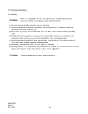
... material separating them. (4) Indicate which side is packed in an ESD protective bag with desiccant. (2) Use the original Hitachi cardboard box and the cushioning materials or equivalent cushioning structures to surround the above bag. (3) Never stack or package drives next to prevent humidity and handling damage and contamination. (1) Pack the device in a box.
... material separating them. (4) Indicate which side is packed in an ESD protective bag with desiccant. (2) Use the original Hitachi cardboard box and the cushioning materials or equivalent cushioning structures to surround the above bag. (3) Never stack or package drives next to prevent humidity and handling damage and contamination. (1) Pack the device in a box.
Owners Manual
Page 28
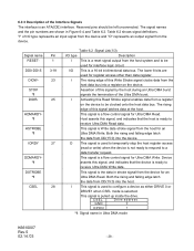
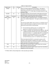
... from the device for an Ultra DMA Read. This signal is a flow control signal for Ultra DMA Write. This signal is pulled up inside the drive. CSEL GND D rive address 0 OPEN 1 *1: Signal name in Figure 6-4 and Table 6.2. The lower 8 bits are shown in Ultra DMA mode K6610007 ...signal from the host system and to be left unconnected. I This signal is used to temporarily stop the host register access (read or write) when the device is ready to configure a device as either DRIVE 0 or DRIVE1 when CSEL mode is Write data strobe signal from the host data...
... from the device for an Ultra DMA Read. This signal is a flow control signal for Ultra DMA Write. This signal is pulled up inside the drive. CSEL GND D rive address 0 OPEN 1 *1: Signal name in Figure 6-4 and Table 6.2. The lower 8 bits are shown in Ultra DMA mode K6610007 ...signal from the host system and to be left unconnected. I This signal is used to temporarily stop the host register access (read or write) when the device is ready to configure a device as either DRIVE 0 or DRIVE1 when CSEL mode is Write data strobe signal from the host data...
Owners Manual
Page 29
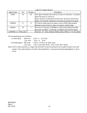
... device compliant with ATA-3 or subsequent standards. If the host detects that this signal should issue IDENTIFY DEVICE or IDENTIFY PACKET DEVICE and use the returned data to Device 0 that it has completed diagnostics. is connected to detect the presence or absence of an 80-conductor cable...devices on or hardware reset sequence. This signal is a register address signal from the host system. 38 I This device chip selection signal is used to select the Command Block Registers from the host system. This signal indicates to the host that Device 1 is compliant with ATA-3 or ...
... device compliant with ATA-3 or subsequent standards. If the host detects that this signal should issue IDENTIFY DEVICE or IDENTIFY PACKET DEVICE and use the returned data to Device 0 that it has completed diagnostics. is connected to detect the presence or absence of an 80-conductor cable...devices on or hardware reset sequence. This signal is a register address signal from the host system. 38 I This device chip selection signal is used to select the Command Block Registers from the host system. This signal indicates to the host that Device 1 is compliant with ATA-3 or ...
Owners Manual
Page 30
...=2mA), +0.5V or less (IOL=12mA) Note) The I - See Sec. 4.3 " Drive Address Setting (Drive 0/Drive 1)" for DMA data transfers between host and device, when it is available shall use this specification, it may cause factional degradations or some errors. K6610007 Rev.5 02.14.'03 -... 30 - DMARQ DMACKJUMPER0,1,2 Pin 39 21 29 PIN-A,B,D I/O type I/O O I /F cable should be no longer than 50cm(20...
...=2mA), +0.5V or less (IOL=12mA) Note) The I - See Sec. 4.3 " Drive Address Setting (Drive 0/Drive 1)" for DMA data transfers between host and device, when it is available shall use this specification, it may cause factional degradations or some errors. K6610007 Rev.5 02.14.'03 -... 30 - DMARQ DMACKJUMPER0,1,2 Pin 39 21 29 PIN-A,B,D I/O type I/O O I /F cable should be no longer than 50cm(20...
Owners Manual
Page 31
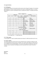
... Number 0 1 1 0 0 Cyl Low Cyl Low 0 1 1 0 1 Cyl High Cyl High 0 1 1 1 0 Device/Head Device/Head 0 1 1 1 1 Status Command Control Block Registers 1 0 1 1 0 Alt. The contents of this register are used for transferring data blocks between the host system and the device is set in Table 6.3. 6.3 Logical Interface 6.3.1 I/O Registers Communication between the HDD's data buffer and...
... Number 0 1 1 0 0 Cyl Low Cyl Low 0 1 1 0 1 Cyl High Cyl High 0 1 1 1 0 Device/Head Device/Head 0 1 1 1 1 Status Command Control Block Registers 1 0 1 1 0 Alt. The contents of this register are used for transferring data blocks between the host system and the device is set in Table 6.3. 6.3 Logical Interface 6.3.1 I/O Registers Communication between the HDD's data buffer and...
Owners Manual
Page 32
... lower 8 bits of the requested sector is not found. d) IDNF (ID Not Found): This bit indicates that an uncorrectable error has occurred. This bit is used for any disk data access. e) UNC(Uncorrectable Data Error): This bit indicates that an ID field of the starting sector number for Multiword DMA transfers...
... lower 8 bits of the requested sector is not found. d) IDNF (ID Not Found): This bit indicates that an uncorrectable error has occurred. This bit is used for any disk data access. e) UNC(Uncorrectable Data Error): This bit indicates that an ID field of the starting sector number for Multiword DMA transfers...
Owners Manual
Page 43
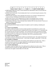
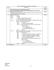
...11 1 = Device 1 asserted PDIAG- Bit 10 - 9 These bits indicate how Device 1 determined the device number: 00, 11 = Reserved 01 = A jumper was used 10 = the CSEL signal was last changed. 93 Hardware reset result Bit 15 0 (fixed) Bit 14 1 (fixed) Bit 13 Bit 12 - 8 1 = ... Management level settings. 92 Master password revision code Word 92 contains the value of the Master password revision code set when the Master Password was used Bit 8 1 (fixed) Bit 7 - 0 Device 0 hardware reset result. Bit 4 1 = Device 0 detected the assertion of PDIAG0 Bit 3 1 = Device 0 passed diagnostic...
...11 1 = Device 1 asserted PDIAG- Bit 10 - 9 These bits indicate how Device 1 determined the device number: 00, 11 = Reserved 01 = A jumper was used 10 = the CSEL signal was last changed. 93 Hardware reset result Bit 15 0 (fixed) Bit 14 1 (fixed) Bit 13 Bit 12 - 8 1 = ... Management level settings. 92 Master password revision code Word 92 contains the value of the Master password revision code set when the Master Password was used Bit 8 1 (fixed) Bit 7 - 0 Device 0 hardware reset result. Bit 4 1 = Device 0 detected the assertion of PDIAG0 Bit 3 1 = Device 0 passed diagnostic...
Owners Manual
Page 47
...generated when DRQ is filled with "0" DD15-8 contains the sector number, and DD7-0 contains one of the descriptor values defined as good This command is used for the host fill the sector buffer. K6610007 Rev.5 02.14.'03 - 47 - Code Formatting method 00h Formats a sector as follows. The ... the format table data remains below 512 bytes after words of the last sector are entered, the buffer should be for validity by this command uses are invalid, no error will be transferred. The sector count and head values are not checked for n sectors, where n = residue of {...
...generated when DRQ is filled with "0" DD15-8 contains the sector number, and DD7-0 contains one of the descriptor values defined as good This command is used for the host fill the sector buffer. K6610007 Rev.5 02.14.'03 - 47 - Code Formatting method 00h Formats a sector as follows. The ... the format table data remains below 512 bytes after words of the last sector are entered, the buffer should be for validity by this command uses are invalid, no error will be transferred. The sector count and head values are not checked for n sectors, where n = residue of {...
Owners Manual
Page 48
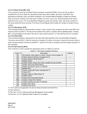
... being executed, the device sets BSY=1, waits for the seek to complete, and then begins execution of the command. 6.3.2.5.5 Set Features [EFh] This command is used to specify the parameters shown in Sector Count register *2 Enable Advanced Power management *3 Enable Address Offset Mode *4 Disable retries Enable Vendor Unique ECC Byte Length...
... being executed, the device sets BSY=1, waits for the seek to complete, and then begins execution of the command. 6.3.2.5.5 Set Features [EFh] This command is used to specify the parameters shown in Sector Count register *2 Enable Advanced Power management *3 Enable Address Offset Mode *4 Disable retries Enable Vendor Unique ECC Byte Length...
Owners Manual
Page 52
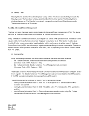
... to FEh, the performance is always set the mode and reset the mode. - The Standby timer is enabled. - Using Set Feature command and Sector Count register can be set to FEh. (1) Command Set Using the following command, the APM control can select the power saving control pattern by Set Feature command and... by Identify Device command as follows: - The device automatically moves to the performance level and the power consumption level. The Sector count value is changeable using Idle and Standby commands.
... to FEh, the performance is always set the mode and reset the mode. - The Standby timer is enabled. - Using Set Feature command and Sector Count register can be set to FEh. (1) Command Set Using the following command, the APM control can select the power saving control pattern by Set Feature command and... by Identify Device command as follows: - The device automatically moves to the performance level and the power consumption level. The Sector count value is changeable using Idle and Standby commands.
Owners Manual
Page 55
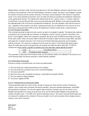
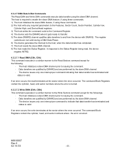
... per command to indicate that data transfer has terminated and status is valid. The host is required to enable the slave-DMA feature, if using these commands. 2) The host write any required parameters to the Features, Sector Count, Sector Number, Cylinder low, Cylinder High, and Device/Head... with DMARQ. 6.3.2.7 DMA Data In/Out Commands The Read DMA and Write DMA commands execute data transfer using these commands. 1) The host initializes the slave-DMA feature, if using the slave-DMA channel. The host initializes a slave-DMA channel prior to the Read Sectors command except ...
... per command to indicate that data transfer has terminated and status is valid. The host is required to enable the slave-DMA feature, if using these commands. 2) The host write any required parameters to the Features, Sector Count, Sector Number, Cylinder low, Cylinder High, and Device/Head... with DMARQ. 6.3.2.7 DMA Data In/Out Commands The Read DMA and Write DMA commands execute data transfer using these commands. 1) The host initializes the slave-DMA feature, if using the slave-DMA channel. The host initializes a slave-DMA channel prior to the Read Sectors command except ...


