
Owners Manual
Page 4
Handle with care. 4. Observe Clause 3.3 "Drive Usage Condition Specifications". Referring to this manual prior to the connector insertion or jumper setting can damage the drive. on PCBA), it may cause bodily injury. To fix the drive, use in life support devices or systems or other objects. It may cause catastrophic failures. If this manual. Do not hit the interface connector pins against other applications that pose a significant...
Handle with care. 4. Observe Clause 3.3 "Drive Usage Condition Specifications". Referring to this manual prior to the connector insertion or jumper setting can damage the drive. on PCBA), it may cause bodily injury. To fix the drive, use in life support devices or systems or other objects. It may cause catastrophic failures. If this manual. Do not hit the interface connector pins against other applications that pose a significant...
Owners Manual
Page 9
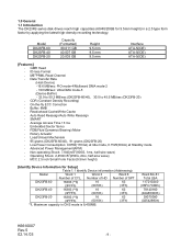
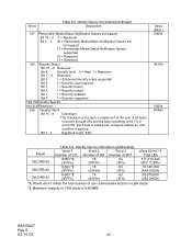
... Read Channel - Read-ahead Cache/Write Cache - SMART - CDR (Constant Density Recording) - Auto Read Reassign/Auto Write Reassign - Number of HD Number of CYL. ID-less Format - Non-operating Shock 7,840m/S2(800G, 1ms, half-sine wave) - FDB(Fluid Dynamics Bearing) Motor - Model DK23FB-60 DK23FB-40 DK23FB-20 Capacity (Formatted) 60.011 GB 40.007 GB 20.003 GB Height 9.5 mm 9.5 mm 9.5 mm Interface ATA-5(IDE) ATA-5(IDE) ATA-5(IDE) [Features] - Data Transfer Rate (Host-Device) -16.6 MB/sec: PIO mode...
... Read Channel - Read-ahead Cache/Write Cache - SMART - CDR (Constant Density Recording) - Auto Read Reassign/Auto Write Reassign - Number of HD Number of CYL. ID-less Format - Non-operating Shock 7,840m/S2(800G, 1ms, half-sine wave) - FDB(Fluid Dynamics Bearing) Motor - Model DK23FB-60 DK23FB-40 DK23FB-20 Capacity (Formatted) 60.011 GB 40.007 GB 20.003 GB Height 9.5 mm 9.5 mm 9.5 mm Interface ATA-5(IDE) ATA-5(IDE) ATA-5(IDE) [Features] - Data Transfer Rate (Host-Device) -16.6 MB/sec: PIO mode...
Owners Manual
Page 16
... unloading operation of POH Read operations) -Motor Start/Stop Count : Max. 300,000 times. Seek rate = 0.4/(average access time + average latency) = 0.4/(average access time + 60/RPM/2) *5 : Caution Data reliability is stopped during Power off count. -Environment : Within environmental specifications given in Table 3.2 -Power Requirement : Within DC power requirement specifications given in Table 3.1 "Principal Specifications" -Drive Grounding : Drive frame should be less than 50 mAp-p (Frequency Range: less than 20% of the magnetic heads...
... unloading operation of POH Read operations) -Motor Start/Stop Count : Max. 300,000 times. Seek rate = 0.4/(average access time + average latency) = 0.4/(average access time + 60/RPM/2) *5 : Caution Data reliability is stopped during Power off count. -Environment : Within environmental specifications given in Table 3.2 -Power Requirement : Within DC power requirement specifications given in Table 3.1 "Principal Specifications" -Drive Grounding : Drive frame should be less than 50 mAp-p (Frequency Range: less than 20% of the magnetic heads...
Owners Manual
Page 17
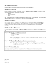
... time does not include an emergency unload as Soft Reset, Flush Cache command or Check Power Mode command does not unload the heads. [Sequence #2]: Check the Status Register, and wait the command complete. The normal unload operation is performed by the sequence #1 command, and the command completion normally takes about 1sec. Sleep Also, the normal unload is automatically performed by control software, during HDD life. Considering the error retries, BIOS...
... time does not include an emergency unload as Soft Reset, Flush Cache command or Check Power Mode command does not unload the heads. [Sequence #2]: Check the Status Register, and wait the command complete. The normal unload operation is performed by the sequence #1 command, and the command completion normally takes about 1sec. Sleep Also, the normal unload is automatically performed by control software, during HDD life. Considering the error retries, BIOS...
Owners Manual
Page 35
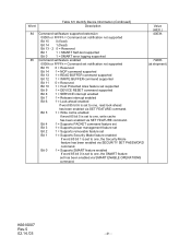
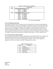
...V V Write Commands Write Buffer PO 2 E8h D Write Sectors PO 2 30h, 31h V V V V Write Long PO 2 32h, 33h V V V V Write Multiple PO 3 C5h V V V V Write DMA DM 3 CAh,CBh V V V V Format Track PO 2 50h V V V Flush Cache ND 1 E7h D Seek Commands Recalibrate ND 1 1Xh D Seek ND 1 7Xh V V V Mode Set/Check, Diagnostic Execute Device Diagnostic ND 1 90h D Initialize Device Parameters ND 1 91h V V Identify Device PI 1 ECh D Set Features ND 1 EFh V D Set Multiple Mode ND 1 C6h V D Power Control Check Power Mode ND...
...V V Write Commands Write Buffer PO 2 E8h D Write Sectors PO 2 30h, 31h V V V V Write Long PO 2 32h, 33h V V V V Write Multiple PO 3 C5h V V V V Write DMA DM 3 CAh,CBh V V V V Format Track PO 2 50h V V V Flush Cache ND 1 E7h D Seek Commands Recalibrate ND 1 1Xh D Seek ND 1 7Xh V V V Mode Set/Check, Diagnostic Execute Device Diagnostic ND 1 90h D Initialize Device Parameters ND 1 91h V V Identify Device PI 1 ECh D Set Features ND 1 EFh V D Set Multiple Mode ND 1 C6h V D Power Control Check Power Mode ND...
Owners Manual
Page 41
... 1 1 = SMART Self-test supported Bit 0 1 = SMART error logging supported 85 Command set/feature enabled 0000h or FFFFh = Command set notification not supported Bit 15 0 = Reserved Bit 14 1 = NOP command supported Bit 13 1 = READ BUFFER command supported Bit 12 1 = WRITE BUFFER command supported Bit 11 0 = Reserved Bit 10 1 = Host Protected Area feature set supported Bit 9 1 = DEVICE RESET command supported Bit 8 1 = SERVICE interrupt enabled Bit 7 1 = Release interrupt enabled Bit 6 1 = Look-ahead enabled If word 85 bit 6 is set to one , write cache has been enabled via SET...
... 1 1 = SMART Self-test supported Bit 0 1 = SMART error logging supported 85 Command set/feature enabled 0000h or FFFFh = Command set notification not supported Bit 15 0 = Reserved Bit 14 1 = NOP command supported Bit 13 1 = READ BUFFER command supported Bit 12 1 = WRITE BUFFER command supported Bit 11 0 = Reserved Bit 10 1 = Host Protected Area feature set supported Bit 9 1 = DEVICE RESET command supported Bit 8 1 = SERVICE interrupt enabled Bit 7 1 = Release interrupt enabled Bit 6 1 = Look-ahead enabled If word 85 bit 6 is set to one , write cache has been enabled via SET...
Owners Manual
Page 44
... Status Notification feature set not support 01 = Removable Media Status Notification feature supported 10 = Reserved 11 = Reserved 128 Security Status Bit 15 - 9 Reserved Bit 8 Security level 0 = High, 1 = Maximum Bit 7 - 6 Reserved Bit 5 1 = Enhanced security erase supported Bit 4 1 = Security count expired Bit 3 1 = Security frozen Bit 2 1 = Security locked Bit 1 1 = Security enabled Bit 0 1 = Security supported 129-159 Vendor Specific 160-254 Reserved 255 Integrity Word Bit 15 - 8 Checksum. Maximum capacity in LBA mode. *2. The checksum...
... Status Notification feature set not support 01 = Removable Media Status Notification feature supported 10 = Reserved 11 = Reserved 128 Security Status Bit 15 - 9 Reserved Bit 8 Security level 0 = High, 1 = Maximum Bit 7 - 6 Reserved Bit 5 1 = Enhanced security erase supported Bit 4 1 = Security count expired Bit 3 1 = Security frozen Bit 2 1 = Security locked Bit 1 1 = Security enabled Bit 0 1 = Security supported 129-159 Vendor Specific 160-254 Reserved 255 Integrity Word Bit 15 - 8 Checksum. Maximum capacity in LBA mode. *2. The checksum...
Owners Manual
Page 45
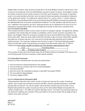
... command is set prior to data transfer regardless of the presence or absence of the last sector read. The Set Multiple Mode command, which the device searches for the target sector. The host then reads up the sector buffer for n sectors, where n = residue of corrupted data, if any. The Command Block Registers contain the cylinder, head, and sector numbers where the error occurred. 6.3.2.3.4 Read Long [22h, 23h] The Read Long command performs similarly to the Read Sectors command...
... command is set prior to data transfer regardless of the presence or absence of the last sector read. The Set Multiple Mode command, which the device searches for the target sector. The host then reads up the sector buffer for n sectors, where n = residue of corrupted data, if any. The Command Block Registers contain the cylinder, head, and sector numbers where the error occurred. 6.3.2.3.4 Read Long [22h, 23h] The Read Long command performs similarly to the Read Sectors command...
Owners Manual
Page 46
... Features, Sector Count, Sector Number, Cylinder Low, Cylinder High, and Device/Head Registers. 2) The host writes the command code to the Command Register. 3) The device sets the DRQ when it gets ready to accept the first sector(block) of data. 4) The host writes one sector, writing terminates at the start of the data block, not on every sector, but with retries disabled, an ID Not Found Error is similar to the Write Sectors command, except...
... Features, Sector Count, Sector Number, Cylinder Low, Cylinder High, and Device/Head Registers. 2) The host writes the command code to the Command Register. 3) The device sets the DRQ when it gets ready to accept the first sector(block) of data. 4) The host writes one sector, writing terminates at the start of the data block, not on every sector, but with retries disabled, an ID Not Found Error is similar to the Write Sectors command, except...
Owners Manual
Page 47
... attempted disk write of the position in the Sector Count Register. The sector count and head values are entered, the buffer should be filled with the sector in the Physical mode, the device executes a vendor specific operation. 6.3.2.5 Non-Data Commands Execution of the last sector are not checked for selecting a device. If the number of requested sector is not in error, regardless of the block or partial block transferred...
... attempted disk write of the position in the Sector Count Register. The sector count and head values are entered, the buffer should be filled with the sector in the Physical mode, the device executes a vendor specific operation. 6.3.2.5 Non-Data Commands Execution of the last sector are not checked for selecting a device. If the number of requested sector is not in error, regardless of the block or partial block transferred...
Owners Manual
Page 48
... begins execution of the command, the device sets BSY and issues a seek to power on defaults Disable ECC Disable Advanced Power management *3 Enable ECC Disable Address Offset Mode *4 Enable retries Enable read look -ahead feature Enable 4 bytes ECC transfer Enable reverting to cylinder 0. When the requested sectors have been verified, the device clears BSY and generates an interrupt. Upon command completion, the Command Block Registers contain the cylinder, head, and sector numbers of the sector where the error occurred.
... begins execution of the command, the device sets BSY and issues a seek to power on defaults Disable ECC Disable Advanced Power management *3 Enable ECC Disable Address Offset Mode *4 Enable retries Enable read look -ahead feature Enable 4 bytes ECC transfer Enable reverting to cylinder 0. When the requested sectors have been verified, the device clears BSY and generates an interrupt. Upon command completion, the Command Block Registers contain the cylinder, head, and sector numbers of the sector where the error occurred.
Owners Manual
Page 49
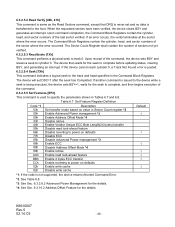
... the default mode at power on or after a hardware reset. 6.3.2.5.7 Execute device diagnostic [90h] This command allows the device to perform Read Multiple and Write Multiple operations. Block sizes of 2, 4, 8, and 16 sectors are connected in the Error register, clears BSY, and generates an interrupt. When the device receives this command is disabled. When DRV0 and DRV1 are supported. Table 6.9 Diagnostic Codes Code Contents 01 No Error 02 Controller error 03 Sector buffer error 05 CPU error 8X DRV1 error...
... the default mode at power on or after a hardware reset. 6.3.2.5.7 Execute device diagnostic [90h] This command allows the device to perform Read Multiple and Write Multiple operations. Block sizes of 2, 4, 8, and 16 sectors are connected in the Error register, clears BSY, and generates an interrupt. When the device receives this command is disabled. When DRV0 and DRV1 are supported. Table 6.9 Diagnostic Codes Code Contents 01 No Error 02 Controller error 03 Sector buffer error 05 CPU error 8X DRV1 error...
Owners Manual
Page 57
...data will be reset to the existing SMART Read Logging Sectors. A host can deliver the error information using the SMART READ LOG SECTOR command. The system manufacturer or the applications shall enable SMART. 6.3.2.8.5 SMART Enable Operations [B0h, Sub D8h] Task File Registers Command Cylinder High Cylinder Low Device/Head Sector Number Sector Count Features DRV : Device selection bit K6610007 Rev.5 02.14.'03 7 6 5 4 3 2 1 0 B0h C2h 4Fh - X - The errors that have generated error conditions. If a device receives a firmware modification, all times the device is powered on device...
...data will be reset to the existing SMART Read Logging Sectors. A host can deliver the error information using the SMART READ LOG SECTOR command. The system manufacturer or the applications shall enable SMART. 6.3.2.8.5 SMART Enable Operations [B0h, Sub D8h] Task File Registers Command Cylinder High Cylinder Low Device/Head Sector Number Sector Count Features DRV : Device selection bit K6610007 Rev.5 02.14.'03 7 6 5 4 3 2 1 0 B0h C2h 4Fh - X - The errors that have generated error conditions. If a device receives a firmware modification, all times the device is powered on device...
Owners Manual
Page 68
... comprehensive SMART error log data structures include UNC errors, IDNF errors for this field is viewed as command codes not supported by the device during the life of the sectors that have been reported by the device or requests with zeros. The sixth error after that creates an error log data structure that replaces the first error log data structure in sector zero. The maximum size of the error log data...
... comprehensive SMART error log data structures include UNC errors, IDNF errors for this field is viewed as command codes not supported by the device during the life of the sectors that have been reported by the device or requests with zeros. The sixth error after that creates an error log data structure that replaces the first error log data structure in sector zero. The maximum size of the error log data...
Owners Manual
Page 75
... password supplied with the command shall be saved as the new user password. The lock function shall be enabled from the next power-on or hardware reset. Master password revision code set is returned in the device but shall not enable or disable the lock function. The initial factory shipped value of data from the host. The following table defines the interaction of information. The device shall then be unlocked by only the user password...
... password supplied with the command shall be saved as the new user password. The lock function shall be enabled from the next power-on or hardware reset. Master password revision code set is returned in the device but shall not enable or disable the lock function. The initial factory shipped value of data from the host. The following table defines the interaction of information. The device shall then be unlocked by only the user password...
Owners Manual
Page 77
... time of this sector of data from the host. If the device receives a Security Erase Unit command without an immediately prior Security Erase Prepare command, the device aborts the Security Erase unit command This command disables the device lock function, however, the master password is still stored internally within the device and may be reactivated later when a new user password is in Frozen mode. 6.3.2.9.8 Security Erase Unit [F4h] This command requests a transfer of a single sector of information. Device returns Aborted command error if the device is set. 6.3.2.9.7 Security...
... time of this sector of data from the host. If the device receives a Security Erase Unit command without an immediately prior Security Erase Prepare command, the device aborts the Security Erase unit command This command disables the device lock function, however, the master password is still stored internally within the device and may be reactivated later when a new user password is in Frozen mode. 6.3.2.9.8 Security Erase Unit [F4h] This command requests a transfer of a single sector of information. Device returns Aborted command error if the device is set. 6.3.2.9.7 Security...
Owners Manual
Page 79
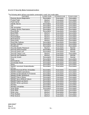
...Sectors Aborted Executable Read Verify Aborted Executable Read Max Address Executable Executable Set Max Address Executable Executable Recalibrate Executable Executable Security Disable Password Aborted Executable Security Erase Prepare Executable Executable Security Erase Unit Executable Executable Security Freeze Lock Aborted Executable Security Set Password Aborted Executable Security Unlock Executable Executable Seek Executable Executable Set Features Executable Executable Set Multiple Mode Executable Executable Sleep Executable Executable SMART...
...Sectors Aborted Executable Read Verify Aborted Executable Read Max Address Executable Executable Set Max Address Executable Executable Recalibrate Executable Executable Security Disable Password Aborted Executable Security Erase Prepare Executable Executable Security Erase Unit Executable Executable Security Freeze Lock Aborted Executable Security Set Password Aborted Executable Security Unlock Executable Executable Seek Executable Executable Set Features Executable Executable Set Multiple Mode Executable Executable Sleep Executable Executable SMART...

Owners Manual
Page 81
... Command. To allow an alternate bootable operating system to exist in a reserved area on disk drive, Address Offset Feature provides a Set Feature function to the start of the drive. Disable Address Offset Mode removes the address offset and sets the size of the drive returned in the Identify Device data is in the Set Max Frozen mode. 6.3.2.10.2 Address Offset Feature Computer systems perform initial code booting by reading from the Set Max Locked mode...
... Command. To allow an alternate bootable operating system to exist in a reserved area on disk drive, Address Offset Feature provides a Set Feature function to the start of the drive. Disable Address Offset Mode removes the address offset and sets the size of the drive returned in the Identify Device data is in the Set Max Frozen mode. 6.3.2.10.2 Address Offset Feature Computer systems perform initial code booting by reading from the Set Max Locked mode...
Owners Manual
Page 88
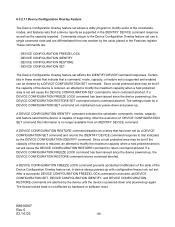
... that the device is supported and enabled can be cleared by a DEVICE CONFIGURATION SET command. If a DEVICE CONFIGURATION FREEZE LOCK command has been issued since the device powered-up, the DEVICE CONFIGURATION RESTORE command returns command aborted. A DEVICE CONFIGURATION IDENTIFY command indicates the selectable commands, modes, capacity, and feature sets that a command, mode, capacity, or feature set is capable of DEVICE CONFIGURATION SET command this information is executed, all DEVICE CONFIGURATION SET, DEVICE CONFIGURATION IDENTIFY, and DEVICE CONFIGURATION RESTORE commands are...
... that the device is supported and enabled can be cleared by a DEVICE CONFIGURATION SET command. If a DEVICE CONFIGURATION FREEZE LOCK command has been issued since the device powered-up, the DEVICE CONFIGURATION RESTORE command returns command aborted. A DEVICE CONFIGURATION IDENTIFY command indicates the selectable commands, modes, capacity, and feature sets that a command, mode, capacity, or feature set is capable of DEVICE CONFIGURATION SET command this information is executed, all DEVICE CONFIGURATION SET, DEVICE CONFIGURATION IDENTIFY, and DEVICE CONFIGURATION RESTORE commands are...
Owners Manual
Page 89
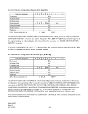
... the data returned from the execution of a DEVICE CONFIGURATION IDENTIFY command. DRV XX XX XX 00h 0 : DRV0 1:DRV1 The DEVICE CONFIGURATION RESTORE command disables any setting previously made by a DEVICE CONFIGURATION SET command and returns the content of the IDENTIFY DEVICE command response to the original settings as indicated by a SET MAX ADDRESS command, the device returns command aborted. 6.3.2.11.2 Device Configuration Freeze Lock [B1h, Sub 01h] Task File Registers Command Cylinder High Cylinder Low Device/Head Sector Number Sector Count Features DRV : Device selection...
... the data returned from the execution of a DEVICE CONFIGURATION IDENTIFY command. DRV XX XX XX 00h 0 : DRV0 1:DRV1 The DEVICE CONFIGURATION RESTORE command disables any setting previously made by a DEVICE CONFIGURATION SET command and returns the content of the IDENTIFY DEVICE command response to the original settings as indicated by a SET MAX ADDRESS command, the device returns command aborted. 6.3.2.11.2 Device Configuration Freeze Lock [B1h, Sub 01h] Task File Registers Command Cylinder High Cylinder Low Device/Head Sector Number Sector Count Features DRV : Device selection...


