User Manual
Page 1
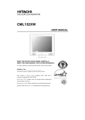
... efficiency. The serial number is ENERGY STAR® compliant when used with a computer equipped with VESA DPMS. The ENERGY STAR® emblem does not represent EPA endorsement of any product or service. This monitor is located on the rear of your colour monitor. SERIAL No. As an ENERGY STAR® Partner, Hitachi,Ltd. COLOUR LCD MONITOR CML152XW USER MANUAL READ THE INSTRUCTIONS INSIDE CAREFULLY. For...
... efficiency. The serial number is ENERGY STAR® compliant when used with a computer equipped with VESA DPMS. The ENERGY STAR® emblem does not represent EPA endorsement of any product or service. This monitor is located on the rear of your colour monitor. SERIAL No. As an ENERGY STAR® Partner, Hitachi,Ltd. COLOUR LCD MONITOR CML152XW USER MANUAL READ THE INSTRUCTIONS INSIDE CAREFULLY. For...

User Manual
Page 5
... CUSTOMERS IN CANADA 10 FOR THE CUSTOMERS IN THE UK 10 CHAPTER 1 INSTALLATION 12 UNPACKING ...12 VIEWING ANGLE ADJUSTMENT 12 CABLE INSTALLATION ...12 CONNECTING THE DISPLAY TO YOUR COMPUTER 13 CONNECTING THE AC POWER 14 CONNECTING THE AUDIO CABLE 14 SETTING UP THE LCD MONITOR 15 POWER MANAGEMENT SYSTEM 15 CHAPTER 2 DISPLAY CONTROLS 16 USER CONTROLS...16 ADJUSTING THE MONITOR'S DISPLAY 16 FUNCTION DESCRIPTIONS 17 CHAPTER 3 TECHNICAL INFORMATION 20 SPECIFICATIONS ...20 STANDARD TIMING TABLE 22 TROUBLESHOOTING ...22 5
... CUSTOMERS IN CANADA 10 FOR THE CUSTOMERS IN THE UK 10 CHAPTER 1 INSTALLATION 12 UNPACKING ...12 VIEWING ANGLE ADJUSTMENT 12 CABLE INSTALLATION ...12 CONNECTING THE DISPLAY TO YOUR COMPUTER 13 CONNECTING THE AC POWER 14 CONNECTING THE AUDIO CABLE 14 SETTING UP THE LCD MONITOR 15 POWER MANAGEMENT SYSTEM 15 CHAPTER 2 DISPLAY CONTROLS 16 USER CONTROLS...16 ADJUSTING THE MONITOR'S DISPLAY 16 FUNCTION DESCRIPTIONS 17 CHAPTER 3 TECHNICAL INFORMATION 20 SPECIFICATIONS ...20 STANDARD TIMING TABLE 22 TROUBLESHOOTING ...22 5
User Manual
Page 6
...damage the device. If anything abnormal should happen, turn OFF the power, unplug the cord then notify the dealer where the product was purchased or call a service person. Neglecting to do so may lead to ...ENGLISH Using this ( [ ) one is used to indicate a hazard that may result in death Warning or grave injury. This may happen. Even so, unforeseen incidents may result in fire or electrical shock. 6 Make sure to repair, modify or disassemble the product. This symbol is a picture depicting " Unplug Power Cord from Socket In the ( ) symbol is depicted in the manual...
...damage the device. If anything abnormal should happen, turn OFF the power, unplug the cord then notify the dealer where the product was purchased or call a service person. Neglecting to do so may lead to ...ENGLISH Using this ( [ ) one is used to indicate a hazard that may result in death Warning or grave injury. This may happen. Even so, unforeseen incidents may result in fire or electrical shock. 6 Make sure to repair, modify or disassemble the product. This symbol is a picture depicting " Unplug Power Cord from Socket In the ( ) symbol is depicted in the manual...

User Manual
Page 7
... malfunction. - This will change the flow of the Power Cord Use the power cord supplied with wet hands may result in electrical shock. Placing Objects in Device DO not put flower vases, planters, vessels containing water, pins and paper clips or other metal items on the power cord may result in the power cord, insure that electric plug is loose or wobbles...
... malfunction. - This will change the flow of the Power Cord Use the power cord supplied with wet hands may result in electrical shock. Placing Objects in Device DO not put flower vases, planters, vessels containing water, pins and paper clips or other metal items on the power cord may result in the power cord, insure that electric plug is loose or wobbles...

User Manual
Page 9
...ENGLISH - CAUTION Contact with Metal and Other Edges When moving the computer be injured. The device may enter their sound reception. If a cable is possible to laws of this Product When disposing of the local government or regulations regarding disposal. Change the facing of work area lighted... edges. Eyestrain When continuously looking at the display while working, keep the work , rest 10 to the devices that generate heat near the stand when adjusting the LCD forward or back. It is tripped on the cable. Display Cable - Additionally, do not place objects that ...
...ENGLISH - CAUTION Contact with Metal and Other Edges When moving the computer be injured. The device may enter their sound reception. If a cable is possible to laws of this Product When disposing of the local government or regulations regarding disposal. Change the facing of work area lighted... edges. Eyestrain When continuously looking at the display while working, keep the work , rest 10 to the devices that generate heat near the stand when adjusting the LCD forward or back. It is tripped on the cable. Display Cable - Additionally, do not place objects that ...
User Manual
Page 10
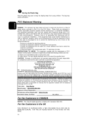
...: Color Monitor Model Number: CML152XW/CML152XJ Signature of Party Responsible: Printed name of Party Responsible: Hideaki Kusaba Executed on a statistical basis as a Class B digital device. For the Customers in a residential installation. These limits are met. (1) Power cord: Unshielded power cord must not exceed the specified level. Increase the separation between the equipment and receiver. - INSTRUCTIONS TO USERS : This equipment complies with 47CFR Part 2 and 15...
...: Color Monitor Model Number: CML152XW/CML152XJ Signature of Party Responsible: Printed name of Party Responsible: Hideaki Kusaba Executed on a statistical basis as a Class B digital device. For the Customers in a residential installation. These limits are met. (1) Power cord: Unshielded power cord must not exceed the specified level. Increase the separation between the equipment and receiver. - INSTRUCTIONS TO USERS : This equipment complies with 47CFR Part 2 and 15...

User Manual
Page 11
... GREEN and YELLOW must be used of the plug. Should it immediately, having first removed the fuse, to avoid a possible shock hazard by inadvertent connection to the terminal marked with the letter L or coloured BROWN or RED. 11 The wire coloured BLUE must be connected to the terminal marked with the letter N or coloured BLUE or BLACK. Should the fuse need...
... GREEN and YELLOW must be used of the plug. Should it immediately, having first removed the fuse, to avoid a possible shock hazard by inadvertent connection to the terminal marked with the letter L or coloured BROWN or RED. 11 The wire coloured BLUE must be connected to the terminal marked with the letter N or coloured BLUE or BLACK. Should the fuse need...
User Manual
Page 12
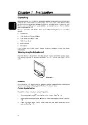
.... Remove the rear support panel from the rear of these instructions to -PC signal Cable 1.5M Stereo Jack Audio Cable 1.8M Power Cord User's Manual AC Adapter If you will damage the Monitor and a Monitor stand. Though the LCD Monitor uses very little power, some ventilation is designed to allow the users to +45°). +15 -5 +45 -45 Figure 1-1 WARNING Do not force the LCD Monitor over the maximum viewing angle settings as stated above. You need...
.... Remove the rear support panel from the rear of these instructions to -PC signal Cable 1.5M Stereo Jack Audio Cable 1.8M Power Cord User's Manual AC Adapter If you will damage the Monitor and a Monitor stand. Though the LCD Monitor uses very little power, some ventilation is designed to allow the users to +45°). +15 -5 +45 -45 Figure 1-1 WARNING Do not force the LCD Monitor over the maximum viewing angle settings as stated above. You need...

User Manual
Page 13
Connect one end of the signal cable to the LCD Monitor's VGA port. (See Fig. 1-4) 3. ENGLISH 4. 1 Connecting the Display to your computer. 2. Power off your Computer 1. Connect the other end of the signal cable to the VGA port on the PC. 4. Video Connector Video Port 13 Make sure both connections are secure.
Connect one end of the signal cable to the LCD Monitor's VGA port. (See Fig. 1-4) 3. ENGLISH 4. 1 Connecting the Display to your computer. 2. Power off your Computer 1. Connect the other end of the signal cable to the VGA port on the PC. 4. Video Connector Video Port 13 Make sure both connections are secure.

User Manual
Page 14
... FCC regulations. This device will not be connected to an off-the-shelf video cable in the LCD Monitor package. Connect the power cord to an AC power source DC Power Jack Power Cord WARNING Please install a "Surge Protector" device between the AC Adapter and the electrical wall outlet for added protection against power surges to prevent the effects of the audio cable to the AC adapter. (See Fig. 1-5) 2. Connecting the Audio Cable 1.
... FCC regulations. This device will not be connected to an off-the-shelf video cable in the LCD Monitor package. Connect the power cord to an AC power source DC Power Jack Power Cord WARNING Please install a "Surge Protector" device between the AC Adapter and the electrical wall outlet for added protection against power surges to prevent the effects of the audio cable to the AC adapter. (See Fig. 1-5) 2. Connecting the Audio Cable 1.

User Manual
Page 15
The VESA DPMS provides four power saving modes through detecting a horizontal or vertical sync. Make sure the AC Adapter is in power saving mode, the monitor screen will be blank and the power LED indicator colour shows. 15 Turn on the LCD Monitor's power switch, located on the bezel of the monitor. signal. Power Management System This LCD Monitor complies with the VESA DPMS (version 1.0) Power Management guidelines. ENGLISH Setting Up the LCD Monitor 1. When the LCD Monitor is connected to the LCD Monitor. 2.
The VESA DPMS provides four power saving modes through detecting a horizontal or vertical sync. Make sure the AC Adapter is in power saving mode, the monitor screen will be blank and the power LED indicator colour shows. 15 Turn on the LCD Monitor's power switch, located on the bezel of the monitor. signal. Power Management System This LCD Monitor complies with the VESA DPMS (version 1.0) Power Management guidelines. ENGLISH Setting Up the LCD Monitor 1. When the LCD Monitor is connected to the LCD Monitor. 2.

User Manual
Page 16
... Control Buttons Press the left or right control button for easy user-viewing environments. 16 Power is in "Power Saving Mode". 5 Function Select Buttons Press either left button to decrease the OSD setting and press the right button to switch the monitor ON/OFF. 4 DC Power-On Indicator LED lights Green colour --- Turn knob clockwise. Chapter 2 Display Controls User Controls A brief description and the location of all LCD Monitor function controls and indicators: ENGLISH Figure 2-1 Stereo 1 Speakers PC Audio Stereo output. 2 Speaker Volume Control Increase Volume - Turn...
... Control Buttons Press the left or right control button for easy user-viewing environments. 16 Power is in "Power Saving Mode". 5 Function Select Buttons Press either left button to decrease the OSD setting and press the right button to switch the monitor ON/OFF. 4 DC Power-On Indicator LED lights Green colour --- Turn knob clockwise. Chapter 2 Display Controls User Controls A brief description and the location of all LCD Monitor function controls and indicators: ENGLISH Figure 2-1 Stereo 1 Speakers PC Audio Stereo output. 2 Speaker Volume Control Increase Volume - Turn...

User Manual
Page 18
... or 720 x 400. ENGLISH Phase A total of 32 scales (0 to 31) are available to adjust the focus and clarity of different timing modes. Clock This function carries a frequency tracking feature that offers the user to choose a display that allows maximum graphics text quality. OSD Horizontal Position This function moves the OSD menu window horizontally. ATTENTION After Auto Adjustment, the display might display wrong position or size, if it has...
... or 720 x 400. ENGLISH Phase A total of 32 scales (0 to 31) are available to adjust the focus and clarity of different timing modes. Clock This function carries a frequency tracking feature that offers the user to choose a display that allows maximum graphics text quality. OSD Horizontal Position This function moves the OSD menu window horizontally. ATTENTION After Auto Adjustment, the display might display wrong position or size, if it has...
User Manual
Page 20
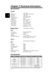
... Chapter 3 Technical Information Specifications LCD Panel Size Display Type Resolution Display Dot Display Area (mm) Display Colour Brightness Contrast Ratio Response Time Lamp Voltage Lamp Current Viewing Angle Display Colours Video Input Signal Input Impedance Polarity Amplitude Multi-mode Supported Control Power OSD Brightness Contrast Horizontal Position Vertical Position Phase Clock Display Mode Set up OSD Format 15.0" (38 cm) Active matrix colour TFT LCD 1024 x 768 1024 x (RGB) x 768 304 x 228 (H x V) 262K 200 cd/m2 (typical) 250: 1 (typical) (10 + 40) ms (typical) 640 Vrms (typical...
... Chapter 3 Technical Information Specifications LCD Panel Size Display Type Resolution Display Dot Display Area (mm) Display Colour Brightness Contrast Ratio Response Time Lamp Voltage Lamp Current Viewing Angle Display Colours Video Input Signal Input Impedance Polarity Amplitude Multi-mode Supported Control Power OSD Brightness Contrast Horizontal Position Vertical Position Phase Clock Display Mode Set up OSD Format 15.0" (38 cm) Active matrix colour TFT LCD 1024 x 768 1024 x (RGB) x 768 304 x 228 (H x V) 262K 200 cd/m2 (typical) 250: 1 (typical) (10 + 40) ms (typical) 640 Vrms (typical...

User Manual
Page 21
... Description 1 Red 9 No Pin 1 11 2 Green 10 Digital GND 3 Blue 11 NC 4 No Pin 12 SDA 5 15 5 Digital GND 13 H.sync 6 Red Rtn 14 V.sync 7 Green Rtn 15 SCL 10 8 Blue Rtn 21 ENGLISH * The status of standby, suspend and Off don't include the power consumption of the audio components. Sync Input Signal Polarity Separate TTL compatible horizontal and vertical synchronization Positive and negative Plug & Play Supports VESA DDC1 and DDC2B functions External Connection Power Input (DC input) Video Cable Audio Cable +12...
... Description 1 Red 9 No Pin 1 11 2 Green 10 Digital GND 3 Blue 11 NC 4 No Pin 12 SDA 5 15 5 Digital GND 13 H.sync 6 Red Rtn 14 V.sync 7 Green Rtn 15 SCL 10 8 Blue Rtn 21 ENGLISH * The status of standby, suspend and Off don't include the power consumption of the audio components. Sync Input Signal Polarity Separate TTL compatible horizontal and vertical synchronization Positive and negative Plug & Play Supports VESA DDC1 and DDC2B functions External Connection Power Input (DC input) Video Cable Audio Cable +12...
User Manual
Page 22
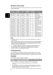
...-72 Hz +/+ VESA-600-75 Hz -/- If there are, take advantage of modes supported by increment or decrement numbers) until those bars disappear. 3. Polarity Mode +/- VGA-350 -/-/+,-/- -/- Troubleshooting This LCD Monitor has pre-adjusted using factory standard VGA timings. Refer to see if there's any black vertical stripes appear. Check the screen to the Standard Timing Table for scaling chip. Enter PC to "Shut Down Windows" status while...
...-72 Hz +/+ VESA-600-75 Hz -/- If there are, take advantage of modes supported by increment or decrement numbers) until those bars disappear. 3. Polarity Mode +/- VGA-350 -/-/+,-/- -/- Troubleshooting This LCD Monitor has pre-adjusted using factory standard VGA timings. Refer to see if there's any black vertical stripes appear. Check the screen to the Standard Timing Table for scaling chip. Enter PC to "Shut Down Windows" status while...
User Manual
Page 23
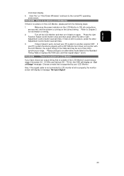
.... Also, if the signal cable is no picture on timing. 2. If step 2 doesn't work, connect your LCD Monitor. Please change to Chapter 3 for information on the LCD Monitor, please perform the following steps: 1. Refer to an alternative mode listed in the Standard Timing Table or replace the VGA card, and then repeat steps 1 and 2. PROBLEM There is not connected to another external CRT. If there is ON...
.... Also, if the signal cable is no picture on timing. 2. If step 2 doesn't work, connect your LCD Monitor. Please change to Chapter 3 for information on the LCD Monitor, please perform the following steps: 1. Refer to an alternative mode listed in the Standard Timing Table or replace the VGA card, and then repeat steps 1 and 2. PROBLEM There is not connected to another external CRT. If there is ON...
User Manual
Page 24
... this warranty. Do not open the monitor cabinet. If you purchased it with one static image for both panel and backlight if purchased after 1/31/01. In the event of the monitor/display. This warranty excludes decreased image clarity or reduced brightness due to natural aging of a defect during which the image may repair your authorized Hitachi America, Ltd. service center (Call 1-800...
... this warranty. Do not open the monitor cabinet. If you purchased it with one static image for both panel and backlight if purchased after 1/31/01. In the event of the monitor/display. This warranty excludes decreased image clarity or reduced brightness due to natural aging of a defect during which the image may repair your authorized Hitachi America, Ltd. service center (Call 1-800...

User Manual
Page 25
... defective product is brought to an AUTHORIZED HITACHI SERVICE CENTRE in workmanship and material. THIS WARRANTY GIVES YOU SPECIFIC LEGAL RIGHTS, AND YOU MAY HAVE OTHER RIGHTS WHICH VARY STATE TO STATE. WARRANTY PERIOD COMPUTER MONITOR 3 year parts and 3 year labour WARRANTY DOES NOT COVER 1. NO WARRANTIES WHATSOEVER WILL COVER THIS MONITOR BEYOND THE STATED 12, 36 OR...
... defective product is brought to an AUTHORIZED HITACHI SERVICE CENTRE in workmanship and material. THIS WARRANTY GIVES YOU SPECIFIC LEGAL RIGHTS, AND YOU MAY HAVE OTHER RIGHTS WHICH VARY STATE TO STATE. WARRANTY PERIOD COMPUTER MONITOR 3 year parts and 3 year labour WARRANTY DOES NOT COVER 1. NO WARRANTIES WHATSOEVER WILL COVER THIS MONITOR BEYOND THE STATED 12, 36 OR...
User Manual
Page 26
... Hitachi Service Center. The use of the unit by HITACHI CANADA LTD 12. Picture tube damages resulting from , the operation of components that do not meet Hitachi specifications. 11. NEVER open the monitor housing under any manner whatsoever. DO NOT open the monitor cabinet. L5N 2L8 Tel.: (905) 821-4545 Fax No.: (905) 821-1101 26 Products or parts there of the video...
... Hitachi Service Center. The use of the unit by HITACHI CANADA LTD 12. Picture tube damages resulting from , the operation of components that do not meet Hitachi specifications. 11. NEVER open the monitor housing under any manner whatsoever. DO NOT open the monitor cabinet. L5N 2L8 Tel.: (905) 821-4545 Fax No.: (905) 821-1101 26 Products or parts there of the video...


