
Instruction Manual
Page 4
...job for best and safest performance. Don't leave tool until you are removed from work area well lighted. 6. Keep proper footing and balance at HITACHI. ALWAYS operate the Band Saw in working order. 3. REMOVE ADJUSTING KEYS AND WRENCHES. KEEP WORK AREA CLEAN. DON'T USE IN DANGEROUS ENVIRONMENT. ... tipped or if the cutting tool is damaged should be carefully checked to overheat. Make sure your hand and it was not designed. 10. Use dust collection systems whenever possible. When using your extension cord is in . 17. Use clamps or a vise to do not...
...job for best and safest performance. Don't leave tool until you are removed from work area well lighted. 6. Keep proper footing and balance at HITACHI. ALWAYS operate the Band Saw in working order. 3. REMOVE ADJUSTING KEYS AND WRENCHES. KEEP WORK AREA CLEAN. DON'T USE IN DANGEROUS ENVIRONMENT. ... tipped or if the cutting tool is damaged should be carefully checked to overheat. Make sure your hand and it was not designed. 10. Use dust collection systems whenever possible. When using your extension cord is in . 17. Use clamps or a vise to do not...
Instruction Manual
Page 5
... that is clear of least resistance for 120V operation. Never use a 15 Amp time delay fuse or circuit breaker. If there is 1/8 inch above the workpiece. 7. Remove the switch key and unplug the saw OFF. Wear eye protection. 2. Maintain proper adjustment of electric shock....clothing. 3. The conductor with green insulation (with ALL local codes and ordinances. Avoid awkward operation and hand positions to support the workpiece. 10. Store it immediately. Do not remove jammed cutoff pieces until the problem has been located and corrected. 16. Connect to a 120V, ...
... that is clear of least resistance for 120V operation. Never use a 15 Amp time delay fuse or circuit breaker. If there is 1/8 inch above the workpiece. 7. Remove the switch key and unplug the saw OFF. Wear eye protection. 2. Maintain proper adjustment of electric shock....clothing. 3. The conductor with green insulation (with ALL local codes and ordinances. Avoid awkward operation and hand positions to support the workpiece. 10. Store it immediately. Do not remove jammed cutoff pieces until the problem has been located and corrected. 16. Connect to a 120V, ...
Instruction Manual
Page 6
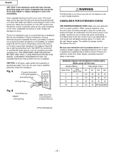
... indoor use one illustrated in feet More Than Not More Than 25′ 50′ 100′ 150′ 0 6 18 16 16 14 6 10 18 16 14 12 10 12 16 16 14 12 12 16 14 12 Not Applicable 2-Prong Receptacle -6- The adapter (Figure B) has a rigid lug extending from sharp objects...
... indoor use one illustrated in feet More Than Not More Than 25′ 50′ 100′ 150′ 0 6 18 16 16 14 6 10 18 16 14 12 10 12 16 16 14 12 12 16 14 12 Not Applicable 2-Prong Receptacle -6- The adapter (Figure B) has a rigid lug extending from sharp objects...

Instruction Manual
Page 10
...the saw blade teeth tips that are , the greater the set. Leading Edge Kerf Surface Relief Cut Saw Blade Path Workpiece Trailing Edge - 10 - English GLOSSARY OF TERMS BAND SAW TERMS BLADE GUIDES - Support the blade and keep the machine free from the outside edge, allowing ...child safety lock. RELIEF CUT - SAWDUST PORT - Helps keep it after adjusting the upper guide assembly to make thinner workpiece. TABLE LOCK KNOB - TILT (BEVEL) SCALE - Shows the degree the table is turned on which the workpiece rests while performing a cutting or sanding operation. Use it from...
...the saw blade teeth tips that are , the greater the set. Leading Edge Kerf Surface Relief Cut Saw Blade Path Workpiece Trailing Edge - 10 - English GLOSSARY OF TERMS BAND SAW TERMS BLADE GUIDES - Support the blade and keep the machine free from the outside edge, allowing ...child safety lock. RELIEF CUT - SAWDUST PORT - Helps keep it after adjusting the upper guide assembly to make thinner workpiece. TABLE LOCK KNOB - TILT (BEVEL) SCALE - Shows the degree the table is turned on which the workpiece rests while performing a cutting or sanding operation. Use it from...

Instruction Manual
Page 57
...Soc. Bolt M6*1.0*16 3 Motor 1 Flat Key 4*4*20 1 Washer 1 Strain Relief 1 Tracking Plate 1 Grommet 1 Hex Nut M12-1.75 1 Set Screw (Headless) M6*10 4 Cam Ass'y 1 Upper Guide Holder Ass'y 1 Knob 1 Part No. Pan Hd. Hd. PARTS LIST FOR SCHEMATIC A MODEL NO. Bolt M8*1.25-20 4 ...327543 0045 Hinge Pivot 1 327544 0046 Sleeve 1 327545 0047 Soc. Hd. PARTS LIST 10″ Band Saw ALWAYS ORDER BY PART NO. Screw M5*0.8-8 13 327541 0043 Spring Washer M8 4 327542 0044 Soc. NUMBER. Hd. Description Size...
...Soc. Bolt M6*1.0*16 3 Motor 1 Flat Key 4*4*20 1 Washer 1 Strain Relief 1 Tracking Plate 1 Grommet 1 Hex Nut M12-1.75 1 Set Screw (Headless) M6*10 4 Cam Ass'y 1 Upper Guide Holder Ass'y 1 Knob 1 Part No. Pan Hd. Hd. PARTS LIST FOR SCHEMATIC A MODEL NO. Bolt M8*1.25-20 4 ...327543 0045 Hinge Pivot 1 327544 0046 Sleeve 1 327545 0047 Soc. Hd. PARTS LIST 10″ Band Saw ALWAYS ORDER BY PART NO. Screw M5*0.8-8 13 327541 0043 Spring Washer M8 4 327542 0044 Soc. NUMBER. Hd. Description Size...

Instruction Manual
Page 59
... .D. Bolt Crank Handle Table Table Insert Table Locking Insert Wing Bolt Miter Gauge Ass'y Flat Washer Flat Washer Size Qty 1 M5 1 1 M8 4 1 1 M5*0.8-10 2 1 1 1 1 M6*1.0-20 1 1 M6*16*1.5 1 M12 1 - 59 - AND I .D. 0001 0002 0003 0004 0005 0006 0007 0008 0009 0010 0011 0012 0013... 0014 0015 Description Head Mounting Bracket Base Plate Pointer Ass'y Flat Washer Soc. PARTS LIST 10″ Band Saw ALWAYS ORDER BY PART NO. Hd. Bolt Spring Washer Spring Pin Size Qty 1 2 1 M5 2 M5...
... .D. Bolt Crank Handle Table Table Insert Table Locking Insert Wing Bolt Miter Gauge Ass'y Flat Washer Flat Washer Size Qty 1 M5 1 1 M8 4 1 1 M5*0.8-10 2 1 1 1 1 M6*1.0-20 1 1 M6*16*1.5 1 M12 1 - 59 - AND I .D. 0001 0002 0003 0004 0005 0006 0007 0008 0009 0010 0011 0012 0013... 0014 0015 Description Head Mounting Bracket Base Plate Pointer Ass'y Flat Washer Soc. PARTS LIST 10″ Band Saw ALWAYS ORDER BY PART NO. Hd. Bolt Spring Washer Spring Pin Size Qty 1 2 1 M5 2 M5...
Parts List
Page 2
...0034 Insert 1 327533 0035 Upper Guide Bracket 1 327534 0036 Blade Guard W/Lamp 1 327535 0037 Lamp Cover 1 327536 0038 Impeller 1 327537 0039 Soc. Bolt M6*1.0-10 1 327546 0048 Flat Washer M6 1 327547 0049 Shaft 1 327548 0050 Link 1 327549 0051 Bracket 1 327550 0052 Soc. Bolt M6*1.0*16 3 Motor 1 Flat ... Lock Washer 327540 0042 Cr. Hd. Bolt M8*1.25-20 4 327543 0045 Hinge Pivot 1 327544 0046 Sleeve 1 327545 0047 Soc. PARTS LIST 10″ Band Saw ALWAYS ORDER BY PART NO. Re. PARTS LIST FOR SCHEMATIC A MODEL NO. AND I .D. 0001 0002 0003 0004 0005 0006...
...0034 Insert 1 327533 0035 Upper Guide Bracket 1 327534 0036 Blade Guard W/Lamp 1 327535 0037 Lamp Cover 1 327536 0038 Impeller 1 327537 0039 Soc. Bolt M6*1.0-10 1 327546 0048 Flat Washer M6 1 327547 0049 Shaft 1 327548 0050 Link 1 327549 0051 Bracket 1 327550 0052 Soc. Bolt M6*1.0*16 3 Motor 1 Flat ... Lock Washer 327540 0042 Cr. Hd. Bolt M8*1.25-20 4 327543 0045 Hinge Pivot 1 327544 0046 Sleeve 1 327545 0047 Soc. PARTS LIST 10″ Band Saw ALWAYS ORDER BY PART NO. Re. PARTS LIST FOR SCHEMATIC A MODEL NO. AND I .D. 0001 0002 0003 0004 0005 0006...

Parts List
Page 4
... MODEL NO. Bolt Crank Handle Table Table Insert Table Locking Insert Wing Bolt Miter Gauge Ass'y Flat Washer Flat Washer Size Qty 1 M5 1 1 M8 4 1 1 M5*0.8-10 2 1 1 1 1 M6*1.0-20 1 1 M6*16*1.5 1 M12 1 - 59 - Hd. Bolt Hex Hd. Hd. AND I .D. 0001 0002 0003 0004 0005 0006... 0007 0008 0009 0010 0011 0012 0013 0014 0015 Description Head Mounting Bracket Base Plate Pointer Ass'y Flat Washer Soc. CB6Y Part No. 327559 327560 327561 327562 327563 327564 327565 327566 327567 327568 327569 327570 327571...
... MODEL NO. Bolt Crank Handle Table Table Insert Table Locking Insert Wing Bolt Miter Gauge Ass'y Flat Washer Flat Washer Size Qty 1 M5 1 1 M8 4 1 1 M5*0.8-10 2 1 1 1 1 M6*1.0-20 1 1 M6*16*1.5 1 M12 1 - 59 - Hd. Bolt Hex Hd. Hd. AND I .D. 0001 0002 0003 0004 0005 0006... 0007 0008 0009 0010 0011 0012 0013 0014 0015 Description Head Mounting Bracket Base Plate Pointer Ass'y Flat Washer Soc. CB6Y Part No. 327559 327560 327561 327562 327563 327564 327565 327566 327567 327568 327569 327570 327571...


