Instruction Manual
Page 3
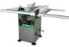
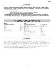
It must be connected to the table saw, use proper circuit protection. Before using your exposure to follow these chemicals, work in a well-ventilated area and work . Right 30", Left 18" Blade Size 10" Rip Scale YES Rip Fence YES Miter Gauge YES Maximum Cut Depth @ 90 3-3/8" Maximum...power cord immediately if it is wired at the factory for 110-120/220-240 Volt operation. This table saw . - 3 - English WARNING Some dust created by power sanding, sawing, grinding, drilling and other construction activities contains chemicals known to the state of California to cause cancer,...
It must be connected to the table saw, use proper circuit protection. Before using your exposure to follow these chemicals, work in a well-ventilated area and work . Right 30", Left 18" Blade Size 10" Rip Scale YES Rip Fence YES Miter Gauge YES Maximum Cut Depth @ 90 3-3/8" Maximum...power cord immediately if it is wired at the factory for 110-120/220-240 Volt operation. This table saw . - 3 - English WARNING Some dust created by power sanding, sawing, grinding, drilling and other construction activities contains chemicals known to the state of California to cause cancer,...

Instruction Manual
Page 4
...cutters, etc. 13. MAINTAIN TOOLS WITH CARE. KEEP WORK AREA CLEAN. It will do a job for which it is not designed. 10. DISCONNECT TOOLS before turning ON. 16. Dust generated from certain materials can throw debris into your eyes that identifies important safety.... 7. Check for this entire Operator's Manual. Feed work into the power supply. 20. English POWER TOOL SAFETY WARNING Before using your table saw . accessories. REMOVE ADJUSTING KEYS AND WRENCHES. NEVER LEAVE TOOL RUNNING UNATTENDED. Do not leave the tool before plugging tool into a blade ...
...cutters, etc. 13. MAINTAIN TOOLS WITH CARE. KEEP WORK AREA CLEAN. It will do a job for which it is not designed. 10. DISCONNECT TOOLS before turning ON. 16. Dust generated from certain materials can throw debris into your eyes that identifies important safety.... 7. Check for this entire Operator's Manual. Feed work into the power supply. 20. English POWER TOOL SAFETY WARNING Before using your table saw . accessories. REMOVE ADJUSTING KEYS AND WRENCHES. NEVER LEAVE TOOL RUNNING UNATTENDED. Do not leave the tool before plugging tool into a blade ...
Instruction Manual
Page 5
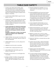
... cloth should be used to a complete stop. 10. NEVER CUT METALS or materials that is twisted, warped or does not have any part of the saw blade. ALWAYS USE IN A WELL-VENTILATED AREA. Do not leave the saw OFF. Turn power switch OFF immediately to ASSEMBLY AND... the rip fence when crosscutting. 8. Remove sawdust frequently. Attach a vacuum to clean plastic parts. NEVER LEAVE THE SAW RUNNING UNATTENDED. English TABLE SAW SAFETY 1. ALWAYS USE SAW BLADE GUARD, splitter and antikickback pawls for every operation for which the blade cuts completely through the workpiece when ripping ...
... cloth should be used to a complete stop. 10. NEVER CUT METALS or materials that is twisted, warped or does not have any part of the saw blade. ALWAYS USE IN A WELL-VENTILATED AREA. Do not leave the saw OFF. Turn power switch OFF immediately to ASSEMBLY AND... the rip fence when crosscutting. 8. Remove sawdust frequently. Attach a vacuum to clean plastic parts. NEVER LEAVE THE SAW RUNNING UNATTENDED. English TABLE SAW SAFETY 1. ALWAYS USE SAW BLADE GUARD, splitter and antikickback pawls for every operation for which the blade cuts completely through the workpiece when ripping ...

Instruction Manual
Page 6
...10 18 16 14 12 10 12 12 16 16 16 14 12 14 12 Not Recommended Grounding Prong GUIDELINES FOR EXTENSION CORDS Properly Grounded 3-Prong Receptacle Any extension cord used for your extension cords from power source Before connecting the saw to a known ground. 2-Prong Receptacle 240V OPERATION The table saw...wire) with the green insulation (with 240V plug to a live terminal. Be sure your local Hitachi Authorized Service Center or resistance for electric current and reduces the risk of the saw at prongs and one heavy enough to a 120V, 15 Amp circuit and use a separate ...
...10 18 16 14 12 10 12 12 16 16 16 14 12 14 12 Not Recommended Grounding Prong GUIDELINES FOR EXTENSION CORDS Properly Grounded 3-Prong Receptacle Any extension cord used for your extension cords from power source Before connecting the saw to a known ground. 2-Prong Receptacle 240V OPERATION The table saw...wire) with the green insulation (with 240V plug to a live terminal. Be sure your local Hitachi Authorized Service Center or resistance for electric current and reduces the risk of the saw at prongs and one heavy enough to a 120V, 15 Amp circuit and use a separate ...

Instruction Manual
Page 7
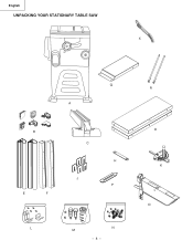
... LOOSE PARTS ITEM DESCRIPTION A Table saw assembly B Rail cover C Rip fence D Table extension wing E Front table extension rail F Rear table extension rail H Blade wrench J Adhesive washer K Miter gauge L Storage hardware bag M Handle hardware bag N Table extension hardware bag O Blade guard and splitter ass'y QUANTITY 1 6 1 2 2 2 1 5 1 1 1 1 1 If any packing... recommended accessories for , before discarding any part is missing or damaged, do not attempt to assemble the table saw, plug in the power cord, or turn the switch ON until the missing or damaged part is obtained and is 13...
... LOOSE PARTS ITEM DESCRIPTION A Table saw assembly B Rail cover C Rip fence D Table extension wing E Front table extension rail F Rear table extension rail H Blade wrench J Adhesive washer K Miter gauge L Storage hardware bag M Handle hardware bag N Table extension hardware bag O Blade guard and splitter ass'y QUANTITY 1 6 1 2 2 2 1 5 1 1 1 1 1 If any packing... recommended accessories for , before discarding any part is missing or damaged, do not attempt to assemble the table saw, plug in the power cord, or turn the switch ON until the missing or damaged part is obtained and is 13...
Instruction Manual
Page 8
R D K O English UNPACKING YOUR STATIONARY TABLE SAW X Q A B E F C H J P L M N - 8 -
R D K O English UNPACKING YOUR STATIONARY TABLE SAW X Q A B E F C H J P L M N - 8 -
Instruction Manual
Page 9
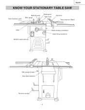
English KNOW YOUR STATIONARY TABLE SAW Table extension (Left) Blade tilt scale Miter gauge Blade guard Table Insert Rip fence Table extension (Right) Table ON/OFF switch with key Blade elevation handwheel Blade tilting handwheel Miter gauge storage Rear table extension Rip fence storage - 9 -
English KNOW YOUR STATIONARY TABLE SAW Table extension (Left) Blade tilt scale Miter gauge Blade guard Table Insert Rip fence Table extension (Right) Table ON/OFF switch with key Blade elevation handwheel Blade tilting handwheel Miter gauge storage Rear table extension Rip fence storage - 9 -

Instruction Manual
Page 10
... angle cuts. A cut . - 10 - FREEHAND - TABLE SCALE - A guide used for crosscutting operations that has hardened. KERF - SET - The distance between 0° to any angle between two saw motor if it overheats or overloads. BLADE TILTING HANDWHEEL - Tilts the blade to 45° for bevel cuts. English GLOSSARY OF TERMS HITACHI PROFESSIONAL TABLE SAW TERMS MITER GAUGE...
... angle cuts. A cut . - 10 - FREEHAND - TABLE SCALE - A guide used for crosscutting operations that has hardened. KERF - SET - The distance between 0° to any angle between two saw motor if it overheats or overloads. BLADE TILTING HANDWHEEL - Tilts the blade to 45° for bevel cuts. English GLOSSARY OF TERMS HITACHI PROFESSIONAL TABLE SAW TERMS MITER GAUGE...

Instruction Manual
Page 11
... the front rail to connect the two half 3 front rail. 5. When the front rail is removed from the cabinet stand. 4. ASSEMBLY THE TABLE EXTENSION (FIG. Place bolts (2) and thread in front of the front rail. Assembly the front rail (Fig.... (4) 2 through the slot of the table saw table, across the table extension. - 11 - 5 4 6 3 4 2 1 B) Fig. B-1 WARNING To avoid injury, beware the weight of table rails assemblies are different. Place a straight edge or combination square on the saw to the saw table. English ASSEMBLY AND ADJUSTMENTS REMOVE THE STYROFOAM...
... the front rail to connect the two half 3 front rail. 5. When the front rail is removed from the cabinet stand. 4. ASSEMBLY THE TABLE EXTENSION (FIG. Place bolts (2) and thread in front of the front rail. Assembly the front rail (Fig.... (4) 2 through the slot of the table saw table, across the table extension. - 11 - 5 4 6 3 4 2 1 B) Fig. B-1 WARNING To avoid injury, beware the weight of table rails assemblies are different. Place a straight edge or combination square on the saw to the saw table. English ASSEMBLY AND ADJUSTMENTS REMOVE THE STYROFOAM...
Instruction Manual
Page 12
... Place the screws (9) to adjust the rear table extension (3) for alignment. Loosen the nuts (7) and screws (4) to the slot of the table, and align the splitter mounting holes to the rear table reails (8). 5. BLADE TILTING HANDWHEEL (FIG. Fig. C 4 5 6 8 9 3 7 1 2 10 BLADE GUARD ASSEMBLY (FIG. Return the blade ...(2) do not pull on handle just turn and move the handwheel (1) to 45° on the saw table, aligning with the holes in place for the rear table extension is disconnected from the power source outlet. • When installing the blade guard, cover the ...
... Place the screws (9) to adjust the rear table extension (3) for alignment. Loosen the nuts (7) and screws (4) to the slot of the table, and align the splitter mounting holes to the rear table reails (8). 5. BLADE TILTING HANDWHEEL (FIG. Fig. C 4 5 6 8 9 3 7 1 2 10 BLADE GUARD ASSEMBLY (FIG. Return the blade ...(2) do not pull on handle just turn and move the handwheel (1) to 45° on the saw table, aligning with the holes in place for the rear table extension is disconnected from the power source outlet. • When installing the blade guard, cover the ...
Instruction Manual
Page 13
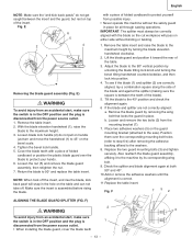
...tilting lock knob and turning the bevel tilting handwheel counterclockwise, and then lock into position. 4. Remove the table insert. 2. Cover the blade teeth with a piece of folded cardboard to protect yourself from the mounting...the maximum height. 3. Fig. With the blade elevation handwheel (1), raise the blade to the saw). Loosen the nut (5) and remove the blade guard assembly, then retighten the nut. 7. ... washers. 8. Check the splitter and blade alignment again at both 90O and 45O . 10.Add or remove the adhesive washers until the alignment is assembled before rising the blade....
...tilting lock knob and turning the bevel tilting handwheel counterclockwise, and then lock into position. 4. Remove the table insert. 2. Cover the blade teeth with a piece of folded cardboard to protect yourself from the mounting...the maximum height. 3. Fig. With the blade elevation handwheel (1), raise the blade to the saw). Loosen the nut (5) and remove the blade guard assembly, then retighten the nut. 7. ... washers. 8. Check the splitter and blade alignment again at both 90O and 45O . 10.Add or remove the adhesive washers until the alignment is assembled before rising the blade....
Instruction Manual
Page 14
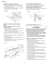
...teeth pointing forward to the 90° vertical position by pulling the wrench toward the rear of the table. 3. Replace the table insert and blade guard assembly. IMPORTANT: Do not operate this saw until the latch locks into place and the blade will no longer turn clockwise (toward the front ...the power source outlet. 1. If they are not, refer to the maximum height by turning the blade elevation handwheel clockwise. 2. Remove the table insert and raise the blade to page 13, Aligning The Blade Guard Splitter. Pull the motor locking lever (1) toward the rear of the...
...teeth pointing forward to the 90° vertical position by pulling the wrench toward the rear of the table. 3. Replace the table insert and blade guard assembly. IMPORTANT: Do not operate this saw until the latch locks into place and the blade will no longer turn clockwise (toward the front ...the power source outlet. 1. If they are not, refer to the maximum height by turning the blade elevation handwheel clockwise. 2. Remove the table insert and raise the blade to page 13, Aligning The Blade Guard Splitter. Pull the motor locking lever (1) toward the rear of the...
Instruction Manual
Page 16
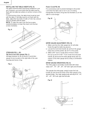
.... M 1 STORAGE (FIG. If not, loosen the lock knob handle (2) and move the body of the miter gauge to the power cord when the table saw housing and frame of wood. MITER GAUGE OPERATION (FIG. N) 1. Make a 90O cut to see if it is accurately constructed with a 4 mm hex. K) ...The table insert has been previously installed on the right side of the saw is not in a scrap piece of leg. L) Storage brackets for cord storage. Make sure that the table insert is 90O. Loosen the lock knob handle (2) and turn the...
.... M 1 STORAGE (FIG. If not, loosen the lock knob handle (2) and move the body of the miter gauge to the power cord when the table saw housing and frame of wood. MITER GAUGE OPERATION (FIG. N) 1. Make a 90O cut to see if it is accurately constructed with a 4 mm hex. K) ...The table insert has been previously installed on the right side of the saw is not in a scrap piece of leg. L) Storage brackets for cord storage. Make sure that the table insert is 90O. Loosen the lock knob handle (2) and turn the...

Instruction Manual
Page 17
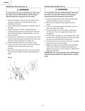
... fence on the handle to unlock, and slide the fence to the desired position, then push the handle down to the side of the table, and lower the front end over the front rail (2). Measurement shown by the indicator will cause the rip fence to come out of the...of alignment. O English RIP FENCE INDICATOR (FIG. If there is the most common position. Calibrations on the front of saw . RIP FENCE (FIG. O) 1. For adjustments, position the fence to either side of the table saw blade. Place the rear clamp (1) (Fig. Push the handle (3) down to the blade. 1. To change the ...
... fence on the handle to unlock, and slide the fence to the desired position, then push the handle down to the side of the table, and lower the front end over the front rail (2). Measurement shown by the indicator will cause the rip fence to come out of the...of alignment. O English RIP FENCE INDICATOR (FIG. If there is the most common position. Calibrations on the front of saw . RIP FENCE (FIG. O) 1. For adjustments, position the fence to either side of the table saw blade. Place the rear clamp (1) (Fig. Push the handle (3) down to the blade. 1. To change the ...

Instruction Manual
Page 18
...SWITCH (FIG. To lock the switch in the OFF position, grasp the end (or yellow part) of the table saw with the hose in place unless the vacuum is removed while the saw ON, lift switch cover (1) and insert the safety switch key (2) into the slot in on . S) WARNING...bevel lock knob (2) to cool, push in the switch. S 2 1 - 18 - R 1 OFF 2 ON 3 2 3 TILTING THE BLADE 1. DO NOT operate the saw . English OPERATION BASIC SAW OPERATIONS RAISE THE BLADE (FIG. R-1) The ON / OFF switch has a removal key. Move the switch (3) upward to secure. To prevent sawdust buildup inside the...
...SWITCH (FIG. To lock the switch in the OFF position, grasp the end (or yellow part) of the table saw with the hose in place unless the vacuum is removed while the saw ON, lift switch cover (1) and insert the safety switch key (2) into the slot in on . S) WARNING...bevel lock knob (2) to cool, push in the switch. S 2 1 - 18 - R 1 OFF 2 ON 3 2 3 TILTING THE BLADE 1. DO NOT operate the saw . English OPERATION BASIC SAW OPERATIONS RAISE THE BLADE (FIG. R-1) The ON / OFF switch has a removal key. Move the switch (3) upward to secure. To prevent sawdust buildup inside the...
Instruction Manual
Page 19
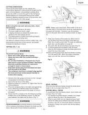
... fence, use one or more than 1/2" wide. When both of your thumbs touch the front edge of the table (2), finish the cut . • Do not allow familiarity or frequent use of your table saw ON and wait for the blade to come to cause a severe injury. • Keep both hands away from... miter gauge and store it in the "storage" compartment in the front of a second is set to the table. 3. Secure the rip fence to an angle other than the top of the table. 10.Never pull the piece back when the blade is tight. 3. Keep the workpiece away from the blade contact, never...
... fence, use one or more than 1/2" wide. When both of your thumbs touch the front edge of the table (2), finish the cut . • Do not allow familiarity or frequent use of your table saw ON and wait for the blade to come to cause a severe injury. • Keep both hands away from... miter gauge and store it in the "storage" compartment in the front of a second is set to the table. 3. Secure the rip fence to an angle other than the top of the table. 10.Never pull the piece back when the blade is tight. 3. Keep the workpiece away from the blade contact, never...

Instruction Manual
Page 20
...line with the blade turning. distance from the blade and the path of the saw to pull the workpiece back with the desired cut very long or short pieces. Keep the workpiece (2) against the table. WARNING Always position the larger surface of the workpiece. 3. V 1 3 with... 1 BEVEL CROSSCUTTING (FIG. Make sure the facing does not interfere with screws. Start the saw and wait for attaching an auxiliary facing (1) to make a simple outfeed support by clamping a piece of your table saw blade path, always stand to the desired angle, and tighten the blade bevel lock knob....
...line with the blade turning. distance from the blade and the path of the saw to pull the workpiece back with the desired cut very long or short pieces. Keep the workpiece (2) against the table. WARNING Always position the larger surface of the workpiece. 3. V 1 3 with... 1 BEVEL CROSSCUTTING (FIG. Make sure the facing does not interfere with screws. Start the saw and wait for attaching an auxiliary facing (1) to make a simple outfeed support by clamping a piece of your table saw blade path, always stand to the desired angle, and tighten the blade bevel lock knob....
Instruction Manual
Page 23
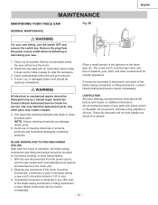
...safety, turn the saw cabinet and the motor. 2. Polish the saw where a pivot or threaded rod are permanently lubricated at the factory and require no additional lubrication. Avoid use of dry lubricant on the motor unit. 2. English MAINTENANCE MAINTAINING YOUR TABLE SAW Fig. These ... for service. EE GENERAL MAINTENANCE WARNING For your table saw table with pitch and gum remover. 4. A worn, cut, or damaged power cord should be kept clean and free of the blade raising mechanism or tilting mechanism, contact Hitachi Authorized Service Center immediately. - 23 - Use ...
...safety, turn the saw cabinet and the motor. 2. Polish the saw where a pivot or threaded rod are permanently lubricated at the factory and require no additional lubrication. Avoid use of dry lubricant on the motor unit. 2. English MAINTENANCE MAINTAINING YOUR TABLE SAW Fig. These ... for service. EE GENERAL MAINTENANCE WARNING For your table saw table with pitch and gum remover. 4. A worn, cut, or damaged power cord should be kept clean and free of the blade raising mechanism or tilting mechanism, contact Hitachi Authorized Service Center immediately. - 23 - Use ...

Instruction Manual
Page 72
...SPONGE WHEEL SET PLATE RETAINING CLIP LOCATION SEAT ARM BRACKET WASHER COLLAR POINTER ROLLING WHEEL PARTS LIST MODEL NO. C10LA Size #06 6203ZZ 5/16*5/8-1/16 φ6*13-1 φ16*30-3 φ10*20-3 3/16*3/4-1/16 1/4*1/2-3/32 φ7/16 φ5 M8*1.25-16 M6*1.0-12 M8*1.25-20 M10... CONNECTOR WIRE CONNECTOR CONNECTOR BOX COVER LEAD WIRE ASS'Y LEAD WIRE ASS'Y LEAD WIRE ASS'Y INSERT ASS'Y INSERT ASS'Y (DADO) HANDLE HEX. English 10" STATIONARY TABLE SAW PARTS LIST FOR SCHEMATIC HKU# I .D. HD. HD. CAP BOLT HEX. RE. ROUND WASHER HD. SCREW CAP HD. CAP BOLT WORM BEVEL GEAR...
...SPONGE WHEEL SET PLATE RETAINING CLIP LOCATION SEAT ARM BRACKET WASHER COLLAR POINTER ROLLING WHEEL PARTS LIST MODEL NO. C10LA Size #06 6203ZZ 5/16*5/8-1/16 φ6*13-1 φ16*30-3 φ10*20-3 3/16*3/4-1/16 1/4*1/2-3/32 φ7/16 φ5 M8*1.25-16 M6*1.0-12 M8*1.25-20 M10... CONNECTOR WIRE CONNECTOR CONNECTOR BOX COVER LEAD WIRE ASS'Y LEAD WIRE ASS'Y LEAD WIRE ASS'Y INSERT ASS'Y INSERT ASS'Y (DADO) HANDLE HEX. English 10" STATIONARY TABLE SAW PARTS LIST FOR SCHEMATIC HKU# I .D. HD. HD. CAP BOLT HEX. RE. ROUND WASHER HD. SCREW CAP HD. CAP BOLT WORM BEVEL GEAR...

Parts List
Page 1
...CR. TAPPING SCREW 726571 0KAA CR. RE. PAN HD. NUT 726598 0KMT HEX. NUT 726599 0KMU HEX. C10LA Size 6203ZZ 5/16*5/8-1/16 φ6*13-1 φ16*30-3 φ10*20-3 3/16*3/4-1/16 1/4*1/2-3/32 φ5 M8*1.25-20 M8*1.25-16 M10*1.5-20 M10*1.5-35 M6*1.0-6 M6...SCREW & WASHER 325967 0K5T CR. SOC. TAPPING SCREW 726577 0KCX CR. SCREW & WASHER 325966 0K4A CR. SCREW 726551 0K61 CR. English 10" STATIONARY TABLE SAW PARTS LIST FOR SCHEMATIC HKU# I .D. RE. NUT BALL BEARING DUST PLATE HANDLE WASHER SWITCH MOUNTING SWITCH BOX CIRCUIT BREAKER SWITCH REAR BRACKET...
...CR. TAPPING SCREW 726571 0KAA CR. RE. PAN HD. NUT 726598 0KMT HEX. NUT 726599 0KMU HEX. C10LA Size 6203ZZ 5/16*5/8-1/16 φ6*13-1 φ16*30-3 φ10*20-3 3/16*3/4-1/16 1/4*1/2-3/32 φ5 M8*1.25-20 M8*1.25-16 M10*1.5-20 M10*1.5-35 M6*1.0-6 M6...SCREW & WASHER 325967 0K5T CR. SOC. TAPPING SCREW 726577 0KCX CR. SCREW & WASHER 325966 0K4A CR. SCREW 726551 0K61 CR. English 10" STATIONARY TABLE SAW PARTS LIST FOR SCHEMATIC HKU# I .D. RE. NUT BALL BEARING DUST PLATE HANDLE WASHER SWITCH MOUNTING SWITCH BOX CIRCUIT BREAKER SWITCH REAR BRACKET...


