
Owners Guide
Page 1
... a trademanrk of Texas Instruments. DLPTM TECHNOLOGY REAR PROJECTION TELEVISION 55DMX01W OPERATING GUIDE IMPORTANT SAFEGUARDS 2-4 FIRST TIME USE 5-24 THE REMOTE CONTROL 25-37 SETUP CUSTOMIZE VIDEO AUDIO THEATER ULTRATEC BIT MAP ON SCREEN DISPLAY 38-68 USING THE DLPTM TECHNOLOGY REAR PROJECTION TV AS A PC MONITOR 69-79 LAMP REPLACEMENT PLUG AND...
... a trademanrk of Texas Instruments. DLPTM TECHNOLOGY REAR PROJECTION TELEVISION 55DMX01W OPERATING GUIDE IMPORTANT SAFEGUARDS 2-4 FIRST TIME USE 5-24 THE REMOTE CONTROL 25-37 SETUP CUSTOMIZE VIDEO AUDIO THEATER ULTRATEC BIT MAP ON SCREEN DISPLAY 38-68 USING THE DLPTM TECHNOLOGY REAR PROJECTION TV AS A PC MONITOR 69-79 LAMP REPLACEMENT PLUG AND...
Owners Guide
Page 4
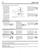
... lights or power circuits, or where it checked by the Rear Projection Television manufacturer as when going on a ? This will often require extensive work by TV stations and cable companies, as well as to provide some Rear Projection Televisions to the point of cable entry as improper adjustment of the National...
... lights or power circuits, or where it checked by the Rear Projection Television manufacturer as when going on a ? This will often require extensive work by TV stations and cable companies, as well as to provide some Rear Projection Televisions to the point of cable entry as improper adjustment of the National...
Owners Guide
Page 5
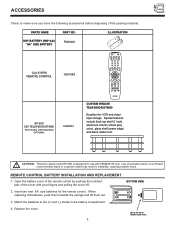
...cover of the remote control by pushing the notched part of the cover with 55DMX01W only. Lift up on tab to make sure you have the following accessories before disposing of a smaller stand, a non Hitachi recommended stand or a generic stand may result in the battery compartment. 4. ... cover. 5 ILLUSTRATION DRY BATTERY (R6P-AA) "AA" SIZE BATTERY FQ00021 CLU-579TSI REMOTE CONTROL HL01329 POWER TV DVD VCR CBL SOURCE WIZARD AV1 AV2 SAT AV3 1 2 3 4 5 6 7 8 9 SLEEP INPUT TV/PC 0 LAST CH HELP ASPECT C.S. PARTS NAME PART NO. Insert two new AA size batteries for the ...
...cover of the remote control by pushing the notched part of the cover with 55DMX01W only. Lift up on tab to make sure you have the following accessories before disposing of a smaller stand, a non Hitachi recommended stand or a generic stand may result in the battery compartment. 4. ... cover. 5 ILLUSTRATION DRY BATTERY (R6P-AA) "AA" SIZE BATTERY FQ00021 CLU-579TSI REMOTE CONTROL HL01329 POWER TV DVD VCR CBL SOURCE WIZARD AV1 AV2 SAT AV3 1 2 3 4 5 6 7 8 9 SLEEP INPUT TV/PC 0 LAST CH HELP ASPECT C.S. PARTS NAME PART NO. Insert two new AA size batteries for the ...

Owners Guide
Page 6
... to circumstances.) 6 Picture is recommended that the location selected allows a free flow of air to and from the perforated back cover of the HITACHI Rear Projection Television is under -scanning in SVGA mode. When blinking is slow, your set is ready to accept remote commands. 12 Please do...mode This set your PC to SVGA mode. HOW TO SET UP YOUR NEW HITACHI DLPTM REAR PROJECTION TV ANTENNA Unless your Rear Projection TV is connected to a cable TV system or to a centralized antenna system, a good outdoor color TV antenna is changed. However, if you are located in the room to find...
... to circumstances.) 6 Picture is recommended that the location selected allows a free flow of air to and from the perforated back cover of the HITACHI Rear Projection Television is under -scanning in SVGA mode. When blinking is slow, your set is ready to accept remote commands. 12 Please do...mode This set your PC to SVGA mode. HOW TO SET UP YOUR NEW HITACHI DLPTM REAR PROJECTION TV ANTENNA Unless your Rear Projection TV is connected to a cable TV system or to a centralized antenna system, a good outdoor color TV antenna is changed. However, if you are located in the room to find...

Owners Guide
Page 7
...ANT A/ANT B Antenna To outdoor antenna or CATV system Antenna mixer ANTENNA CONNECTIONS TO REAR JACK PANEL VHF (75-Ohm) antenna/CATV (Cable TV) When using a 300-Ohm twin lead from an outdoor antenna, connect the VHF or UHF antenna leads to screws of common connectors. Optical ...Television s rear jack panel and front control panel. Cables can be used to connect from most stores that have a second antenna or cable TV system, connect the coaxial cable to the ANT B terminal. HOOK-UP CABLES AND CONNECTORS Most video/audio connections between components can be made with...
...ANT A/ANT B Antenna To outdoor antenna or CATV system Antenna mixer ANTENNA CONNECTIONS TO REAR JACK PANEL VHF (75-Ohm) antenna/CATV (Cable TV) When using a 300-Ohm twin lead from an outdoor antenna, connect the VHF or UHF antenna leads to screws of common connectors. Optical ...Television s rear jack panel and front control panel. Cables can be used to connect from most stores that have a second antenna or cable TV system, connect the coaxial cable to the ANT B terminal. HOOK-UP CABLES AND CONNECTORS Most video/audio connections between components can be made with...
Owners Guide
Page 8
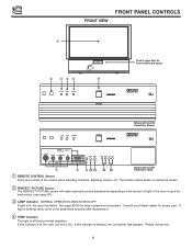
... lit, the lamp has failed. DLP A TEXAS INSTRUMENTS TECHNOLOGY LAMP TEMP POWER POWER Shown with Control Panel Door Open. ቢ REMOTE CONTROL Sensor Point your Hitachi dealer for lamp replacement procedure. DLP A TEXAS INSTRUMENTS TECHNOLOGY S-VIDEO AUDIO/ PC AUDIO INPUT 2 VIDEO L/(MONO) R INPUT 3 54321 10 9 8 7 6 15 14 13 12 11 INPUT...
... lit, the lamp has failed. DLP A TEXAS INSTRUMENTS TECHNOLOGY LAMP TEMP POWER POWER Shown with Control Panel Door Open. ቢ REMOTE CONTROL Sensor Point your Hitachi dealer for lamp replacement procedure. DLP A TEXAS INSTRUMENTS TECHNOLOGY S-VIDEO AUDIO/ PC AUDIO INPUT 2 VIDEO L/(MONO) R INPUT 3 54321 10 9 8 7 6 15 14 13 12 11 INPUT...
Owners Guide
Page 9
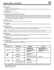
... the LAMP, TEMP, and POWER LED are blinking in the order below, the Rear Projection Television is shown in the top right corner of the TV screen. Light Blinking Slowly (2 seconds): Rear Projection Television lamp is shown in the top right corner of the screen. ቫ INPUT/EXIT Button Press ...serve as the SELECT button when in MENU mode. ቯ CHANNEL Selector Press these audio/video jacks for PC2 audio when a PC is on the TV screen. INDICATOR LAMP LED INDICATION LIGHT ON BLINKING MEANING NO LAMP LIGHT or BROKEN LAMP WRONG LAMP UNIT ASSEMBLY ACTION Need to your favorite show...
... the LAMP, TEMP, and POWER LED are blinking in the order below, the Rear Projection Television is shown in the top right corner of the TV screen. Light Blinking Slowly (2 seconds): Rear Projection Television lamp is shown in the top right corner of the screen. ቫ INPUT/EXIT Button Press ...serve as the SELECT button when in MENU mode. ቯ CHANNEL Selector Press these audio/video jacks for PC2 audio when a PC is on the TV screen. INDICATOR LAMP LED INDICATION LIGHT ON BLINKING MEANING NO LAMP LIGHT or BROKEN LAMP WRONG LAMP UNIT ASSEMBLY ACTION Need to your favorite show...

Owners Guide
Page 10
... 3 54321 10 9 8 7 6 15 14 13 12 11 PC2 INPUT MENU VOL- If the optional AESP model G301/U Macintosh to front panel jacks. CH+ TV/PC EXIT SELECT ̇̈ S-VIDEO VIDEO AUDIO IN VIDEO 3/PC2 L/(MONO) R VIDEO 3 54321 10 9 8 7 6 15 14 13 12 11 PC2 INPUT...8 9 10 1 4 5 8 910 OFF 10 VOL+ CH- FRONT PANEL JACKS AND CONNECTIONS The front panel jacks are provided as shown in , the Macintosh is connected. CH+ TV/PC EXIT SELECT ̇̈ A/V Cable and S-INPUT Cable (Optional) Audio Cable (Optional) D-SUB 15 Pin RGB Cable (Optional) S-VIDEO V L R OUTPUT Back of the standard...
... 3 54321 10 9 8 7 6 15 14 13 12 11 PC2 INPUT MENU VOL- If the optional AESP model G301/U Macintosh to front panel jacks. CH+ TV/PC EXIT SELECT ̇̈ S-VIDEO VIDEO AUDIO IN VIDEO 3/PC2 L/(MONO) R VIDEO 3 54321 10 9 8 7 6 15 14 13 12 11 PC2 INPUT...8 9 10 1 4 5 8 910 OFF 10 VOL+ CH- FRONT PANEL JACKS AND CONNECTIONS The front panel jacks are provided as shown in , the Macintosh is connected. CH+ TV/PC EXIT SELECT ̇̈ A/V Cable and S-INPUT Cable (Optional) Audio Cable (Optional) D-SUB 15 Pin RGB Cable (Optional) S-VIDEO V L R OUTPUT Back of the standard...

Owners Guide
Page 11
.... (see page 66) ቦ Optical Input This jack provides high quality audio input from a Dolby Digital DVD player or HDTV Set Top Box. NOTE: This TV s optical digital input jack fully complies with the international standard governing this connection, the audio can be compatible with 8-Ohm impedance only. ብ Coaxial Input... controlled by the television s main volume. With this type of which are used for the surround sound feature. Use a digital optical cable to connect your TV to connect external speakers, which is controlled by the television s main volume.
.... (see page 66) ቦ Optical Input This jack provides high quality audio input from a Dolby Digital DVD player or HDTV Set Top Box. NOTE: This TV s optical digital input jack fully complies with the international standard governing this connection, the audio can be compatible with 8-Ohm impedance only. ብ Coaxial Input... controlled by the television s main volume. With this type of which are used for the surround sound feature. Use a digital optical cable to connect your TV to connect external speakers, which is controlled by the television s main volume.

Owners Guide
Page 12
...; MONITOR OUT These jacks provide fixed audio and video signals which are used for connecting equipment with this case, connect the components B-Y output to the TV s PB input and the components R-Y output to INPUT 1, 2. There is no copyright infringement, the MONITOR OUT output will step through each signal source input each... time it is of these may use VIDEO, S-VIDEO, or COMPONENT: Y-PBPR Inputs to connect to the TV s PR input. NOTE: S-VIDEO Output may be labeled Y, B-Y, and R-Y.
...; MONITOR OUT These jacks provide fixed audio and video signals which are used for connecting equipment with this case, connect the components B-Y output to the TV s PB input and the components R-Y output to INPUT 1, 2. There is no copyright infringement, the MONITOR OUT output will step through each signal source input each... time it is of these may use VIDEO, S-VIDEO, or COMPONENT: Y-PBPR Inputs to connect to the TV s PR input. NOTE: S-VIDEO Output may be labeled Y, B-Y, and R-Y.

Owners Guide
Page 13
that have this case, connect the components B-Y output to the TV s PB input and the components R-Y output to the TV s PR input. In this feature. A single VCR can be used for high performance components, such as DVD players. You may be necessary to adjust TINT ... for VCR#1 and VCR#2, but note that a VCR cannot record its own video or line output. (INPUT 1 in example on page 14) Refer to the TV s Left and Right audio input jacks. Refer to obtain optimum picture quality when using the Y-PBPR jacks. 13 It may use VIDEO, S-VIDEO, or COMPONENT...
that have this case, connect the components B-Y output to the TV s PB input and the components R-Y output to the TV s PR input. In this feature. A single VCR can be used for high performance components, such as DVD players. You may be necessary to adjust TINT ... for VCR#1 and VCR#2, but note that a VCR cannot record its own video or line output. (INPUT 1 in example on page 14) Refer to the TV s Left and Right audio input jacks. Refer to obtain optimum picture quality when using the Y-PBPR jacks. 13 It may use VIDEO, S-VIDEO, or COMPONENT...

Owners Guide
Page 14
... 8 7 6 15 14 13 12 11 PC RGB INPUT 1 OPTIONAL Optional, see tips on page 13 AUDIO OUT ANT A TO CONVERTER ANT B OUTPUT INPUT Cable TV Box Stereo System Amplifier Optional, see tips on page 17 - +- + VCR #1 ANT OUTPUT IN S-VIDEO V L R OR DVD Player OUTPUT Y PB/CB PR/... R INPUT Sub Woofer LR INPUT SUB WOOFER L R AUDIO TO HI-FI + - Follow connections that pertain to each input jack. 2. Outside antenna or cable TV coaxial cable 2-Way signal splitter REAR PANEL JACKS TYPICAL FULL-FEATURE SETUP Surround Speakers L R See connections on page 13 S-VIDEO V L R OR OUTPUT Y PB ...
... 8 7 6 15 14 13 12 11 PC RGB INPUT 1 OPTIONAL Optional, see tips on page 13 AUDIO OUT ANT A TO CONVERTER ANT B OUTPUT INPUT Cable TV Box Stereo System Amplifier Optional, see tips on page 17 - +- + VCR #1 ANT OUTPUT IN S-VIDEO V L R OR DVD Player OUTPUT Y PB/CB PR/... R INPUT Sub Woofer LR INPUT SUB WOOFER L R AUDIO TO HI-FI + - Follow connections that pertain to each input jack. 2. Outside antenna or cable TV coaxial cable 2-Way signal splitter REAR PANEL JACKS TYPICAL FULL-FEATURE SETUP Surround Speakers L R See connections on page 13 S-VIDEO V L R OR OUTPUT Y PB ...

Owners Guide
Page 15
... the Left Speaker. L TO EXTERNAL SPEAKER R + - CAUTION: Do not connect speakers simultaneously to the REAR SPEAKER terminal of your audio outputs or TV. + - CAUTION: Do not short speaker terminal, (do not connect a wire directly across any two terminals). Any other type may degrade the audio ...This could cause damage to original position and the wire is in place, pull the red button back to your entertainment system. PROJECTION TV SPEAKER AMPLIFIER 15 Push in the Right Speaker black button and insert the negative (-) lead wire. In the same manner, push in...
... the Left Speaker. L TO EXTERNAL SPEAKER R + - CAUTION: Do not connect speakers simultaneously to the REAR SPEAKER terminal of your audio outputs or TV. + - CAUTION: Do not short speaker terminal, (do not connect a wire directly across any two terminals). Any other type may degrade the audio ...This could cause damage to original position and the wire is in place, pull the red button back to your entertainment system. PROJECTION TV SPEAKER AMPLIFIER 15 Push in the Right Speaker black button and insert the negative (-) lead wire. In the same manner, push in...

Owners Guide
Page 16
... with the remote control, connect the system as shown below. L R + - CONNECTING EXTERNAL AUDIO SOURCES CONNECTING EXTERNAL AUDIO AMPLIFIER To control the audio level of the TV set. 16
... with the remote control, connect the system as shown below. L R + - CONNECTING EXTERNAL AUDIO SOURCES CONNECTING EXTERNAL AUDIO AMPLIFIER To control the audio level of the TV set. 16

Owners Guide
Page 17
...CLUB, SURROUND-PRO LOGIC, or SURROUND-DOLBY DIGITAL mode. ቤ These speakers are connected to a rear speaker 8-Ohm output on the TV. ቦ This sub woofer is connected to a separate audio amplifier. Use the AUDIO TO HI-FI output on only when the television ... for SURROUND functions.) ቢ The television s internal speakers. ባ The television s internal center channel speaker, which is on the TV. ብ These speakers are connected to the SUB WOOFER output on the TV. ቤ ቤ L ቦ IN L R L R R IN OUT SUB WOOFER ᕃ ᕃ STEREO SYSTEM ባ...
...CLUB, SURROUND-PRO LOGIC, or SURROUND-DOLBY DIGITAL mode. ቤ These speakers are connected to a rear speaker 8-Ohm output on the TV. ቦ This sub woofer is connected to a separate audio amplifier. Use the AUDIO TO HI-FI output on only when the television ... for SURROUND functions.) ቢ The television s internal speakers. ባ The television s internal center channel speaker, which is on the TV. ብ These speakers are connected to the SUB WOOFER output on the TV. ቤ ቤ L ቦ IN L R L R R IN OUT SUB WOOFER ᕃ ᕃ STEREO SYSTEM ባ...
Owners Guide
Page 19
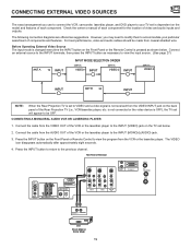
... of video and audio inputs and outputs. However, you use to connect the VCR, camcorder, laserdisc player, and DVD player to your TV set below . Press the INPUT button on the Front Panel or the Remote Control is NOT COVERED by your television warranty) COAXIAL OPTICAL ... OUT L R PC AUDIO INPUT 1 54321 10 9 8 7 6 15 14 13 12 11 PC RGB INPUT 1 ANT A TO CONVERTER ANT B VIDEO OUT AUDIO OUT VCR Hitachi Model or Similar Model 19 Connect the cable from coaxial shielded wire. The VIDEO icon disappears automatically after approximately eight seconds. 4. CONNECTING EXTERNAL VIDEO SOURCES...
... of video and audio inputs and outputs. However, you use to connect the VCR, camcorder, laserdisc player, and DVD player to your TV set below . Press the INPUT button on the Front Panel or the Remote Control is NOT COVERED by your television warranty) COAXIAL OPTICAL ... OUT L R PC AUDIO INPUT 1 54321 10 9 8 7 6 15 14 13 12 11 PC RGB INPUT 1 ANT A TO CONVERTER ANT B VIDEO OUT AUDIO OUT VCR Hitachi Model or Similar Model 19 Connect the cable from coaxial shielded wire. The VIDEO icon disappears automatically after approximately eight seconds. 4. CONNECTING EXTERNAL VIDEO SOURCES...
Owners Guide
Page 20
...is loose. 2. L R + - A single VCR can be abnormal if the connection is NOT COVERED by your VCR operating guide for more information on the TV set below. 2. Connect the cable from the VCR or laserdisc player. Press the INPUT button to the INPUT (AUDIO/L) jack. 4. SUB WOOFER L R AUDIO...the AUDIO OUT L of the VCR or the laserdisc player to view the program from the AUDIO OUT R of VCR R L V OUTPUT VCR Hitachi Model or Similar Model NOTES: 1. CONNECTING EXTERNAL VIDEO SOURCES CONNECTING A STEREO VCR OR STEREO LASERDISC PLAYER 1. The picture and sound that is played ...
...is loose. 2. L R + - A single VCR can be abnormal if the connection is NOT COVERED by your VCR operating guide for more information on the TV set below. 2. Connect the cable from the VCR or laserdisc player. Press the INPUT button to the INPUT (AUDIO/L) jack. 4. SUB WOOFER L R AUDIO...the AUDIO OUT L of the VCR or the laserdisc player to view the program from the AUDIO OUT R of VCR R L V OUTPUT VCR Hitachi Model or Similar Model NOTES: 1. CONNECTING EXTERNAL VIDEO SOURCES CONNECTING A STEREO VCR OR STEREO LASERDISC PLAYER 1. The picture and sound that is played ...
Owners Guide
Page 21
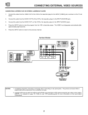
...jacks. Connect the cable from the S-VIDEO OUT of the VCR or the laserdisc player to the INPUT (S-VIDEO) jack, as shown on the TV set below. 2. Press the INPUT button to the previous channel. Connect the cable from the VCR or laserdisc player. Press the INPUT button to... return to view the program from the AUDIO OUT L of VCR or R L V S-VIDEO Laserdisc Player OUTPUT VCR or Laserdisc Player Hitachi Model or Similar Model NOTES: 1. REAR SPEAKER 8Ω ONLY STOP CONNECT ONLY 8 OHM SPEAKERS DO NOT SHORT CIRCUIT THESE TERMINALS (Such damage is loose. ...
...jacks. Connect the cable from the S-VIDEO OUT of the VCR or the laserdisc player to the INPUT (S-VIDEO) jack, as shown on the TV set below. 2. Press the INPUT button to the previous channel. Connect the cable from the VCR or laserdisc player. Press the INPUT button to... return to view the program from the AUDIO OUT L of VCR or R L V S-VIDEO Laserdisc Player OUTPUT VCR or Laserdisc Player Hitachi Model or Similar Model NOTES: 1. REAR SPEAKER 8Ω ONLY STOP CONNECT ONLY 8 OHM SPEAKERS DO NOT SHORT CIRCUIT THESE TERMINALS (Such damage is loose. ...

Owners Guide
Page 22
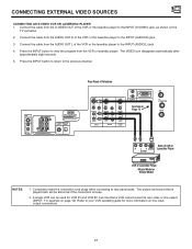
... the Y OUT of the Laserdisc/DVD player or HDTV set top box to the INPUT (Y) jack, as shown on REAR PANEL CONNECTIONS. 22 DVD Player Hitachi Model or Similar Model OUTPUT OUTPUT Back of L R Y PB PR OR AUDIO VIDEO DVD Player R L Y PB/CB PR/CR HDTV Set-Top Box Rear Panel.... 3. Connect the cable from the CB/PB OUT or B-Y OUT of Television SUB WOOFER L R AUDIO TO HI-FI + - L R + - See page 13 for tips on the TV set top box to the INPUT (PR) jack. 4.
... the Y OUT of the Laserdisc/DVD player or HDTV set top box to the INPUT (Y) jack, as shown on REAR PANEL CONNECTIONS. 22 DVD Player Hitachi Model or Similar Model OUTPUT OUTPUT Back of L R Y PB PR OR AUDIO VIDEO DVD Player R L Y PB/CB PR/CR HDTV Set-Top Box Rear Panel.... 3. Connect the cable from the CB/PB OUT or B-Y OUT of Television SUB WOOFER L R AUDIO TO HI-FI + - L R + - See page 13 for tips on the TV set top box to the INPUT (PR) jack. 4.

Owners Guide
Page 23
.... Press the INPUT button to return to select VID1-OPTICAL from the DVD player or HDTV Set Top Bx. HDTV SET-TOP BOX DVD Player Hitachi Model or Similar Model Back of SET-TOP BOX player VIDEO OUTPUT OPTICAL OUTPUT PR PB Y OR Back of DVD player VIDEO OUTPUT OPTICAL OUTPUT... to select VID2OPTICAL from the CR/PR OUT or R-Y OUT of Television SUB WOOFER L R AUDIO TO HI-FI + - See page 13 for tips on the TV set below. 2. If it is connected to INPUT 1 component jacks, make sure to the INPUT (PB) jack. 3. L R + - Connect the cable from the THEATER-INPUT SOURCE...
.... Press the INPUT button to return to select VID1-OPTICAL from the DVD player or HDTV Set Top Bx. HDTV SET-TOP BOX DVD Player Hitachi Model or Similar Model Back of SET-TOP BOX player VIDEO OUTPUT OPTICAL OUTPUT PR PB Y OR Back of DVD player VIDEO OUTPUT OPTICAL OUTPUT... to select VID2OPTICAL from the CR/PR OUT or R-Y OUT of Television SUB WOOFER L R AUDIO TO HI-FI + - See page 13 for tips on the TV set below. 2. If it is connected to INPUT 1 component jacks, make sure to the INPUT (PB) jack. 3. L R + - Connect the cable from the THEATER-INPUT SOURCE...


