
Owners Guide
Page 8
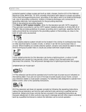
Click to see antenna grounding diagram. 16-2 Note to CATV system installer: (Only for the television set with CATV reception) This reminder is left unattended and ...
Click to see antenna grounding diagram. 16-2 Note to CATV system installer: (Only for the television set with CATV reception) This reminder is left unattended and ...
Owners Guide
Page 16
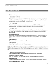
... be turned "OFF" if there is no video input when VIDEO: 1, 2 or 3 is off . 6 POWER light You will see front panel diagram. NOTE: Your HITACHI TV will make sure the TV is selected. INPUT selector Press this button to adjust your Remote at this area when selecting channels, adjusting volume...off when not in MENU mode. 4 CHANNEL selector Press these buttons for your preference, without using the remote. FRONT PANEL CONTROLS FRONT PANEL CONTROLS Click to see a red light when the TV is turned on. It makes it possible to set TV features to your desired sound level. Your selection...
... be turned "OFF" if there is no video input when VIDEO: 1, 2 or 3 is off . 6 POWER light You will see front panel diagram. NOTE: Your HITACHI TV will make sure the TV is selected. INPUT selector Press this button to adjust your Remote at this area when selecting channels, adjusting volume...off when not in MENU mode. 4 CHANNEL selector Press these buttons for your preference, without using the remote. FRONT PANEL CONTROLS FRONT PANEL CONTROLS Click to see a red light when the TV is turned on. It makes it possible to set TV features to your desired sound level. Your selection...

Owners Guide
Page 21
Follow connections that pertain to see Rear Panel Connections Illustration Typical full feature set-up. REAR PANEL CONNECTIONS REAR PANEL CONNECTIONS Click to your personal entertainment system. 21
Follow connections that pertain to see Rear Panel Connections Illustration Typical full feature set-up. REAR PANEL CONNECTIONS REAR PANEL CONNECTIONS Click to your personal entertainment system. 21

Owners Guide
Page 24
... speakers are connected to see Audio System Setup Illustration * If optional left and right speakers are connected (3), the internal speakers (1) may be heard from (2). 24 Click to a separate audio amplifier. Use the "TRANSMITTER OUT" output on the TV. 6 This sub woofer is in SURROUND DOLBY- The center channel audio will be...
... speakers are connected to see Audio System Setup Illustration * If optional left and right speakers are connected (3), the internal speakers (1) may be heard from (2). 24 Click to a separate audio amplifier. Use the "TRANSMITTER OUT" output on the TV. 6 This sub woofer is in SURROUND DOLBY- The center channel audio will be...

