
Hardware Reference Guide
Page 3
... 1-2 Removing the Access Panel and the Front Bezel 1-2 Removing Front Drive Bezels 1-5 5.25" Drive Bezel Blank 1-5 Diskette Drive Bezel 1-6 Installing Additional Memory 1-6 Installing Memory Modules 1-7 Installing an Expansion Card 1-9 Replacing or Upgrading a Drive 1-10 Drive Positions 1-11 Removing a 5.25" Drive 1-12 Removing a Diskette Drive 1-13 Removing the Lower Drive Cage 1-14 Removing a 3.5" Hard...
... 1-2 Removing the Access Panel and the Front Bezel 1-2 Removing Front Drive Bezels 1-5 5.25" Drive Bezel Blank 1-5 Diskette Drive Bezel 1-6 Installing Additional Memory 1-6 Installing Memory Modules 1-7 Installing an Expansion Card 1-9 Replacing or Upgrading a Drive 1-10 Drive Positions 1-11 Removing a 5.25" Drive 1-12 Removing a Diskette Drive 1-13 Removing the Lower Drive Cage 1-14 Removing a 3.5" Hard...

Hardware Reference Guide
Page 6
... system and turn off and that you are discharged of static electricity by briefly touching a grounded metal object. Hardware Upgrades Warnings and Cautions Before performing upgrades be sure to carefully read all of the applicable instructions, cautions, and warnings in this guide. Å WARNING:... the internal system components to cool before touching. Å WARNING: To reduce the risk of electrical shock, fire, or damage to upgrade memory or an expansion card. Before beginning these procedures, ensure that the power cord is disconnected from the power outlet 1 and the computer ...
... system and turn off and that you are discharged of static electricity by briefly touching a grounded metal object. Hardware Upgrades Warnings and Cautions Before performing upgrades be sure to carefully read all of the applicable instructions, cautions, and warnings in this guide. Å WARNING:... the internal system components to cool before touching. Å WARNING: To reduce the risk of electrical shock, fire, or damage to upgrade memory or an expansion card. Before beginning these procedures, ensure that the power cord is disconnected from the power outlet 1 and the computer ...

Hardware Reference Guide
Page 10
... remove it from the main bezel. To achieve the maximum memory support, you may be populated with industry-standard DIMMs. These memory module slots are populated with Double Data Rate-Synchronous Dynamic Random Access Memory (DDR-SDRAM) Dual Inline Memory Modules (DIMMs). Hardware Upgrades Diskette Drive Bezel Pull the right retaining tab towards the center...
... remove it from the main bezel. To achieve the maximum memory support, you may be populated with industry-standard DIMMs. These memory module slots are populated with Double Data Rate-Synchronous Dynamic Random Access Memory (DDR-SDRAM) Dual Inline Memory Modules (DIMMs). Hardware Upgrades Diskette Drive Bezel Pull the right retaining tab towards the center...

Hardware Reference Guide
Page 11
... the module. 1. Lay the computer down on . the system will be industry-standard 184-pin, unbuffered PC 2100 266 MHz-compliant CAS Latency 2 or 2.5 (CL = 2 or CL = 2.5), or PC 2700 333 MHz-compliant CAS Latency 2.5 (CL = 2.5) 2.5 volt DDR-SDRAM DIMMs. They must also contain...cord from having incompatible metals in bay 5 it easier to cool before removing the memory modules. 3. Hardware Reference Guide 1-7 Before beginning these procedures, ensure that you are not supported; Hardware Upgrades For proper system operation, if the system supports DDR-SDRAM DIMMs, the DIMMs must...
... the module. 1. Lay the computer down on . the system will be industry-standard 184-pin, unbuffered PC 2100 266 MHz-compliant CAS Latency 2 or 2.5 (CL = 2 or CL = 2.5), or PC 2700 333 MHz-compliant CAS Latency 2.5 (CL = 2.5) 2.5 volt DDR-SDRAM DIMMs. They must also contain...cord from having incompatible metals in bay 5 it easier to cool before removing the memory modules. 3. Hardware Reference Guide 1-7 Before beginning these procedures, ensure that you are not supported; Hardware Upgrades For proper system operation, if the system supports DDR-SDRAM DIMMs, the DIMMs must...

Hardware Reference Guide
Page 12
... is fully inserted and properly seated. Begin by installing a module into the socket, ensuring that you want to install. Installing a Memory Module ✎ A memory module can be installed in the closed position 3. 7. Push the module down into the socket nearest the preinstalled module, and install ...the modules following the numerical order of the memory module socket 1, and insert the memory module into the socket 2. Make sure the latches are in only one way. Open both latches of the sockets. ...
... is fully inserted and properly seated. Begin by installing a module into the socket, ensuring that you want to install. Installing a Memory Module ✎ A memory module can be installed in the closed position 3. 7. Push the module down into the socket nearest the preinstalled module, and install ...the modules following the numerical order of the memory module socket 1, and insert the memory module into the socket 2. Make sure the latches are in only one way. Open both latches of the sockets. ...

HP Compaq Business Desktop d200 Series Personal Computers Service Reference Guide, 4th Edition
Page 20
... ROMPaq diskette, which will program the system ROM with a reprogrammable flash ROM (read only memory). Left click on again to restart the computer. 3.2.2 Dual-State Power Button With Advanced Configuration...is found, you may: ■ Order an upgraded ROMPaq™ diskette from HP. ■ Download the latest ROMPaq images from http://www.hp.com/support. 3.2.1 FailSafe Boot Block ROM The ... Button section, select the desired power button setting. 3-2 336493-004 Service Reference Guide, d200 Desktop Management 3.2 ROM Flash The computer comes with a valid image. If there is valid, the...
... ROMPaq diskette, which will program the system ROM with a reprogrammable flash ROM (read only memory). Left click on again to restart the computer. 3.2.2 Dual-State Power Button With Advanced Configuration...is found, you may: ■ Order an upgraded ROMPaq™ diskette from HP. ■ Download the latest ROMPaq images from http://www.hp.com/support. 3.2.1 FailSafe Boot Block ROM The ... Button section, select the desired power button setting. 3-2 336493-004 Service Reference Guide, d200 Desktop Management 3.2 ROM Flash The computer comes with a valid image. If there is valid, the...
HP Compaq Business Desktop d200 Series Personal Computers Service Reference Guide, 4th Edition
Page 42
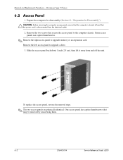
... the two screws that the power cord is turned off the unit. Some access panels use captive thumbscrews. ✎ Remove the right access panel to upgrade a drive. 3. To replace the access panel, reverse the removal steps. ✎ The two access panels are physically identical. Slide the access panel back ...access panel has captive thumbscrews that may be removed by unscrewing them. 6-2 336493-004 Service Reference Guide, d200 Remove the left access panel to upgrade memory or an expansion card. Microtower Type 2 Chassis 6.2 Access Panel 1. Removal and Replacement Procedures-
... the two screws that the power cord is turned off the unit. Some access panels use captive thumbscrews. ✎ Remove the right access panel to upgrade a drive. 3. To replace the access panel, reverse the removal steps. ✎ The two access panels are physically identical. Slide the access panel back ...access panel has captive thumbscrews that may be removed by unscrewing them. 6-2 336493-004 Service Reference Guide, d200 Remove the left access panel to upgrade memory or an expansion card. Microtower Type 2 Chassis 6.2 Access Panel 1. Removal and Replacement Procedures-
HP Compaq Business Desktop d200 Series Personal Computers Service Reference Guide, 4th Edition
Page 46
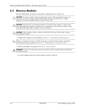
... other. Ä CAUTION: Static electricity can damage the electronic components of the contacts. When upgrading the memory, it will be careful not to work on memory used in these procedures, ensure that you are discharged of static electricity by briefly touching a ... before touching. 3. Removal and Replacement Procedures- Doing so may damage the module. 1. Microtower Type 2 Chassis 6.5 Memory Modules For more information. Ä CAUTION: When handling a memory module, be necessary to cool before removing the memory modules (Section 6.7.4, "Removing the Lower Drive Cage"). 2.
... other. Ä CAUTION: Static electricity can damage the electronic components of the contacts. When upgrading the memory, it will be careful not to work on memory used in these procedures, ensure that you are discharged of static electricity by briefly touching a ... before touching. 3. Removal and Replacement Procedures- Doing so may damage the module. 1. Microtower Type 2 Chassis 6.5 Memory Modules For more information. Ä CAUTION: When handling a memory module, be necessary to cool before removing the memory modules (Section 6.7.4, "Removing the Lower Drive Cage"). 2.
HP Compaq Business Desktop d200 Series Personal Computers Service Reference Guide, 4th Edition
Page 94
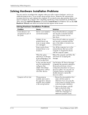
A plug and play device, you are using the correct memory modules and to determine if you must reconfigure the computer after completing installation of new external device are loose or power cables are not bent ... Manager to deselect the automatic settings for Windows XP, use Computer Setup to reconfigure or disable devices to determine possible causes. Wrong memory modules were used in the upgrade or memory modules were installed in the cable or connector are properly and securely connected and that pins in the wrong location. In Windows...
A plug and play device, you are using the correct memory modules and to determine if you must reconfigure the computer after completing installation of new external device are loose or power cables are not bent ... Manager to deselect the automatic settings for Windows XP, use Computer Setup to reconfigure or disable devices to determine possible causes. Wrong memory modules were used in the upgrade or memory modules were installed in the cable or connector are properly and securely connected and that pins in the wrong location. In Windows...


