

User Guide
Page 3
About This Guide This guide provides information on setting up the monitor, installing drivers, using the on-screen display menu, troubleshooting and technical specifications. Text set off in this manner indicates that failure to follow directions could result in this manner provides important supplemental information. ENWW iii NOTE: Text set off in this manner indicates that failure to equipment or loss of life. WARNING! CAUTION: Text set off in damage to follow directions could result in bodily harm or loss of information.
About This Guide This guide provides information on setting up the monitor, installing drivers, using the on-screen display menu, troubleshooting and technical specifications. Text set off in this manner indicates that failure to follow directions could result in this manner provides important supplemental information. ENWW iii NOTE: Text set off in this manner indicates that failure to equipment or loss of life. WARNING! CAUTION: Text set off in damage to follow directions could result in bodily harm or loss of information.
User Guide
Page 5
... Maintenance Guidelines ...2 Important Safety Information ...2 Maintenance Guidelines ...3 Cleaning the Monitor ...3 Shipping the Monitor ...3 3 Setting Up the Monitor ...4 Installing the Monitor Pedestal Base ...4 Rear Components ...5 HP ZR30w Model ...5 Routing and Connecting the Cables ...6 Connecting USB Devices ...8 Adjusting the Monitor ...8 Turning on the Monitor ...10 Removing the Monitor Pedestal Base 11 Mounting the Monitor ...12 Locating the Rating Labels ...14 Installing an...
... Maintenance Guidelines ...2 Important Safety Information ...2 Maintenance Guidelines ...3 Cleaning the Monitor ...3 Shipping the Monitor ...3 3 Setting Up the Monitor ...4 Installing the Monitor Pedestal Base ...4 Rear Components ...5 HP ZR30w Model ...5 Routing and Connecting the Cables ...6 Connecting USB Devices ...8 Adjusting the Monitor ...8 Turning on the Monitor ...10 Removing the Monitor Pedestal Base 11 Mounting the Monitor ...12 Locating the Rating Labels ...14 Installing an...
User Guide
Page 6
...A Troubleshooting ...19 Solving Common Problems ...19 Online Technical Support ...19 Preparing to Call Technical Support 19 Appendix B Technical Specifications ...21 ZR30w Model ...21 Energy Saver Feature ...22 Appendix C Agency Regulatory Notices ...23 Federal Communications Commission Notice 23 Modifications ...23 Cables ...23 ... Notices ...26 Materials Disposal ...26 Disposal of Waste Equipment by Users in Private Household in the European Union ...26 HP Recycling Program ...26 Chemical Substances ...26 Restriction of Hazardous Substances (RoHS 26 Turkey EEE Regulation ...27 Appendix D LCD...
...A Troubleshooting ...19 Solving Common Problems ...19 Online Technical Support ...19 Preparing to Call Technical Support 19 Appendix B Technical Specifications ...21 ZR30w Model ...21 Energy Saver Feature ...22 Appendix C Agency Regulatory Notices ...23 Federal Communications Commission Notice 23 Modifications ...23 Cables ...23 ... Notices ...26 Materials Disposal ...26 Disposal of Waste Equipment by Users in Private Household in the European Union ...26 HP Recycling Program ...26 Chemical Substances ...26 Restriction of Hazardous Substances (RoHS 26 Turkey EEE Regulation ...27 Appendix D LCD...
User Guide
Page 7
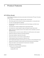
... consumption ● EDID support for Asset Management ● Compliant with the following regulated specifications: ◦ European Union CE Directives ◦ Swedish MPR II 1990 ENWW HP ZR30w Model 1 1 Product Features HP ZR30w Model The LCD (liquid crystal display) monitor has an active matrix, thin-film transistor (TFT) panel.
... consumption ● EDID support for Asset Management ● Compliant with the following regulated specifications: ◦ European Union CE Directives ◦ Swedish MPR II 1990 ENWW HP ZR30w Model 1 1 Product Features HP ZR30w Model The LCD (liquid crystal display) monitor has an active matrix, thin-film transistor (TFT) panel.

User Guide
Page 8
... If another cord is an important safety feature. • Plug the power cord in Appendix C. For your HP LCD monitor. The grounding plug is used, use with the monitor, refer to the equipment: • Do not disable the power cord grounding feature. When unplugging from the ...electrical outlet. 2 Safety and Maintenance Guidelines Important Safety Information A power cord is included with the monitor. LCD monitors that is easily accessible at http://www.hp.com/ergo and/or on or trip over . 2 Chapter 2 Safety and Maintenance Guidelines ENWW
... If another cord is an important safety feature. • Plug the power cord in Appendix C. For your HP LCD monitor. The grounding plug is used, use with the monitor, refer to the equipment: • Do not disable the power cord grounding feature. When unplugging from the ...electrical outlet. 2 Safety and Maintenance Guidelines Important Safety Information A power cord is included with the monitor. LCD monitors that is easily accessible at http://www.hp.com/ergo and/or on or trip over . 2 Chapter 2 Safety and Maintenance Guidelines ENWW

User Guide
Page 9
...properly or has been dropped or damaged, contact an authorized HP dealer, reseller, or service provider. ● Use only a power source and connection appropriate for this product yourself. Disconnect the monitor by pulling the cord. ● Turn the monitor off the monitor when not in use a 50/50 mix of water ... an outlet that you can substantially increase the life expectancy of the monitor by wiping the screen and the cabinet with a "burned-in image" are not covered under the HP warranty. ● Slots and openings in the cabinet are covered in use the damp cloth to gently wipe the...
...properly or has been dropped or damaged, contact an authorized HP dealer, reseller, or service provider. ● Use only a power source and connection appropriate for this product yourself. Disconnect the monitor by pulling the cord. ● Turn the monitor off the monitor when not in use a 50/50 mix of water ... an outlet that you can substantially increase the life expectancy of the monitor by wiping the screen and the cabinet with a "burned-in image" are not covered under the HP warranty. ● Slots and openings in the cabinet are covered in use the damp cloth to gently wipe the...

User Guide
Page 10
... Base NOTE: Be sure the pedestal base is turned off to lock the pedestal base in this occurs the screen will not recover to the monitor. When the base locks, it will be used on the panel may cause nonuniformity of color or disorientation of the LCD panel. Using both... hands, position the monitor over the pedestal base. 3 Setting Up the Monitor To set up the monitor, ensure that the power is securely locked before continuing with the setup. 4 Chapter 3 Setting Up the...
... Base NOTE: Be sure the pedestal base is turned off to lock the pedestal base in this occurs the screen will not recover to the monitor. When the base locks, it will be used on the panel may cause nonuniformity of color or disorientation of the LCD panel. Using both... hands, position the monitor over the pedestal base. 3 Setting Up the Monitor To set up the monitor, ensure that the power is securely locked before continuing with the setup. 4 Chapter 3 Setting Up the...
User Guide
Page 11
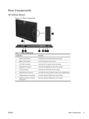
... optional USB devices to a host USB port/hub. Connects the monitor USB hub cable to the monitor. ENWW Rear Components 5 Connects the AC power cord to the monitor. Connects optional USB devices to the monitor. Turns off all power to the monitor. Rear Components HP ZR30w Model Figure 3-2 Rear Components Table 3-1 Rear Components Component 1 Cable Lock Provision...
... optional USB devices to a host USB port/hub. Connects the monitor USB hub cable to the monitor. ENWW Rear Components 5 Connects the AC power cord to the monitor. Connects optional USB devices to the monitor. Turns off all power to the monitor. Rear Components HP ZR30w Model Figure 3-2 Rear Components Table 3-1 Rear Components Component 1 Cable Lock Provision...

User Guide
Page 12
Place the monitor in the column (1) and replace the cable routing cover (2). Figure 3-4 Routing Cables 4. Remove the cable routing cover by pulling it straight off the front of the column. Before connecting the cables, route them through the cable routing hole in a convenient, well-ventilated location near the computer. 2. Connect a DVI-D signal cable or DisplayPort signal cable. 6 Chapter 3 Setting Up the Monitor ENWW Routing and Connecting the Cables 1. Figure 3-3 Removing the Cable Routing Cover 3.
Place the monitor in the column (1) and replace the cable routing cover (2). Figure 3-4 Routing Cables 4. Remove the cable routing cover by pulling it straight off the front of the column. Before connecting the cables, route them through the cable routing hole in a convenient, well-ventilated location near the computer. 2. Connect a DVI-D signal cable or DisplayPort signal cable. 6 Chapter 3 Setting Up the Monitor ENWW Routing and Connecting the Cables 1. Figure 3-3 Removing the Cable Routing Cover 3.

User Guide
Page 13
... not disable the power cord grounding plug. To reduce the risk of electric shock or damage to the DVI connector on the back of the monitor and the other end to the DisplayPort connector on the computer. 5. For your safety, do not place anything on a cord or cable. ...Do not pull on power cords or cables. When unplugging from the electrical outlet. NOTE: The video source is an important safety feature. The monitor will automatically determine which inputs have valid video signals. Arrange them . The grounding plug is determined by the video cable used. ENWW Routing and ...
... not disable the power cord grounding plug. To reduce the risk of electric shock or damage to the DVI connector on the back of the monitor and the other end to the DisplayPort connector on the computer. 5. For your safety, do not place anything on a cord or cable. ...Do not pull on power cords or cables. When unplugging from the electrical outlet. NOTE: The video source is an important safety feature. The monitor will automatically determine which inputs have valid video signals. Arrange them . The grounding plug is determined by the video cable used. ENWW Routing and ...

User Guide
Page 14
...rear panel that can be used to Step 5 in Routing and Connecting the Cables on the monitor. Refer to connect devices such as a digital camera, USB keyboard, or USB mouse. Tilt the monitor's panel forward or backward to set it to enable the USB 2.0 ports on page 6. Figure... 3-6 Connecting USB Devices Adjusting the Monitor 1. Figure 3-7 Tilting the Monitor 8 Chapter 3 Setting Up the Monitor ENWW NOTE: You must connect the USB hub cable from...
...rear panel that can be used to Step 5 in Routing and Connecting the Cables on the monitor. Refer to connect devices such as a digital camera, USB keyboard, or USB mouse. Tilt the monitor's panel forward or backward to set it to enable the USB 2.0 ports on page 6. Figure... 3-6 Connecting USB Devices Adjusting the Monitor 1. Figure 3-7 Tilting the Monitor 8 Chapter 3 Setting Up the Monitor ENWW NOTE: You must connect the USB hub cable from...

User Guide
Page 15
... the display head is safely positioned on the back of the column (2). Figure 3-9 Adjusting the Height ENWW Adjusting the Monitor 9 c. Guide the display head up when the monitor is parallel to the left or right for a comfortable viewing position. 2. A lock-down/release button on a stable surface. b....down on the back of the column prevents the display head from sliding up to the desired height (3). Adjust the monitor's height so that the monitor is locked in the lowest height position: a. Gently push down /release button on the display head (1). Swivel the...
... the display head is safely positioned on the back of the column (2). Figure 3-9 Adjusting the Height ENWW Adjusting the Monitor 9 c. Guide the display head up when the monitor is parallel to the left or right for a comfortable viewing position. 2. A lock-down/release button on a stable surface. b....down on the back of the column prevents the display head from sliding up to the desired height (3). Adjust the monitor's height so that the monitor is locked in the lowest height position: a. Gently push down /release button on the display head (1). Swivel the...

User Guide
Page 16
... inputs are not covered under the HP warranty. * A prolonged period of time is a condition that display the same static image on screen for an active input and uses that the master power switch on . 3. CAUTION: Burn-in image damage may occur on monitors that may occur on all LCD screens...priority input in the On position. 2. You can change the default source by pressing the Source button on the Monitor 1. Turning on the front panel. 10 Chapter 3 Setting Up the Monitor ENWW Ensure that input for a prolonged period of time.* To avoid burn-in use . Press the power ...
... inputs are not covered under the HP warranty. * A prolonged period of time is a condition that display the same static image on screen for an active input and uses that the master power switch on . 3. CAUTION: Burn-in image damage may occur on monitors that may occur on all LCD screens...priority input in the On position. 2. You can change the default source by pressing the Source button on the Monitor 1. Turning on the front panel. 10 Chapter 3 Setting Up the Monitor ENWW Ensure that input for a prolonged period of time.* To avoid burn-in use . Press the power ...

User Guide
Page 17
...fixture (purchased separately). Disconnect the signal, power, and USB cables from the Pedestal Base ENWW Removing the Monitor Pedestal Base 11 Removing the Monitor Pedestal Base You can remove the monitor panel from the pedestal base to the side (either right or left). 3. Also disconnect any USB ...cables that allows you to easily remove and replace the monitor panel to remove it from the base. Slide the Quick Release latch (1) on the pedestal base to mount the panel on the monitor display head (2) to the pedestal base. CAUTION: Before beginning to disassemble...
...fixture (purchased separately). Disconnect the signal, power, and USB cables from the Pedestal Base ENWW Removing the Monitor Pedestal Base 11 Removing the Monitor Pedestal Base You can remove the monitor panel from the pedestal base to the side (either right or left). 3. Also disconnect any USB ...cables that allows you to easily remove and replace the monitor panel to remove it from the base. Slide the Quick Release latch (1) on the pedestal base to mount the panel on the monitor display head (2) to the pedestal base. CAUTION: Before beginning to disassemble...
User Guide
Page 18
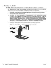
... and is intended to be used because they may damage the monitor. Figure 3-11 Removing the HP Quick Release from the pedestal base. Mounting the Monitor NOTE: This apparatus is rated to support the weight of the monitor display panel. Longer screws must not be supported by removing the... four screws. CAUTION: This monitor supports the VESA industry standard 100 mm mounting ...
... and is intended to be used because they may damage the monitor. Figure 3-11 Removing the HP Quick Release from the pedestal base. Mounting the Monitor NOTE: This apparatus is rated to support the weight of the monitor display panel. Longer screws must not be supported by removing the... four screws. CAUTION: This monitor supports the VESA industry standard 100 mm mounting ...

User Guide
Page 19
If you are mounting to a wall, HP recommends that you consult with a qualified engineering, architectural, or construction professional to determine the appropriate type and quantity of mounting fasteners required for your application ... is properly installed to lock it will make a clicking sound. Insert the monitor panel into the Quick Release ENWW Removing the Monitor Pedestal Base 13 Figure 3-13 Inserting the Monitor Panel into the Quick Release, and then press down firmly on the monitor to support applied loads. 4. Mount the Quick Release to mount the...
If you are mounting to a wall, HP recommends that you consult with a qualified engineering, architectural, or construction professional to determine the appropriate type and quantity of mounting fasteners required for your application ... is properly installed to lock it will make a clicking sound. Insert the monitor panel into the Quick Release ENWW Removing the Monitor Pedestal Base 13 Figure 3-13 Inserting the Monitor Panel into the Quick Release, and then press down firmly on the monitor to support applied loads. 4. Mount the Quick Release to mount the...

User Guide
Page 20
Figure 3-14 Locating the Rating Labels Installing an HP/Kensington MicroSaver Security Cable Lock You can secure the monitor to a fixed object with an optional cable lock available from HP. 14 Chapter 3 Setting Up the Monitor ENWW The rating labels are located on the monitor provide the spare part number, product number, and serial number. You may need these numbers when contacting HP about the monitor model. Locating the Rating Labels The rating labels on the rear panel of the monitor display head.
Figure 3-14 Locating the Rating Labels Installing an HP/Kensington MicroSaver Security Cable Lock You can secure the monitor to a fixed object with an optional cable lock available from HP. 14 Chapter 3 Setting Up the Monitor ENWW The rating labels are located on the monitor provide the spare part number, product number, and serial number. You may need these numbers when contacting HP about the monitor model. Locating the Rating Labels The rating labels on the rear panel of the monitor display head.

User Guide
Page 21
... to the graphics card. The Information File The .INF file defines monitor resources used in accordance with graphics programs to provide consistent color matching from monitor screen to printer, or from the HP monitors support Web site. ENWW Software and Utilities 15 This monitor is written in conjunction with the International Color Consortium (ICC) Profile...
... to the graphics card. The Information File The .INF file defines monitor resources used in accordance with graphics programs to provide consistent color matching from monitor screen to printer, or from the HP monitors support Web site. ENWW Software and Utilities 15 This monitor is written in conjunction with the International Color Consortium (ICC) Profile...
User Guide
Page 22
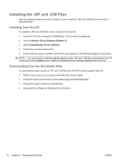
... You may need to update, you can install the .INF and .ICM files from the CD or download them. Refer to the Monitor Driver Software Readme file on -screen instructions. 5. Insert the CD in the event of .INF and .ICM files from the CD: ...and .ICM files manually from the CD in the computer CD-ROM drive. Follow the links for the monitor to http://www.hp.com/support and select the country region. 2. Installing the .INF and .ICM Files After you determine that...requirements. 4. Installing from the CD To install the .INF and .ICM files on the computer from the HP monitors support Web site: 1.
... You may need to update, you can install the .INF and .ICM files from the CD or download them. Refer to the Monitor Driver Software Readme file on -screen instructions. 5. Insert the CD in the event of .INF and .ICM files from the CD: ...and .ICM files manually from the CD in the computer CD-ROM drive. Follow the links for the monitor to http://www.hp.com/support and select the country region. 2. Installing the .INF and .ICM Files After you determine that...requirements. 4. Installing from the CD To install the .INF and .ICM files on the computer from the HP monitors support Web site: 1.

User Guide
Page 23
... (Minus) buttons at the same time enables or disables the Dynamic Contrast Ratio (DCR) function. ENWW Front Panel Controls 17 Front Panel Controls Table 4-1 Monitor Front Panel Controls Control Function 1 Source Selects the video input (DisplayPort or DVI-D) 2 - (Minus) Reduces the brightness setting. 3 + (Plus) ... flashing blue - When enabling the DCR function, the power LED will flash one time. 4 Power Turns the monitor on or off after 30 seconds) NOTE: The monitor does not support an On-Screen Display (OSD) menu. upper or lower limit of brightness control Four flashes of...
... (Minus) buttons at the same time enables or disables the Dynamic Contrast Ratio (DCR) function. ENWW Front Panel Controls 17 Front Panel Controls Table 4-1 Monitor Front Panel Controls Control Function 1 Source Selects the video input (DisplayPort or DVI-D) 2 - (Minus) Reduces the brightness setting. 3 + (Plus) ... flashing blue - When enabling the DCR function, the power LED will flash one time. 4 Power Turns the monitor on or off after 30 seconds) NOTE: The monitor does not support an On-Screen Display (OSD) menu. upper or lower limit of brightness control Four flashes of...


