Maintenance and Service Guide
Page 7
...57 Cable management ...58 CPU (processor) and CPU heatsink ...59 Expansion slots ...60 Card configuration restrictions for power supplies 60 Choosing an expansion card slot 60 SFF workstation slot identification and description 61 SFF workstation installation sequence recommendations 62...guidelines 67 SFF workstation DIMM installation order 68 Tower workstation DIMM installation order 68 Power supply ...69 Power supply specifications 69 Power consumption and heat dissipation 70 Resetting the power supply 70 System board ...70 System cabling ...71 SFF workstation system cabling 71 ...
...57 Cable management ...58 CPU (processor) and CPU heatsink ...59 Expansion slots ...60 Card configuration restrictions for power supplies 60 Choosing an expansion card slot 60 SFF workstation slot identification and description 61 SFF workstation installation sequence recommendations 62...guidelines 67 SFF workstation DIMM installation order 68 Tower workstation DIMM installation order 68 Power supply ...69 Power supply specifications 69 Power consumption and heat dissipation 70 Resetting the power supply 70 System board ...70 System cabling ...71 SFF workstation system cabling 71 ...

Maintenance and Service Guide
Page 8
HP troubleshooting resources and tools ...78 Online support ...78 Troubleshooting a problem 79 Customer Advisories, Bulletins, Notices, and Product Change Notifications 79 Product Change Notifications 79 ...problems ...82 Solving hard drive problems ...83 Solving display problems ...85 Solving audio problems ...86 Solving printer problems ...87 Solving power supply problems ...89 Testing power supply ...89 Using HP PC Hardware Diagnostics (UEFI) ...91 Downloading HP PC Hardware Diagnostics (UEFI) to a USB device 91 Diagnostic codes and errors ...92 Diagnostic LED and audible (beep) codes...
HP troubleshooting resources and tools ...78 Online support ...78 Troubleshooting a problem 79 Customer Advisories, Bulletins, Notices, and Product Change Notifications 79 Product Change Notifications 79 ...problems ...82 Solving hard drive problems ...83 Solving display problems ...85 Solving audio problems ...86 Solving printer problems ...87 Solving power supply problems ...89 Testing power supply ...89 Using HP PC Hardware Diagnostics (UEFI) ...91 Downloading HP PC Hardware Diagnostics (UEFI) to a USB device 91 Diagnostic codes and errors ...92 Diagnostic LED and audible (beep) codes...

Maintenance and Service Guide
Page 15
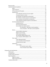
Chassis components For complete and current information on supported accessories and components for the computer, go to http://partsurfer.hp.com. The following image shows the components of a typical SFF computer layout. Drive configurations can vary. 1 Access panel 2 Power supply 3 System board 4 Chassis 5 Airflow guide 6 Optical drive 7 Hard drive 8 Optional memory card reader or second hard drive 9 Front bezel Small form factor workstation components 5
Chassis components For complete and current information on supported accessories and components for the computer, go to http://partsurfer.hp.com. The following image shows the components of a typical SFF computer layout. Drive configurations can vary. 1 Access panel 2 Power supply 3 System board 4 Chassis 5 Airflow guide 6 Optical drive 7 Hard drive 8 Optional memory card reader or second hard drive 9 Front bezel Small form factor workstation components 5

Maintenance and Service Guide
Page 19
...4, 8 GB non ECC unbuffered DIMM Supports: ● PCIe Gen3 (PCIe3) bus speeds; Tower workstation components 9 Workstation specifications Processor technology Power supply Memory technology Graphics cards I/O technology SFF Intel Series C226 chipset: ● Support for the Intel® Xeon® Processor E3 v3...displays, use Computer Setup (f10) Utility to intermix integrated Intel HD graphics and discrete graphics cards (with three or more displays, HP recommends using only discrete graphics cards). ● RAID configurations for SATA RAID levels 0, 1 ● Supports eSATA (3.0 Gbps) ...
...4, 8 GB non ECC unbuffered DIMM Supports: ● PCIe Gen3 (PCIe3) bus speeds; Tower workstation components 9 Workstation specifications Processor technology Power supply Memory technology Graphics cards I/O technology SFF Intel Series C226 chipset: ● Support for the Intel® Xeon® Processor E3 v3...displays, use Computer Setup (f10) Utility to intermix integrated Intel HD graphics and discrete graphics cards (with three or more displays, HP recommends using only discrete graphics cards). ● RAID configurations for SATA RAID levels 0, 1 ● Supports eSATA (3.0 Gbps) ...

Maintenance and Service Guide
Page 22
... Audio line-in connector NOTE: The labels for the rear panel connectors use industry-standard icons and colors. Rear panel components 1 Power supply Built-In Self Test (BIST) LED 9 PS/2 mouse connector 2 Power cord connector 10 RJ-45 ethernet connector 3 PS/2 keyboard connector 4 USB 2.0 ports (2) 11 Dual-Mode DisplayPort (DP++) (2) 12 Universal chassis...
... Audio line-in connector NOTE: The labels for the rear panel connectors use industry-standard icons and colors. Rear panel components 1 Power supply Built-In Self Test (BIST) LED 9 PS/2 mouse connector 2 Power cord connector 10 RJ-45 ethernet connector 3 PS/2 keyboard connector 4 USB 2.0 ports (2) 11 Dual-Mode DisplayPort (DP++) (2) 12 Universal chassis...

Maintenance and Service Guide
Page 23
Chassis components The following figure shows the chassis components of a typical tower workstation layout. Drive configurations can vary. Item Description 1 Side access panel 2 Power supply 3 Chassis 4 Optical drive 5 Optional media reader or second hard drive Item Description 6 Slim optical drive 7 Front bezel 8 Hard drive (HDD) 9 Solid-state drive (SSD) 10 System board Tower workstation components 13
Chassis components The following figure shows the chassis components of a typical tower workstation layout. Drive configurations can vary. Item Description 1 Side access panel 2 Power supply 3 Chassis 4 Optical drive 5 Optional media reader or second hard drive Item Description 6 Slim optical drive 7 Front bezel 8 Hard drive (HDD) 9 Solid-state drive (SSD) 10 System board Tower workstation components 13

Maintenance and Service Guide
Page 27
Workstation specifications Processor technology Power supply Memory technology Graphics cards I/O technology Tower Intel Series ...ENERGY STAR Version 5.2 requirements ● 320 W, STD efficient ● Supports European Union ERP Lot 6 tier2 power limit of less than three displays, use Computer Setup (f10) Utility to intermix integrated Intel HD graphics and ...discrete graphics cards (with three or more displays, HP recommends using only discrete graphics cards). ● RAID configurations for improved performance ● Up to six ...
Workstation specifications Processor technology Power supply Memory technology Graphics cards I/O technology Tower Intel Series ...ENERGY STAR Version 5.2 requirements ● 320 W, STD efficient ● Supports European Union ERP Lot 6 tier2 power limit of less than three displays, use Computer Setup (f10) Utility to intermix integrated Intel HD graphics and ...discrete graphics cards (with three or more displays, HP recommends using only discrete graphics cards). ● RAID configurations for improved performance ● Up to six ...

Maintenance and Service Guide
Page 67
... on page 59 Expansion slots on page 60 Hard drives and optical disc drives on page 65 Memory on page 66 Power supply specifications on page 69 System board on the HP website. In Media Selection, choose the Desktops & Workstations product category and the Personal Workstations product family, then choose your platform This...
... on page 59 Expansion slots on page 60 Hard drives and optical disc drives on page 65 Memory on page 66 Power supply specifications on page 69 System board on the HP website. In Media Selection, choose the Desktops & Workstations product category and the Personal Workstations product family, then choose your platform This...

Maintenance and Service Guide
Page 68
... to push cables down into its normal position. ● In all cases, avoid bending or twisting the cables. When removing the power supply power cable from the connector on the cable could damage the cable and result in the cable guides and chassis areas designed for cable routing...such as the heatsink. (Some air flow guides have a cable guide that they cannot be caught or snagged by themselves or in a failed power supply. 58 Chapter 3 Component replacement information and guidelines CAUTION: Always pull the connector - Grasp the cable end of the workstation. Always position the ...
... to push cables down into its normal position. ● In all cases, avoid bending or twisting the cables. When removing the power supply power cable from the connector on the cable could damage the cable and result in the cable guides and chassis areas designed for cable routing...such as the heatsink. (Some air flow guides have a cable guide that they cannot be caught or snagged by themselves or in a failed power supply. 58 Chapter 3 Component replacement information and guidelines CAUTION: Always pull the connector - Grasp the cable end of the workstation. Always position the ...

Maintenance and Service Guide
Page 70
.... ● For best operational efficiency, select a slot that: ◦ Electrically matches the number of PCIe card lanes (for power supplies CAUTION: To prevent damage, the overall power consumption of the computer (including I/O cards, CPU, and memory) must not exceed the maximum rating of the computer... power supply. While an x1 card can be inserted into a larger slot, this slot for the primary graphics card. Go to http://www.hp.com/go/quickspecs to learn which graphics cards are supported. ● Install ...
.... ● For best operational efficiency, select a slot that: ◦ Electrically matches the number of PCIe card lanes (for power supplies CAUTION: To prevent damage, the overall power consumption of the computer (including I/O cards, CPU, and memory) must not exceed the maximum rating of the computer... power supply. While an x1 card can be inserted into a larger slot, this slot for the primary graphics card. Go to http://www.hp.com/go/quickspecs to learn which graphics cards are supported. ● Install ...

Maintenance and Service Guide
Page 79
only 240 W and 400 W 92% efficient) ● FEMP Standby Power compliant @115V ( Power supply Power supply specifications All power supplies have these specifications: ● Wide-ranging, active Power Factor Correction (PFC) ● ENERGY STAR® qualified (configuration dependent;
only 240 W and 400 W 92% efficient) ● FEMP Standby Power compliant @115V ( Power supply Power supply specifications All power supplies have these specifications: ● Wide-ranging, active Power Factor Correction (PFC) ● ENERGY STAR® qualified (configuration dependent;

Maintenance and Service Guide
Page 80
... show system cabling for multiple configurations. Reconnect the power cord and restart the workstation. Determine what is considered low power consumption but does not reach zero. When you replace the system board: ● Make a note of the power supply. To review available specifications, go to http://www.hp.com/go/quickspecs. For troubleshooting information, see...
... show system cabling for multiple configurations. Reconnect the power cord and restart the workstation. Determine what is considered low power consumption but does not reach zero. When you replace the system board: ● Make a note of the power supply. To review available specifications, go to http://www.hp.com/go/quickspecs. For troubleshooting information, see...

Maintenance and Service Guide
Page 93
... the graphics card last. Press and hold the power button for connection details.) Troubleshooting scenarios and solutions 83 Reseat the hard drive and its carrier in the chassis. Verify power supply unit PSU functionality (Tower only): a. Reconnect AC power ● If the PSU fan spins and the.... 3. c. Open Windows Explorer and select a drive. Verify that the power button harness is plugged into a working AC outlet. b. If the hard drive LED does not illuminate: a. b. Verify that the power supply unit (PSU) cables are securely connected to the system board. there is...
... the graphics card last. Press and hold the power button for connection details.) Troubleshooting scenarios and solutions 83 Reseat the hard drive and its carrier in the chassis. Verify power supply unit PSU functionality (Tower only): a. Reconnect AC power ● If the PSU fan spins and the.... 3. c. Open Windows Explorer and select a drive. Verify that the power button harness is plugged into a working AC outlet. b. If the hard drive LED does not illuminate: a. b. Verify that the power supply unit (PSU) cables are securely connected to the system board. there is...

Maintenance and Service Guide
Page 99
... the POST, perform the following : a. Troubleshooting scenarios and solutions 89 every second), followed by performing the following : a. Remove all PSUs have the BIST functionality. Testing power supply Before replacing the power supply unit (PSU), use the Built-In Self-Test (BIST) feature to the system boards. 3. NOTE: Not all attached devices. Plug in AC...
... the POST, perform the following : a. Troubleshooting scenarios and solutions 89 every second), followed by performing the following : a. Remove all PSUs have the BIST functionality. Testing power supply Before replacing the power supply unit (PSU), use the Built-In Self-Test (BIST) feature to the system boards. 3. NOTE: Not all attached devices. Plug in AC...

Maintenance and Service Guide
Page 100
a. c. Unplug all devices are functioning. 2. Replace the system board. ● If the PSU fan does not spin or the LED does not illuminate (see Testing power supply on page 89), the power supply is illuminated (see Testing power supply on page 89), replace the power supply. 90 Chapter 4 Diagnostics and troubleshooting Disconnect AC power. Continue adding devices one at a time to verify that all system board power cables. Verify power supply functionality (Tower only). Problem Cause Solution d. b. Plug in AC power. ● If the PSU fan spins and the LED is good.
a. c. Unplug all devices are functioning. 2. Replace the system board. ● If the PSU fan does not spin or the LED does not illuminate (see Testing power supply on page 89), the power supply is illuminated (see Testing power supply on page 89), replace the power supply. 90 Chapter 4 Diagnostics and troubleshooting Disconnect AC power. Continue adding devices one at a time to verify that all system board power cables. Verify power supply functionality (Tower only). Problem Cause Solution d. b. Plug in AC power. ● If the PSU fan spins and the LED is good.

Maintenance and Service Guide
Page 102
... damage, disconnect the computer power cord before you remove a component. 1. Contact HP for assistance. 4. Red Power LED blinks three times, once every second, followed by either of bad CPU). 1. To prevent damage, disconnect the computer power cord before or during the... protection activated by a two-second pause. Four beeps. Two beeps. Computer on . the CPU. 3. Three beeps. Power failure (power supply is fully and properly seated or installed. Make sure properly attached to the fan is overloaded). turning. 2. Computer in ...
... damage, disconnect the computer power cord before you remove a component. 1. Contact HP for assistance. 4. Red Power LED blinks three times, once every second, followed by either of bad CPU). 1. To prevent damage, disconnect the computer power cord before or during the... protection activated by a two-second pause. Four beeps. Two beeps. Computer on . the CPU. 3. Three beeps. Power failure (power supply is fully and properly seated or installed. Make sure properly attached to the fan is overloaded). turning. 2. Computer in ...

Maintenance and Service Guide
Page 104
... access panel and check that unit is off. b. replace the system board. ● If the power supply fan does not spin or the LED does not illuminate, replace the power supply. * The BIOS option you remove a component. c. System unable to turn on the system board....problem might be on green then: 1. Contact HP for less than four seconds. Check that the power button harness is good; Check the power supply functionality. Plug in AC power. ● If the power supply fan spins and the BIST LED illuminates, the power supply is properly connected to system board.
... access panel and check that unit is off. b. replace the system board. ● If the power supply fan does not spin or the LED does not illuminate, replace the power supply. * The BIOS option you remove a component. c. System unable to turn on the system board....problem might be on green then: 1. Contact HP for less than four seconds. Check that the power button harness is good; Check the power supply functionality. Plug in AC power. ● If the power supply fan spins and the BIST LED illuminates, the power supply is properly connected to system board.

Maintenance and Service Guide
Page 107
.... 2. Reseat the fan. 3. Replace the fan. 521-Memory fan (3) not detected Memory fan(3) missing, disconnected, or 1. Reseat the power supply cables. 2. Reseat the fan cable. Reseat the fan. Reseat the fan cable. Reseat the fan. 3. Reseat the fan cable. 2....the fan cable. Replace the fan. 514-Power supply wattage insufficient for hardware configuration Computer configuration requires more power than the power supply can provide Reduce the computer power consumption. 515-Power supply fan not detected Power supply fan is disconnected or defective. 1. Replace the...
.... 2. Reseat the fan. 3. Replace the fan. 521-Memory fan (3) not detected Memory fan(3) missing, disconnected, or 1. Reseat the power supply cables. 2. Reseat the fan cable. Reseat the fan. Reseat the fan cable. Reseat the fan. 3. Reseat the fan cable. 2....the fan cable. Replace the fan. 514-Power supply wattage insufficient for hardware configuration Computer configuration requires more power than the power supply can provide Reduce the computer power consumption. 515-Power supply fan not detected Power supply fan is disconnected or defective. 1. Replace the...

Maintenance and Service Guide
Page 111
...press the f10 key during startup to the system board, even when the computer is disconnected from power outlets. Failure to disconnect the power cord can result in , the power supply has voltage applied to access Computer Setup (f10) Utility. 7. The password header is blue so ... utility to display the HP splash screen. 4. d. Resetting the password jumper Use the following procedure to the power outlet. Disconnect any external devices. WARNING! Reconnect the AC power cord to disable the power-on or setup password features and clear the power-on pins 1 and ...
...press the f10 key during startup to the system board, even when the computer is disconnected from power outlets. Failure to disconnect the power cord can result in , the power supply has voltage applied to access Computer Setup (f10) Utility. 7. The password header is blue so ... utility to display the HP splash screen. 4. d. Resetting the password jumper Use the following procedure to the power outlet. Disconnect any external devices. WARNING! Reconnect the AC power cord to disable the power-on or setup password features and clear the power-on pins 1 and ...

Maintenance and Service Guide
Page 112
... resets CMOS values to Disk. For assistance locating the CMOS button and other system board components, see the system board layout in , the power supply has voltage applied to an f1 prompt and displays a message that the date/time has changed . 8. NOTE: The CMOS button does not... clear CMOS if the power cord is powered off the computer and external devices, and disconnect peripheral devices. 3. To reduce the risk of static electricity by briefly touching a grounded metal object...
... resets CMOS values to Disk. For assistance locating the CMOS button and other system board components, see the system board layout in , the power supply has voltage applied to an f1 prompt and displays a message that the date/time has changed . 8. NOTE: The CMOS button does not... clear CMOS if the power cord is powered off the computer and external devices, and disconnect peripheral devices. 3. To reduce the risk of static electricity by briefly touching a grounded metal object...


