HP TouchSmart 9100 I/o Cover Part Replacement - Business PC
HP TouchSmart 9100 I/o Cover Part Replacement
View Results Below
Free HP TouchSmart 9100 manuals!
Problems with HP TouchSmart 9100?
Ask a Question
Free HP TouchSmart 9100 manuals!
Problems with HP TouchSmart 9100?
Ask a Question
Related Manual Pages


Similar Questions

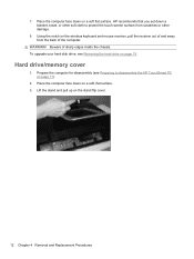
How To Remove Hard Drive Cover On 9100 Touchsmart
(Posted by jancami1 9 years ago)

Hp 8180 Removing Top Cover
need to replace a small gear . How do I remove the top of printer so I can get access to the gears.
need to replace a small gear . How do I remove the top of printer so I can get access to the gears.
(Posted by edschick 10 years ago)

Replacing The Video Card
Need instructions on how to replace the video card on my HP IQ816. I know how to take off the back ...
Need instructions on how to replace the video card on my HP IQ816. I know how to take off the back ...
(Posted by nsfw2 11 years ago)

How Do I Replace The Graphics Card In A Compaq Presario Sr5505f Desktop Computer
How do I replace the graphics card in a Compaq Presario SR5505F desktop computer?
How do I replace the graphics card in a Compaq Presario SR5505F desktop computer?
(Posted by rokluvr 12 years ago)