HP Business Desktop Products - Worldwide Limited Warranty and Technical Support (North America)
Page 3
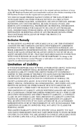
...FROM COUNTRY TO COUNTRY. www.hp.com 3 Limitation of Liability IF YOUR HP HARDWARE FAILS TO WORK AS WARRANTED ABOVE, YOUR SOLE AND EXCLUSIVE REMEDY SHALL BE REPAIR OR REPLACEMENT. YOU SHOULD MAKE PERIODIC BACKUP COPIES OF THE DATA STORED ON YOUR HARD DRIVE OR OTHER STORAGE DEVICES AS A...ANY PRIOR AGREEMENTS OR REPRESENTATIONS-INCLUDING REPRESENTATIONS MADE IN HP SALES LITERATURE OR ADVICE GIVEN TO YOU BY HP OR AN AGENT OR EMPLOYEE OF HP-THAT MAY HAVE BEEN MADE IN CONNECTION WITH YOUR PURCHASE OR LEASE OF THE HP HARDWARE. HP'S MAXIMUM LIABILITY UNDER THIS LIMITED WARRANTY IS EXPRESSLY...
...FROM COUNTRY TO COUNTRY. www.hp.com 3 Limitation of Liability IF YOUR HP HARDWARE FAILS TO WORK AS WARRANTED ABOVE, YOUR SOLE AND EXCLUSIVE REMEDY SHALL BE REPAIR OR REPLACEMENT. YOU SHOULD MAKE PERIODIC BACKUP COPIES OF THE DATA STORED ON YOUR HARD DRIVE OR OTHER STORAGE DEVICES AS A...ANY PRIOR AGREEMENTS OR REPRESENTATIONS-INCLUDING REPRESENTATIONS MADE IN HP SALES LITERATURE OR ADVICE GIVEN TO YOU BY HP OR AN AGENT OR EMPLOYEE OF HP-THAT MAY HAVE BEEN MADE IN CONNECTION WITH YOUR PURCHASE OR LEASE OF THE HP HARDWARE. HP'S MAXIMUM LIABILITY UNDER THIS LIMITED WARRANTY IS EXPRESSLY...
HP Business Desktop Products - Worldwide Limited Warranty and Technical Support (North America)
Page 5
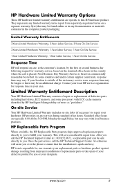
... in any limited warranty terms (apart from improper installation of replacement parts or the repair of defective parts, including hard drives, ECC memory, and some countries and under certain supplier constraints, response time may be sent directly to fulfill your area. This will assist you over the phone to this HP hardware product.
... in any limited warranty terms (apart from improper installation of replacement parts or the repair of defective parts, including hard drives, ECC memory, and some countries and under certain supplier constraints, response time may be sent directly to fulfill your area. This will assist you over the phone to this HP hardware product.

Computer Setup (F10) Utility Guide
Page 5
... a keyboard or mouse attached. Post Messages Disabled suppresses most POST messages, such as hard drives, diskette drives, optical drives, or HP Drive Keys. ■ Configure the boot priority of IDE hard drive controllers. ■ Enable Quick Boot, which allows the computer to boot the operating system when the power-on password is faster than Full Boot but does not...
... a keyboard or mouse attached. Post Messages Disabled suppresses most POST messages, such as hard drives, diskette drives, optical drives, or HP Drive Keys. ■ Configure the boot priority of IDE hard drive controllers. ■ Enable Quick Boot, which allows the computer to boot the operating system when the power-on password is faster than Full Boot but does not...

Computer Setup (F10) Utility Guide
Page 6
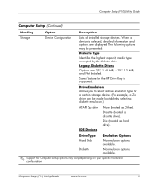
... disable removable media boot ability. ■ Enable or disable removable media write ability (when supported by hardware). ■ Solve system configuration errors detected but not automatically fixed during POST, press any key (except F1 through F12). ■ Establish an Ownership ...; Replicate your system setup by saving system configuration information on diskette and restoring it on one or more computers. ■ Configure various energy-saving features including energy saver mode, system and hard drive timeouts, power button mode, and power LED behavior. 2 www.hp.com Computer Setup...
... disable removable media boot ability. ■ Enable or disable removable media write ability (when supported by hardware). ■ Solve system configuration errors detected but not automatically fixed during POST, press any key (except F1 through F12). ■ Establish an Ownership ...; Replicate your system setup by saving system configuration information on diskette and restoring it on one or more computers. ■ Configure various energy-saving features including energy saver mode, system and hard drive timeouts, power button mode, and power LED behavior. 2 www.hp.com Computer Setup...
Computer Setup (F10) Utility Guide
Page 9
... (F10) Utility Guide www.hp.com 5 Diskette No emulation options available. ✎ Support for a certain storage device. (For example, a Zip drive can be presented: Diskette Type Identifies the highest capacity media type accepted by selecting diskette emulation.) ATAPI Zip drive None (treated as hard drive). IDE Devices Drive Type Emulation Options Hard Disk No emulation options available...
... (F10) Utility Guide www.hp.com 5 Diskette No emulation options available. ✎ Support for a certain storage device. (For example, a Zip drive can be presented: Diskette Type Identifies the highest capacity media type accepted by selecting diskette emulation.) ATAPI Zip drive None (treated as hard drive). IDE Devices Drive Type Emulation Options Hard Disk No emulation options available...

Computer Setup (F10) Utility Guide
Page 11
...hp.com 7 Logical cylinders may not exceed 256. The number of sectors per track may vary depending on , manually. Storage Options Removable Media Boot Enables/disables ability to device capabilities) are Disabled, 8, and 16. Turn the computer off, then on your specific hardware configuration. Options (subject to boot the system... from the operating system or an application) into terms the hard drive can accept. Primary IDE Controller Allows you to specify the parameters (logical cylinders...
...hp.com 7 Logical cylinders may not exceed 256. The number of sectors per track may vary depending on , manually. Storage Options Removable Media Boot Enables/disables ability to device capabilities) are Disabled, 8, and 16. Turn the computer off, then on your specific hardware configuration. Options (subject to boot the system... from the operating system or an application) into terms the hard drive can accept. Primary IDE Controller Allows you to specify the parameters (logical cylinders...
Computer Setup (F10) Utility Guide
Page 12
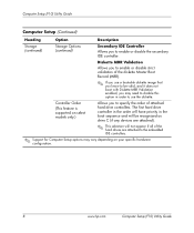
... to enable or disable the secondary IDE controller. Controller Order (This feature is supported on your specific hardware configuration. 8 www.hp.com Computer Setup (F10) Utility Guide Diskette MBR Validation Allows you to enable or disable strict validation of the diskette Master Boot... (Continued) Heading Option Description Storage (continued) Storage Options (continued) Secondary IDE Controller Allows you to specify the order of the hard drives are attached to the embedded IDE controllers. ✎ Support for Computer Setup options may need to disable this option in order to...
... to enable or disable the secondary IDE controller. Controller Order (This feature is supported on your specific hardware configuration. 8 www.hp.com Computer Setup (F10) Utility Guide Diskette MBR Validation Allows you to enable or disable strict validation of the diskette Master Boot... (Continued) Heading Option Description Storage (continued) Storage Options (continued) Secondary IDE Controller Allows you to specify the order of the hard drives are attached to the embedded IDE controllers. ✎ Support for Computer Setup options may need to disable this option in order to...

Computer Setup (F10) Utility Guide
Page 13
To boot one time from or included for consideration as a diskette drive, hard drive, optical drive, or network interface card) are checked for a bootable operating system image. Also, this password must be individually excluded from a device other than the default device specified in.... ✎ Support for more information. When POST is completed, a list of bootable devices is set in order to use some HP remote security tools. Computer Setup (F10) Utility Guide Computer Setup (Continued) Heading Option Description Storage (continued) Boot Order Allows you ...
To boot one time from or included for consideration as a diskette drive, hard drive, optical drive, or network interface card) are checked for a bootable operating system image. Also, this password must be individually excluded from a device other than the default device specified in.... ✎ Support for more information. When POST is completed, a list of bootable devices is set in order to use some HP remote security tools. Computer Setup (F10) Utility Guide Computer Setup (Continued) Heading Option Description Storage (continued) Boot Order Allows you ...

Computer Setup (F10) Utility Guide
Page 17
...system. Computer Setup (F10) Utility Guide www.hp.com 13 Computer Setup (F10) Utility Guide Computer Setup (Continued) Heading Option Description Power Energy Saver Allows you to set the energy saver mode (advanced, disable, or minimal). ✎ In the minimal energy saver mode setting, the hard drive and system...setting allows you to disable or manually select timeout values for the system and/or all attached IDE hard drives. ✎ This option does not affect power management for the ACPI-enabled operating systems. This selection will appear only if the energy saver mode is ...
...system. Computer Setup (F10) Utility Guide www.hp.com 13 Computer Setup (F10) Utility Guide Computer Setup (Continued) Heading Option Description Power Energy Saver Allows you to set the energy saver mode (advanced, disable, or minimal). ✎ In the minimal energy saver mode setting, the hard drive and system...setting allows you to disable or manually select timeout values for the system and/or all attached IDE hard drives. ✎ This option does not affect power management for the ACPI-enabled operating systems. This selection will appear only if the energy saver mode is ...

Computer Setup (F10) Utility Guide
Page 19
...select models only.) • Remote wakeup boot source (remote server/local hard drive). • After Power Loss (off power to your specific hardware configuration. Enabling this feature will cause the system to display a message before loading options ROMs. (This feature is sometimes... Management features. • UUID (Universal Unique Identifier) (enable/disable). Every HP computer has a unique identifier (serial number, date/time of manufacture, etc.). Computer Setup (F10) Utility Guide www.hp.com 15 Enabling this feature allows software (drivers, network, etc.) to read...
...select models only.) • Remote wakeup boot source (remote server/local hard drive). • After Power Loss (off power to your specific hardware configuration. Enabling this feature will cause the system to display a message before loading options ROMs. (This feature is sometimes... Management features. • UUID (Universal Unique Identifier) (enable/disable). Every HP computer has a unique identifier (serial number, date/time of manufacture, etc.). Computer Setup (F10) Utility Guide www.hp.com 15 Enabling this feature allows software (drivers, network, etc.) to read...
Hardware Reference Guide (2nd Edition)
Page 3
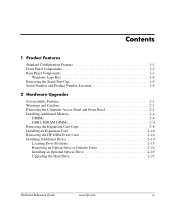
... and Front Bezel 2-2 Installing Additional Memory 2-4 DIMMs 2-4 DDR1-SDRAM DIMMs 2-4 Removing the Expansion Card Cage 2-8 Installing an Expansion Card 2-10 Removing the HP USB+Power Card 2-12 Installing Additional Drives 2-14 Locating Drive Positions 2-15 Removing an Optical Drive or Diskette Drive 2-16 Installing an Optional Optical Drive 2-19 Upgrading the Hard Drive 2-23 Hardware Reference Guide www...
... and Front Bezel 2-2 Installing Additional Memory 2-4 DIMMs 2-4 DDR1-SDRAM DIMMs 2-4 Removing the Expansion Card Cage 2-8 Installing an Expansion Card 2-10 Removing the HP USB+Power Card 2-12 Installing Additional Drives 2-14 Locating Drive Positions 2-15 Removing an Optical Drive or Diskette Drive 2-16 Installing an Optional Optical Drive 2-19 Upgrading the Hard Drive 2-23 Hardware Reference Guide www...

Hardware Reference Guide (2nd Edition)
Page 4
Contents A Specifications B Powered Serial Port Configuration C Hard Drive Installation Guidelines Using the Cable-Select Feature with Ultra ATA Devices C-1 Guidelines for Installing Ultra ATA Devices C-1 D Battery Replacement E Security Lock Provisions Installing a Security Lock E-1 F Electrostatic Discharge Preventing Electrostatic Damage F-1 Grounding Methods F-1 G Routine Computer Care and Shipping Preparation Routine Computer Care G-1 Optical Drive Precautions G-2 Operation G-2 Cleaning G-2 Safety G-2 Shipping Preparation G-3 Index iv www.hp.com Hardware Reference Guide
Contents A Specifications B Powered Serial Port Configuration C Hard Drive Installation Guidelines Using the Cable-Select Feature with Ultra ATA Devices C-1 Guidelines for Installing Ultra ATA Devices C-1 D Battery Replacement E Security Lock Provisions Installing a Security Lock E-1 F Electrostatic Discharge Preventing Electrostatic Damage F-1 Grounding Methods F-1 G Routine Computer Care and Shipping Preparation Routine Computer Care G-1 Optical Drive Precautions G-2 Operation G-2 Cleaning G-2 Safety G-2 Shipping Preparation G-3 Index iv www.hp.com Hardware Reference Guide

Hardware Reference Guide (2nd Edition)
Page 6
Front Panel Components 1 Diskette Drive Activity Light (optional) 2 Diskette Drive (optional) 3 Diskette Eject Button (optional) 4 Optical Drive (optional, CD-ROM or DVD-ROM) 5 Hard Drive Activity Light 6 Power On Light 7 Power Button 8 Optical Drive Activity Light (optional) 9 Optical Drive Eject Button (optional) 1-2 www.hp.com Hardware Reference Guide Product Features Front Panel Components Drive configuration may vary by model.
Front Panel Components 1 Diskette Drive Activity Light (optional) 2 Diskette Drive (optional) 3 Diskette Eject Button (optional) 4 Optical Drive (optional, CD-ROM or DVD-ROM) 5 Hard Drive Activity Light 6 Power On Light 7 Power Button 8 Optical Drive Activity Light (optional) 9 Optical Drive Eject Button (optional) 1-2 www.hp.com Hardware Reference Guide Product Features Front Panel Components Drive configuration may vary by model.

Hardware Reference Guide (2nd Edition)
Page 24
... M3 metric screws. While handling a drive, avoid touching the connector. Hardware Upgrades Installing Additional Drives The computer has two external drive bays. All other drives use excessive force when inserting a drive. ■ Avoid exposing a hard drive to the computer or drive: ■ If you are inserting or removing a hard drive, shut down the operating system properly, then turn off the computer...
... M3 metric screws. While handling a drive, avoid touching the connector. Hardware Upgrades Installing Additional Drives The computer has two external drive bays. All other drives use excessive force when inserting a drive. ■ Avoid exposing a hard drive to the computer or drive: ■ If you are inserting or removing a hard drive, shut down the operating system properly, then turn off the computer...
Hardware Reference Guide (2nd Edition)
Page 25
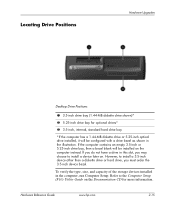
...order the 3.5-inch device bezel. If you do not have a drive in the computer, run Computer Setup. However, to install a 3.5-inch device other than a diskette drive or hard drive, you may choose to the Computer Setup (F10) Utility Guide ...on the Documentation CD for optional drives* 3 3.5-inch, internal, standard hard drive bay *If the computer has a 1.44-MB diskette drive or 5.25-inch optical drive installed, it will be configured with a drive bezel as shown in the illustration. Hardware Reference Guide www.hp...
...order the 3.5-inch device bezel. If you do not have a drive in the computer, run Computer Setup. However, to install a 3.5-inch device other than a diskette drive or hard drive, you may choose to the Computer Setup (F10) Utility Guide ...on the Documentation CD for optional drives* 3 3.5-inch, internal, standard hard drive bay *If the computer has a 1.44-MB diskette drive or 5.25-inch optical drive installed, it will be configured with a drive bezel as shown in the illustration. Hardware Reference Guide www.hp...

Hardware Reference Guide (2nd Edition)
Page 29
...To install an optional optical drive: 1. Remove the optical drive if present (see "Removing the Computer Access Panel and Front Bezel" in the lower holes on each side of the drive. Hardware Reference Guide www.hp.com 2-19 Disconnect the...drive. Ä CAUTION: Use only 3/16-inch or 5-mm long screws as guide screws. There are not enough power supply connectors to the computer. Install two M3 metric guide screws in this configuration. Hardware Upgrades Installing an Optional Optical Drive Ä CAUTION: If an optical drive is installed, you cannot install a secondary hard drive...
...To install an optional optical drive: 1. Remove the optical drive if present (see "Removing the Computer Access Panel and Front Bezel" in the lower holes on each side of the drive. Hardware Reference Guide www.hp.com 2-19 Disconnect the...drive. Ä CAUTION: Use only 3/16-inch or 5-mm long screws as guide screws. There are not enough power supply connectors to the computer. Install two M3 metric guide screws in this configuration. Hardware Upgrades Installing an Optional Optical Drive Ä CAUTION: If an optical drive is installed, you cannot install a secondary hard drive...

Hardware Reference Guide (2nd Edition)
Page 33
... from the back of the drive. Hardware Upgrades Upgrading the Hard Drive Removing and Replacing the Hard Drive The preinstalled 3.5-inch hard drive is located beneath the optical drive bay. Turn off the computer properly through the operating system, then turn off any external... devices. 3. Remove the computer access panel and front bezel (see "Removing the Computer Access Panel and Front Bezel" in this chapter). 4. To remove and replace the hard drive: 1. Disconnect the power cable and data cable from the Hard Drive Hardware Reference Guide www.hp...
... from the back of the drive. Hardware Upgrades Upgrading the Hard Drive Removing and Replacing the Hard Drive The preinstalled 3.5-inch hard drive is located beneath the optical drive bay. Turn off the computer properly through the operating system, then turn off any external... devices. 3. Remove the computer access panel and front bezel (see "Removing the Computer Access Panel and Front Bezel" in this chapter). 4. To remove and replace the hard drive: 1. Disconnect the power cable and data cable from the Hard Drive Hardware Reference Guide www.hp...

Hardware Reference Guide (2nd Edition)
Page 34
... screws. ✎ If you have installed a hard drive that is not automatically recognized by the computer, see Appendix C, "Hard Drive Installation Guidelines." 2-24 www.hp.com Hardware Reference Guide Press and hold the drive release latch 1. 7. Removing the Hard Drive To replace the hard drive, reverse the above procedure. ✎ When replacing the hard drive, transfer the four screws from the bay 3.
... screws. ✎ If you have installed a hard drive that is not automatically recognized by the computer, see Appendix C, "Hard Drive Installation Guidelines." 2-24 www.hp.com Hardware Reference Guide Press and hold the drive release latch 1. 7. Removing the Hard Drive To replace the hard drive, reverse the above procedure. ✎ When replacing the hard drive, transfer the four screws from the bay 3.

Hardware Reference Guide (2nd Edition)
Page 35
... proper air circulation to cool internal components during operation, you must install a 3.5-inch bezel. If you are installing a hard drive, you must install a diskette drive bezel. Hardware Reference Guide www.hp.com 2-25 If you are installing a diskette drive, you must install the 3.5-inch device bezel. If you are installing a 3.5-inch device other than a diskette...
... proper air circulation to cool internal components during operation, you must install a 3.5-inch bezel. If you are installing a hard drive, you must install a diskette drive bezel. Hardware Reference Guide www.hp.com 2-25 If you are installing a diskette drive, you must install the 3.5-inch device bezel. If you are installing a 3.5-inch device other than a diskette...

Hardware Reference Guide (2nd Edition)
Page 36
Guide Screw Locations To install a drive into the bay: 1. Disconnect the power cord from the power outlet and disconnect any external devices. 2. Turn off the computer properly through the operating system, then turn off any external devices. 3. Remove the computer access panel and front bezel (see "Removing the Computer Access Panel and Front Bezel" in this chapter). 2-26 www.hp.com Hardware Reference Guide Hardware Upgrades ✎ The guide screws on a 3.5-inch diskette drive 1 are placed closer together than on the hard drive 2.
Guide Screw Locations To install a drive into the bay: 1. Disconnect the power cord from the power outlet and disconnect any external devices. 2. Turn off the computer properly through the operating system, then turn off any external devices. 3. Remove the computer access panel and front bezel (see "Removing the Computer Access Panel and Front Bezel" in this chapter). 2-26 www.hp.com Hardware Reference Guide Hardware Upgrades ✎ The guide screws on a 3.5-inch diskette drive 1 are placed closer together than on the hard drive 2.


