HP Business Desktop Products - Worldwide Limited Warranty and Technical Support (North America)
Page 5
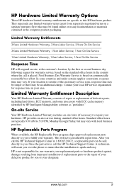
... of repair or replacement of defective parts, including hard drives, ECC memory, and some countries and under certain supplier constraints, response time may be an additional charge. After you call the HP Technical Support Center at the customer's location, by you to fulfill ... replacement parts or the repair of the customary service zone, response time may be longer or there may vary with ECC cache memory identified by HP Intelligent Manageability software as "prefailure." Limited Warranty Entitlements 3-Years Limited Hardware Warranty; 3-Years Labor Service; 3-Years On-Site Service ...
... of repair or replacement of defective parts, including hard drives, ECC memory, and some countries and under certain supplier constraints, response time may be an additional charge. After you call the HP Technical Support Center at the customer's location, by you to fulfill ... replacement parts or the repair of the customary service zone, response time may be longer or there may vary with ECC cache memory identified by HP Intelligent Manageability software as "prefailure." Limited Warranty Entitlements 3-Years Limited Hardware Warranty; 3-Years Labor Service; 3-Years On-Site Service ...

Computer Setup (F10) Utility Guide
Page 5
... or without a keyboard or mouse attached. Post Messages Disabled suppresses most POST messages, such as hard drives, diskette drives, optical drives, or HP Drive Keys. ■ Configure the boot priority of IDE hard drive controllers. ■ Enable Quick Boot, which allows the computer to 30... Setup (F10) Utility Guide Computer Setup (F10) Utilities Use the Computer Setup (F10) Utility to change , or verify the system configuration, including settings for processor, graphics, memory, audio, storage, communications, and input devices. ■ Modify the boot order of bootable devices such as...
... or without a keyboard or mouse attached. Post Messages Disabled suppresses most POST messages, such as hard drives, diskette drives, optical drives, or HP Drive Keys. ■ Configure the boot priority of IDE hard drive controllers. ■ Enable Quick Boot, which allows the computer to 30... Setup (F10) Utility Guide Computer Setup (F10) Utilities Use the Computer Setup (F10) Utility to change , or verify the system configuration, including settings for processor, graphics, memory, audio, storage, communications, and input devices. ■ Modify the boot order of bootable devices such as...

Computer Setup (F10) Utility Guide
Page 8
... Setup (F10) Utility Guide Computer Setup Heading Option Description File System Information Lists: • Product name • Processor type/speed/stepping • Cache size (L1/L2) • Installed memory size • System ROM (includes family name and version) • Chassis serial ...number • Asset tracking number • Integrated MAC address for the HP Drive Key is supported. Save/Restore for specific Computer Setup...
... Setup (F10) Utility Guide Computer Setup Heading Option Description File System Information Lists: • Product name • Processor type/speed/stepping • Cache size (L1/L2) • Installed memory size • System ROM (includes family name and version) • Chassis serial ...number • Asset tracking number • Integrated MAC address for the HP Drive Key is supported. Save/Restore for specific Computer Setup...

Computer Setup (F10) Utility Guide
Page 20
... may vary depending on your specific hardware configuration. 16 www.hp.com Computer Setup (F10) Utility Guide Enabling this feature will allow Microsoft Windows Operating Systems to disable them entirely. The advantage is that some amount of memory below 1 MB is that a popular memory manager, HIMEM.SYS, does not work properly. • ACPI/USB...
... may vary depending on your specific hardware configuration. 16 www.hp.com Computer Setup (F10) Utility Guide Enabling this feature will allow Microsoft Windows Operating Systems to disable them entirely. The advantage is that some amount of memory below 1 MB is that a popular memory manager, HIMEM.SYS, does not work properly. • ACPI/USB...

Computer Setup (F10) Utility Guide
Page 22
...specify the amount of option ROMS. ✎ Support for use by advanced users only. Allows ROM to enable or disable downloading of system memory reserved for Computer Setup options may vary depending on your graphics controller. • Monitor Tracking (enable/disable). Computer Setup (F10) ...Heading Option Description Advanced* (continued) Device Options (continued) *These options should be used by your specific hardware configuration. 18 www.hp.com Computer Setup (F10) Utility Guide Allows the mouse to set: • ACPI S3 Hard Disk Reset (enable/disable). Allows you...
...specify the amount of option ROMS. ✎ Support for use by advanced users only. Allows ROM to enable or disable downloading of system memory reserved for Computer Setup options may vary depending on your graphics controller. • Monitor Tracking (enable/disable). Computer Setup (F10) ...Heading Option Description Advanced* (continued) Device Options (continued) *These options should be used by your specific hardware configuration. 18 www.hp.com Computer Setup (F10) Utility Guide Allows the mouse to set: • ACPI S3 Hard Disk Reset (enable/disable). Allows you...
Hardware Reference Guide (2nd Edition)
Page 3
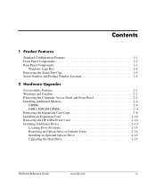
... 1-6 2 Hardware Upgrades Serviceability Features 2-1 Warnings and Cautions 2-1 Removing the Computer Access Panel and Front Bezel 2-2 Installing Additional Memory 2-4 DIMMs 2-4 DDR1-SDRAM DIMMs 2-4 Removing the Expansion Card Cage 2-8 Installing an Expansion Card 2-10 Removing the HP USB+Power Card 2-12 Installing Additional Drives 2-14 Locating Drive Positions 2-15 Removing an Optical Drive or...
... 1-6 2 Hardware Upgrades Serviceability Features 2-1 Warnings and Cautions 2-1 Removing the Computer Access Panel and Front Bezel 2-2 Installing Additional Memory 2-4 DIMMs 2-4 DDR1-SDRAM DIMMs 2-4 Removing the Expansion Card Cage 2-8 Installing an Expansion Card 2-10 Removing the HP USB+Power Card 2-12 Installing Additional Drives 2-14 Locating Drive Positions 2-15 Removing an Optical Drive or...

Hardware Reference Guide (2nd Edition)
Page 14
... ■ single-sided or double-sided DIMMS (does not support double-sided X16 DDR1 DIMMS) 2-4 www.hp.com Hardware Reference Guide DIMMs The memory sockets on the frequency of the processor front side bus. The DDR1-SDRAM DIMMs must be: ■ industry-standard 184-pin ■ ...✎ Though a PC3200 400 MHz DIMM can populate the system board with up to 2 GB of 400MHz is not supported; To achieve the maximum memory support, you can be populated with up to two industry-standard DIMMs. These memory module slots are populated with double data rate synchronous dynamic random...
... ■ single-sided or double-sided DIMMS (does not support double-sided X16 DDR1 DIMMS) 2-4 www.hp.com Hardware Reference Guide DIMMs The memory sockets on the frequency of the processor front side bus. The DDR1-SDRAM DIMMs must be: ■ industry-standard 184-pin ■ ...✎ Though a PC3200 400 MHz DIMM can populate the system board with up to 2 GB of 400MHz is not supported; To achieve the maximum memory support, you can be populated with up to two industry-standard DIMMs. These memory module slots are populated with double data rate synchronous dynamic random...

Hardware Reference Guide (2nd Edition)
Page 15
.... Hardware Upgrades ■ DIMMs constructed with x8 and x16 DDR devices with a 400 MHz processor bus, the system will run at the highest supported memory speed. Before beginning these procedures, ensure that you install unsupported DIMMs. The following processor bus frequencies are discharged of ...the computer or optional cards. Hardware Reference Guide www.hp.com 2-5 DIMM If Processor Bus Frequency is Memory Frequency is PC2100 400 MHz 266 MHz PC2100 533 MHz 266 MHz PC2700 400 MHz 266 MHz PC2700 ...
.... Hardware Upgrades ■ DIMMs constructed with x8 and x16 DDR devices with a 400 MHz processor bus, the system will run at the highest supported memory speed. Before beginning these procedures, ensure that you install unsupported DIMMs. The following processor bus frequencies are discharged of ...the computer or optional cards. Hardware Reference Guide www.hp.com 2-5 DIMM If Processor Bus Frequency is Memory Frequency is PC2100 400 MHz 266 MHz PC2100 533 MHz 266 MHz PC2700 400 MHz 266 MHz PC2700 ...

Hardware Reference Guide (2nd Edition)
Page 16
... external devices. 2. Disconnect the power cord from hot surfaces, allow the internal system components to cool before raising or lowering the Easy Access drive bay to an upright position. Locate the memory module sockets. Å WARNING: To reduce risk of the contacts. Rotating the... Check the position of all cables and wires before touching. 2-6 www.hp.com Hardware Reference Guide Doing so may damage the module. 1. Rotate the Easy Access drive bay to prevent damage. 4. Turn off the computer properly through the operating system, then turn off any external devices. 3.
... external devices. 2. Disconnect the power cord from hot surfaces, allow the internal system components to cool before raising or lowering the Easy Access drive bay to an upright position. Locate the memory module sockets. Å WARNING: To reduce risk of the contacts. Rotating the... Check the position of all cables and wires before touching. 2-6 www.hp.com Hardware Reference Guide Doing so may damage the module. 1. Rotate the Easy Access drive bay to prevent damage. 4. Turn off the computer properly through the operating system, then turn off any external devices. 3.

Hardware Reference Guide (2nd Edition)
Page 17
Hardware Upgrades 6. Installing a DIMM ✎ A memory module can be installed in the closed position 3. Match the notch on the module with the tab on the memory socket. 7. Make sure the latches are in only one way. Hardware Reference Guide www.hp.com 2-7 Open both latches of the memory module socket 1, then insert the memory module into the socket, ensuring that the module is fully inserted and properly seated. Push the module down into the socket 2.
Hardware Upgrades 6. Installing a DIMM ✎ A memory module can be installed in the closed position 3. Match the notch on the module with the tab on the memory socket. 7. Make sure the latches are in only one way. Hardware Reference Guide www.hp.com 2-7 Open both latches of the memory module socket 1, then insert the memory module into the socket, ensuring that the module is fully inserted and properly seated. Push the module down into the socket 2.

Hardware Reference Guide (2nd Edition)
Page 18
Repeat steps 6 and 7 for any additional modules that you power on the computer. The computer automatically recognizes the additional memory the next time you want to the down position. Disconnect the power cord from the power outlet and disconnect any external devices. 2. ...and Front Bezel" in the chassis when lowering the Easy Access drive bay. 10. Hardware Upgrades 8. Turn off the computer properly through the operating system, then turn off any external devices. 3. Replace the front bezel and computer access panel. Removing the Expansion Card Cage To remove the expansion card...
Repeat steps 6 and 7 for any additional modules that you power on the computer. The computer automatically recognizes the additional memory the next time you want to the down position. Disconnect the power cord from the power outlet and disconnect any external devices. 2. ...and Front Bezel" in the chassis when lowering the Easy Access drive bay. 10. Hardware Upgrades 8. Turn off the computer properly through the operating system, then turn off any external devices. 3. Replace the front bezel and computer access panel. Removing the Expansion Card Cage To remove the expansion card...

Hardware Reference Guide (2nd Edition)
Page 61
... serial port 1-5 coin cell battery type 1 D-2 type 2 D-3 components front panel 1-2 rear panel 1-3 computer care,guidelines G-1 Hardware Reference Guide Index D DIMMs (dual inline memory modules) installation 2-5 socket locations 2-5 diskette drive activity light 1-2 eject button 1-2 removing 2-16 drive installation, guidelines 2-14 drive positions 2-15 E eject button, optical drive ...panel components 1-2 G guidelines battery replacement D-1 computer care G-1 DDR-SDRAM DIMMs 2-4 drive installation 2-14 optical drive G-2 shipping preparation G-3 Ultra ATA installation C-1 www.hp.com Index-1
... serial port 1-5 coin cell battery type 1 D-2 type 2 D-3 components front panel 1-2 rear panel 1-3 computer care,guidelines G-1 Hardware Reference Guide Index D DIMMs (dual inline memory modules) installation 2-5 socket locations 2-5 diskette drive activity light 1-2 eject button 1-2 removing 2-16 drive installation, guidelines 2-14 drive positions 2-15 E eject button, optical drive ...panel components 1-2 G guidelines battery replacement D-1 computer care G-1 DDR-SDRAM DIMMs 2-4 drive installation 2-14 optical drive G-2 shipping preparation G-3 Ultra ATA installation C-1 www.hp.com Index-1

Hardware Reference Guide (2nd Edition)
Page 62
... E-1 coin cell battery (type 1) D-2 coin cell battery (type 2) D-4 expansion card 2-10 hard drive 2-28 memory 2-4 optical drive 2-19 padlock E-2 UltraATA C-1 J jumpers B-3 powered serial port B-3 serial port location B-3 standard serial port B-3 K keyboard port 1-3 L lock E-1, E-2 M memory identifying 2-7 installing 2-4 module sockets 2-4 monitor connector 1-3 mouse connector 1-3 O optical drive 1-2 activity light 1-2 ATA ... expansion card cage 2-8, 2-9 expansion slot cover 2-10 front bezel 2-3 hard drive 2-24 optical drive 2-16 serial port cap 1-5 Index-2 www.hp.com Hardware Reference Guide
... E-1 coin cell battery (type 1) D-2 coin cell battery (type 2) D-4 expansion card 2-10 hard drive 2-28 memory 2-4 optical drive 2-19 padlock E-2 UltraATA C-1 J jumpers B-3 powered serial port B-3 serial port location B-3 standard serial port B-3 K keyboard port 1-3 L lock E-1, E-2 M memory identifying 2-7 installing 2-4 module sockets 2-4 monitor connector 1-3 mouse connector 1-3 O optical drive 1-2 activity light 1-2 ATA ... expansion card cage 2-8, 2-9 expansion slot cover 2-10 front bezel 2-3 hard drive 2-24 optical drive 2-16 serial port cap 1-5 Index-2 www.hp.com Hardware Reference Guide

Hardware Reference Guide (2nd Edition)
Page 63
USB+Power card 2-12 RJ-45 connector 1-3 routine care G-1 S SDRAM (synchronous dynamic random access memory) 2-4 security lock provisions E-1 serial number location 1-6 serial port cap, removing 1-5 serial ports B-1 jumper location B-3 powered B-1 Index standard B-1 shipping preparation, guidelines G-3 socket locations, DIMM 2-5 U Ultra ATA cable-select feature C-1 installation guidelines C-1 USB+Power card 2-12 removing 2-12 W Windows Logo key 1-4 Hardware Reference Guide www.hp.com Index-3
USB+Power card 2-12 RJ-45 connector 1-3 routine care G-1 S SDRAM (synchronous dynamic random access memory) 2-4 security lock provisions E-1 serial number location 1-6 serial port cap, removing 1-5 serial ports B-1 jumper location B-3 powered B-1 Index standard B-1 shipping preparation, guidelines G-3 socket locations, DIMM 2-5 U Ultra ATA cable-select feature C-1 installation guidelines C-1 USB+Power card 2-12 removing 2-12 W Windows Logo key 1-4 Hardware Reference Guide www.hp.com Index-3

HP USB Barcode Scanner Programming Reference Guide
Page 7
... Guide 1-1 The scanner is shipped with an asterisk (*). Feature values are indicated with the default settings described in non-volatile memory and are stored in the Chapter 4, "Programming User Preferences," of the HP USB Barcode Scanner User guide. 1 Programming Your Scanner You have the option to program your scanner. The settings are...
... Guide 1-1 The scanner is shipped with an asterisk (*). Feature values are indicated with the default settings described in non-volatile memory and are stored in the Chapter 4, "Programming User Preferences," of the HP USB Barcode Scanner User guide. 1 Programming Your Scanner You have the option to program your scanner. The settings are...

Getting Started (3rd Edition)
Page 10
Canadian, and various international regulations. 6 www.hp.com Getting Started also includes basic troubleshooting information should you set up factory-provided software; Getting Started ■ Getting Started (available in print ... encounter any problems during initial startup. ■ Hardware Reference Guide (PDF on Documentation CD) Provides an overview of computers and includes information on RTC batteries, memory, and power supply. ■ Computer Setup (F10) Utility Guide (PDF on Documentation CD) Provides instructions on using network interface controller (NIC) features that...
Canadian, and various international regulations. 6 www.hp.com Getting Started also includes basic troubleshooting information should you set up factory-provided software; Getting Started ■ Getting Started (available in print ... encounter any problems during initial startup. ■ Hardware Reference Guide (PDF on Documentation CD) Provides an overview of computers and includes information on RTC batteries, memory, and power supply. ■ Computer Setup (F10) Utility Guide (PDF on Documentation CD) Provides instructions on using network interface controller (NIC) features that...

Getting Started (3rd Edition)
Page 23
...hp.com 19 Memory is installed incorrectly or is bad. 1. Wrong memory modules were used in the upgrade or memory modules were installed in the Device Manager. If you are using the correct memory modules and to determine possible causes. 3. Replace the system board. Replace third-party memory with the system...followed by a two-second pause, and the computer beeps five times. Review the documentation that came with HP memory. 4. Getting Started Solving Hardware Installation Problems (Continued) Problem Cause Solution Computer will not start. Reseat DIMMs. Power on the...
...hp.com 19 Memory is installed incorrectly or is bad. 1. Wrong memory modules were used in the upgrade or memory modules were installed in the Device Manager. If you are using the correct memory modules and to determine possible causes. 3. Replace the system board. Replace third-party memory with the system...followed by a two-second pause, and the computer beeps five times. Review the documentation that came with HP memory. 4. Getting Started Solving Hardware Installation Problems (Continued) Problem Cause Solution Computer will not start. Reseat DIMMs. Power on the...

Getting Started (3rd Edition)
Page 29
... are not supported by a two-second pause. For systems with a graphics card: 1. Reseat DIMMs. Power on the system. 2. For systems with integrated graphics, replace the system board. Power on the system. 2. Replace third-party memory with a PCI graphics card. Replace the system board. Recommended Action 1. Replace the graphics card with HP memory. 4. Getting Started Diagnostic Front Panel LEDs and...
... are not supported by a two-second pause. For systems with a graphics card: 1. Reseat DIMMs. Power on the system. 2. For systems with integrated graphics, replace the system board. Power on the system. 2. Replace third-party memory with a PCI graphics card. Replace the system board. Recommended Action 1. Replace the graphics card with HP memory. 4. Getting Started Diagnostic Front Panel LEDs and...

HP Point of Sale System rp5000 Illustrated Parts Map, 4th Edition
Page 1
...-001*⌧ 398878-001 2 Backplane (riser board without tray) 323090-001*⌧ 398778-001 3 Powered USB card 337069-001*⌧ 398879-001 Memory Modules 4 128 MB 333 MHz DDR, PC3200 + 256 MB 333 MHz DDR, PC3200 + 512 MB 333 MHz DDR, PC3200 + 1.0 GB ... etc.) restricting the use of their respective companies. HP Point of hazardous substances in electrical equipment. The information in this case either the Original Spare or the Modified Spare may be construed as the replacement part. The use of Sale System rp5000 Illustrated Parts Map Small Form Factor Chassis © ...
...-001*⌧ 398878-001 2 Backplane (riser board without tray) 323090-001*⌧ 398778-001 3 Powered USB card 337069-001*⌧ 398879-001 Memory Modules 4 128 MB 333 MHz DDR, PC3200 + 256 MB 333 MHz DDR, PC3200 + 512 MB 333 MHz DDR, PC3200 + 1.0 GB ... etc.) restricting the use of their respective companies. HP Point of hazardous substances in electrical equipment. The information in this case either the Original Spare or the Modified Spare may be construed as the replacement part. The use of Sale System rp5000 Illustrated Parts Map Small Form Factor Chassis © ...

HP Point of Sale System rp5000 Illustrated Parts Map, 4th Edition
Page 2
... 1 COM 2 CONN1 DDR 1 DDR 2 FLOPPY AGP slot (for powered USB card only) Battery CPU fan Flying serial port Main power (20 pin) Memory socket 1 Memory socket2 Diskette drive F_P 1 Front panel power switch/LED J5V_SEL 1** 5V Jumper for COM 1# J5V_SEL 2** 5V Jumper for COM 2# J5V_SEL 3** 5V Jumper...front of beeps. Turn off Power Supply failure CPU thermal shutdown CPU not installed Power supply overload ( crow bar) No memory No graphics System board failure (detected prior to Diskette Restore From Diskette Set defaults and Exit IDE DPS Self-Test Controller Order Smart Sensor DriveLock...
... 1 COM 2 CONN1 DDR 1 DDR 2 FLOPPY AGP slot (for powered USB card only) Battery CPU fan Flying serial port Main power (20 pin) Memory socket 1 Memory socket2 Diskette drive F_P 1 Front panel power switch/LED J5V_SEL 1** 5V Jumper for COM 1# J5V_SEL 2** 5V Jumper for COM 2# J5V_SEL 3** 5V Jumper...front of beeps. Turn off Power Supply failure CPU thermal shutdown CPU not installed Power supply overload ( crow bar) No memory No graphics System board failure (detected prior to Diskette Restore From Diskette Set defaults and Exit IDE DPS Self-Test Controller Order Smart Sensor DriveLock...


