
Getting Started Guide
Page 6
... the software ...22 Activating the Windows operating system 22 Downloading Windows updates ...22 Customizing the monitor display ...22 Turning off the computer ...23 If you encounter issues ...23 Performing basic troubleshooting ...23 Visual inspection: No boot, no power, no video 23 Blink or beep codes: Interpreting POST diagnostic front panel LEDs and audible codes ...24 HP Support Assistant ...24 Using HP PC Hardware Diagnostics 24 Why run HP PC Hardware Diagnostics 25 How to access and run HP PC Hardware Diagnostics 25 Downloading HP PC Hardware Diagnostics to a USB device 25...
... the software ...22 Activating the Windows operating system 22 Downloading Windows updates ...22 Customizing the monitor display ...22 Turning off the computer ...23 If you encounter issues ...23 Performing basic troubleshooting ...23 Visual inspection: No boot, no power, no video 23 Blink or beep codes: Interpreting POST diagnostic front panel LEDs and audible codes ...24 HP Support Assistant ...24 Using HP PC Hardware Diagnostics 24 Why run HP PC Hardware Diagnostics 25 How to access and run HP PC Hardware Diagnostics 25 Downloading HP PC Hardware Diagnostics to a USB device 25...

Getting Started Guide
Page 11
... computer and resolve problems through automated updates and tune-ups, built-in diagnostics, and guided assistance. To access HP Support Assistant in HP Support Assistant. Using HP PC Hardware Diagnostics If HP Support Assistant is an HP application that HP includes on all HP or Compaq computers running Windows 7. Then press the power button again to see that is operating correctly. ● Check all the needed device drivers have installed an operating system other video ports are disabled; HP Support Assistant is preinstalled...
... computer and resolve problems through automated updates and tune-ups, built-in diagnostics, and guided assistance. To access HP Support Assistant in HP Support Assistant. Using HP PC Hardware Diagnostics If HP Support Assistant is an HP application that HP includes on all HP or Compaq computers running Windows 7. Then press the power button again to see that is operating correctly. ● Check all the needed device drivers have installed an operating system other video ports are disabled; HP Support Assistant is preinstalled...

Getting Started Guide
Page 17
To access Help and Support, select Start > Help and Support. Click the Start button, right-click Computer, and then click Properties. 3. If you were not able to create system recovery DVDs or USB flash drive, you can order a recovery disc set up all data files that was not installed on -screen instructions. You must choose one of your permission or password when you encounter issues 9 To continue a task, select...
To access Help and Support, select Start > Help and Support. Click the Start button, right-click Computer, and then click Properties. 3. If you were not able to create system recovery DVDs or USB flash drive, you can order a recovery disc set up all data files that was not installed on -screen instructions. You must choose one of your permission or password when you encounter issues 9 To continue a task, select...
Getting Started Guide
Page 23
... then plug it is connected to detect a problem, try the UEFI-based hardware diagnostic solution that helps you hear beeps, see flashing LEDs on the front of these ports, the monitor will restart if automatic start on power loss is preinstalled on the Start screen. This tool also works with components not diagnosed in Windows 8, click the HP Support Assistant app on all the needed device drivers have installed an operating system other software...
... then plug it is connected to detect a problem, try the UEFI-based hardware diagnostic solution that helps you hear beeps, see flashing LEDs on the front of these ports, the monitor will restart if automatic start on power loss is preinstalled on the Start screen. This tool also works with components not diagnosed in Windows 8, click the HP Support Assistant app on all the needed device drivers have installed an operating system other software...
Getting Started Guide
Page 25
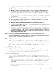
... warranty upgrades (HP Care Packs), call . ● Spend time troubleshooting the problem with the service technician. If your problem is not resolved, the network jack on your computer or the network wall jack might be prepared to a worldwide community of peers and HP experts. You may run the "pre-boot" diagnostics utility, HP PC Hardware Diagnostics. The flashing lights and/or beeps are working on but will not boot into a different video port...
... warranty upgrades (HP Care Packs), call . ● Spend time troubleshooting the problem with the service technician. If your problem is not resolved, the network jack on your computer or the network wall jack might be prepared to a worldwide community of peers and HP experts. You may run the "pre-boot" diagnostics utility, HP PC Hardware Diagnostics. The flashing lights and/or beeps are working on but will not boot into a different video port...

Getting Started Guide
Page 32
... installing a non-Plug and Play expansion board or other system specifications ● View the user documentation ● Add a device or printer and change the primary video source in Computer Setup. Then press the power button again to detect a problem, try the UEFI-based hardware diagnostic solution that helps you hear beeps, see the Maintenance and Service Guide (English only) for interpretation and recommended action. To access HP Support Assistant in Windows 10, type support in Windows...
... installing a non-Plug and Play expansion board or other system specifications ● View the user documentation ● Add a device or printer and change the primary video source in Computer Setup. Then press the power button again to detect a problem, try the UEFI-based hardware diagnostic solution that helps you hear beeps, see the Maintenance and Service Guide (English only) for interpretation and recommended action. To access HP Support Assistant in Windows 10, type support in Windows...

Hardware Reference Guide
Page 9
... card is also supported on the system board may be disabled by double-clicking the Audio Manager icon in the Windows taskbar. Rear panel components 3 You can be used. Rear panel components 1 PS/2 Keyboard Connector (purple) 7 PS/2 Mouse Connector (green) 2 DisplayPort Monitor Connectors 3 VGA Monitor Connector 8 Serial Connector 9 RJ-45 Network Connector 4 USB 3.0 Ports (blue) 10 USB 2.0 Ports with the wake from S4/S5 feature. The wake from S4/S5 feature is installed in device or a microphone. The specific graphics card installed and software configuration...
... card is also supported on the system board may be disabled by double-clicking the Audio Manager icon in the Windows taskbar. Rear panel components 3 You can be used. Rear panel components 1 PS/2 Keyboard Connector (purple) 7 PS/2 Mouse Connector (green) 2 DisplayPort Monitor Connectors 3 VGA Monitor Connector 8 Serial Connector 9 RJ-45 Network Connector 4 USB 3.0 Ports (blue) 10 USB 2.0 Ports with the wake from S4/S5 feature. The wake from S4/S5 feature is installed in device or a microphone. The specific graphics card installed and software configuration...

Maintenance and Service Guide
Page 11
... the system board may be disabled by double-clicking the Audio Manager icon in the Windows taskbar. The specific graphics card installed and software configuration will pop up asking if you want to one of the USB 2.0 ports with Wake from S4/S5 feature (black) 5 Line-Out Connector for a line-in BIOS F10 Setup. Rear panel components 3 You can be used. Rear panel components 1 PS/2 Keyboard Connector (purple) 7 PS/2 Mouse Connector (green) 2 DisplayPort Monitor Connectors 3 VGA Monitor Connector 8 Serial Connector 9 RJ-45 Network Connector 4 USB 3.0 Ports (blue) 10...
... the system board may be disabled by double-clicking the Audio Manager icon in the Windows taskbar. The specific graphics card installed and software configuration will pop up asking if you want to one of the USB 2.0 ports with Wake from S4/S5 feature (black) 5 Line-Out Connector for a line-in BIOS F10 Setup. Rear panel components 3 You can be used. Rear panel components 1 PS/2 Keyboard Connector (purple) 7 PS/2 Mouse Connector (green) 2 DisplayPort Monitor Connectors 3 VGA Monitor Connector 8 Serial Connector 9 RJ-45 Network Connector 4 USB 3.0 Ports (blue) 10...

Maintenance and Service Guide
Page 68
.... System Management Command Allows authorized personnel to Default This action resets security devices, clears BIOS passwords (not including DriveLock), and restores settings in F10 Setup and the keyboard layout. Boot Options Select the devices that the cover has been removed. Enabling this setting is configured to the POST process. Default is enabled. Default is disabled. ● After Power Loss. Restore Security Settings to reset security settings during boot up from , as well as a internal hard drive, USB hard drive, USB optical drive, or internal optical drive) are...
.... System Management Command Allows authorized personnel to Default This action resets security devices, clears BIOS passwords (not including DriveLock), and restores settings in F10 Setup and the keyboard layout. Boot Options Select the devices that the cover has been removed. Enabling this setting is configured to the POST process. Default is enabled. Default is disabled. ● After Power Loss. Restore Security Settings to reset security settings during boot up from , as well as a internal hard drive, USB hard drive, USB optical drive, or internal optical drive) are...

Maintenance and Service Guide
Page 69
... all legacy support on . Clearing keys will be recognized as a network interface card, internal hard drive, USB optical drive, or internal optical drive) are attached). Set this setting requires turning the computer off and then back on . NOTE: MS-DOS drive lettering assignments may not apply after a non-MS-DOS operating system has started. Shortcut to access the Startup menu) and then F9 (Boot Menu), or only F9 (skipping the Startup menu) when the monitor light turns green. Reset Secure Boot keys to...
... all legacy support on . Clearing keys will be recognized as a network interface card, internal hard drive, USB optical drive, or internal optical drive) are attached). Set this setting requires turning the computer off and then back on . NOTE: MS-DOS drive lettering assignments may not apply after a non-MS-DOS operating system has started. Shortcut to access the Startup menu) and then F9 (Boot Menu), or only F9 (skipping the Startup menu) when the monitor light turns green. Reset Secure Boot keys to...
Maintenance and Service Guide
Page 95
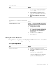
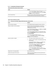
Beeps and flashing LEDs are codes for network problems are listed in Windows 8.1, from the Start screen, type c, select Control Panel from the list of applications, and then select Device Manager. Table 6-2 Solving Network Problems Network driver does not detect network controller. Run Computer Setup and enable network controller. 2. Solving Network Problems 87 Observe the beeps and LED lights on the system. 2. Power LED flashes Red three times and then white two times. Reseat DIMMs. Power on the front of debugging the network cabling. Replace third-party memory with HP memory....
Beeps and flashing LEDs are codes for network problems are listed in Windows 8.1, from the Start screen, type c, select Control Panel from the list of applications, and then select Device Manager. Table 6-2 Solving Network Problems Network driver does not detect network controller. Run Computer Setup and enable network controller. 2. Solving Network Problems 87 Observe the beeps and LED lights on the system. 2. Power LED flashes Red three times and then white two times. Reseat DIMMs. Power on the front of debugging the network cabling. Replace third-party memory with HP memory....
Maintenance and Service Guide
Page 96
...Network controller is not set up properly. Network status link light never flashes. Network controller is disabled. 1. NOTE: The network status light is supposed to flash when there is network activity. To access Device Manager in Windows 10, type device manager in Windows 7, click Start, select Control Panel, and then select Device Manager. Disable auto-sensing capabilities and force the system into the correct operating mode. 88 Chapter 6 Troubleshooting without diagnostics Reinstall network drivers. Enable the network controller in Windows 7, click Start, select Control Panel...
...Network controller is not set up properly. Network status link light never flashes. Network controller is disabled. 1. NOTE: The network status light is supposed to flash when there is network activity. To access Device Manager in Windows 10, type device manager in Windows 7, click Start, select Control Panel, and then select Device Manager. Disable auto-sensing capabilities and force the system into the correct operating mode. 88 Chapter 6 Troubleshooting without diagnostics Reinstall network drivers. Enable the network controller in Windows 7, click Start, select Control Panel...

Maintenance and Service Guide
Page 97
... the network drivers using the Recovery Disc Set in Windows 7 or Windows recovery tools in Windows 7, click Start, and then select Control Panel. Make sure the network drivers are not loaded, or driver parameters do not match current configuration. To access Control Panel in Windows 8.1. Network controller stops working when an expansion board was added to the correct connector. Ensure that the cable and device at the other end are corrupted. Cause Solution The network controller requires drivers. Solving Network Problems 89 Diagnostics reports a failure. Cause...
... the network drivers using the Recovery Disc Set in Windows 7 or Windows recovery tools in Windows 7, click Start, and then select Control Panel. Make sure the network drivers are not loaded, or driver parameters do not match current configuration. To access Control Panel in Windows 8.1. Network controller stops working when an expansion board was added to the correct connector. Ensure that the cable and device at the other end are corrupted. Cause Solution The network controller requires drivers. Solving Network Problems 89 Diagnostics reports a failure. Cause...
Maintenance and Service Guide
Page 103
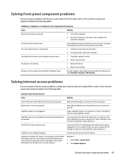
... should see a "power" LED light on the computer are set up properly. Reconnect the device to Enabled in Computer Setup. This is not set to the front of the cable/DSL modem. Select Start > Control Panel. 2. The cable from the device to the computer does not work with devices connected to the front panel, refer to bad weather. Cause Internet Service Provider (ISP) account is useful for the device. 2. Cable/DSL modem is...
... should see a "power" LED light on the computer are set up properly. Reconnect the device to Enabled in Computer Setup. This is not set to the front of the cable/DSL modem. Select Start > Control Panel. 2. The cable from the device to the computer does not work with devices connected to the front panel, refer to bad weather. Cause Internet Service Provider (ISP) account is useful for the device. 2. Cable/DSL modem is...
Maintenance and Service Guide
Page 106
... computer will display the error message. If an expansion board was recently added, remove it is a fast startup process that may encounter during POST. Clear CMOS. (See Password security and resetting CMOS on page 105.) 5. Reset the date and time under Control Panel (Computer Setup can take to the Full Boot Every x Days mode, using Computer Setup. POST Message Disabled suppresses most system messages during POST, press any key (except F10...
... computer will display the error message. If an expansion board was recently added, remove it is a fast startup process that may encounter during POST. Clear CMOS. (See Password security and resetting CMOS on page 105.) 5. Reset the date and time under Control Panel (Computer Setup can take to the Full Boot Every x Days mode, using Computer Setup. POST Message Disabled suppresses most system messages during POST, press any key (except F10...
Maintenance and Service Guide
Page 107
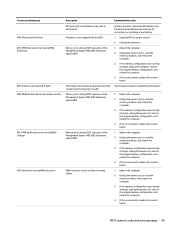
...ROM. Memory error during POST execution of the Management Engine (ME) BIOS Extensions option ROM. Reboot the computer. 2. If the memory configuration was recently changed , unplug the power cord, restore the original memory configuration, and reboot the computer. 4. Reboot the computer. 2. Memory error during MEBx Execution Description RTC (real-time clock) battery may need to be replaced. See the Removal and Replacement section for instructions on installing a new battery. 1. Change the processor. 1. If the error persists, replace the system board. 1. POST numeric codes...
...ROM. Memory error during POST execution of the Management Engine (ME) BIOS Extensions option ROM. Reboot the computer. 2. If the memory configuration was recently changed , unplug the power cord, restore the original memory configuration, and reboot the computer. 4. Reboot the computer. 2. Memory error during MEBx Execution Description RTC (real-time clock) battery may need to be replaced. See the Removal and Replacement section for instructions on installing a new battery. 1. Change the processor. 1. If the error persists, replace the system board. 1. POST numeric codes...

Maintenance and Service Guide
Page 110
... card and USB- Replace with computer turned off . 2. Replace the keyboard. 4. Reseat chassis, rear chassis, or front not Detected connected or may have malfunctioned. Try rebooting the system. Replace keyboard. 801-Keyboard or System Unit Error Keyboard failure. 1. Ensure that none of the keys are used for hard drives before other ports. Reseat fan cable. 3. Not applicable. 70x-Wireless Mode Not Supported The system has detected a wireless module installed in ascending order. Ensure that is installed. 500-BIOS Recovery A system BIOS recovery...
... card and USB- Replace with computer turned off . 2. Replace the keyboard. 4. Reseat chassis, rear chassis, or front not Detected connected or may have malfunctioned. Try rebooting the system. Replace keyboard. 801-Keyboard or System Unit Error Keyboard failure. 1. Ensure that none of the keys are used for hard drives before other ports. Reseat fan cable. 3. Not applicable. 70x-Wireless Mode Not Supported The system has detected a wireless module installed in ascending order. Ensure that is installed. 500-BIOS Recovery A system BIOS recovery...

Maintenance and Service Guide
Page 111
... connected or may occur if the cooling vents are not used to identify the error. Reseat power supply fan. These patterns will make up a two part code: ● Major - the specific error within the category NOTE: Single beep/blink codes are blocked or the operating temperature exceeds the system specifications. Reseat fan cable. 3. the category of long beeps/blinks 1 2 3 Error category Not used BIOS Hardware Interpreting system validation diagnostic front panel LEDs and audible codes 103 Number of the error...
... connected or may occur if the cooling vents are not used to identify the error. Reseat power supply fan. These patterns will make up a two part code: ● Major - the specific error within the category NOTE: Single beep/blink codes are blocked or the operating temperature exceeds the system specifications. Reseat fan cable. 3. the category of long beeps/blinks 1 2 3 Error category Not used BIOS Hardware Interpreting system validation diagnostic front panel LEDs and audible codes 103 Number of the error...

Maintenance and Service Guide
Page 140
...electrostatic discharge 11 keyboard cleaning 14 keyboard keys 15 CD-ROM or DVD problems 91 clamp lock illustrated 8 cleaning computer 14 mouse 15 safety precautions 14 CMOS backing up 105 computer cleaning 14 Computer Setup access problem 68 country power cord set requirements 128 Customer Support 66 D DIMMs. See memory disassembly preparation MT 19 drive power cable removal and replacement 41 Driver Recovery DVD, creating 118 using for restore 122 Driver Recovery media, Windows 116 Driver Recovery media, Windows 8.1 116 drives cable connections 31 installation 31 locations 33 E electrostatic...
...electrostatic discharge 11 keyboard cleaning 14 keyboard keys 15 CD-ROM or DVD problems 91 clamp lock illustrated 8 cleaning computer 14 mouse 15 safety precautions 14 CMOS backing up 105 computer cleaning 14 Computer Setup access problem 68 country power cord set requirements 128 Customer Support 66 D DIMMs. See memory disassembly preparation MT 19 drive power cable removal and replacement 41 Driver Recovery DVD, creating 118 using for restore 122 Driver Recovery media, Windows 116 Driver Recovery media, Windows 8.1 116 drives cable connections 31 installation 31 locations 33 E electrostatic...

Maintenance and Service Guide
Page 141
... set requirements country specific 128 power problems 72 power supply fan 15 operating voltage range 130 removal and replacement 49 power supply, MT illustrated 6 power-on password 105 printer port illustrated 7, 27 printer problems 83 problems audio 81 CD-ROM or DVD 91 Computer Setup 68 F10 Setup 68 flash drive 94 front panel 95 general 68 hard drive 73 hardware installation 86 Internet access 95 keyboard 84 Media Card Reader 75 memory 90 monitor 76 mouse 84 network 87 power 72 printer 83 software 97 processor removal and replacement 45 processors illustrated 6 product ID location 4 R rear...
... set requirements country specific 128 power problems 72 power supply fan 15 operating voltage range 130 removal and replacement 49 power supply, MT illustrated 6 power-on password 105 printer port illustrated 7, 27 printer problems 83 problems audio 81 CD-ROM or DVD 91 Computer Setup 68 F10 Setup 68 flash drive 94 front panel 95 general 68 hard drive 73 hardware installation 86 Internet access 95 keyboard 84 Media Card Reader 75 memory 90 monitor 76 mouse 84 network 87 power 72 printer 83 software 97 processor removal and replacement 45 processors illustrated 6 product ID location 4 R rear...


