
Hardware Reference Guide
Page 1
Hardware Reference Guide HP Compaq Pro 6305 Microtower Business PC HP Compaq Pro 6305 Small Form Factor Business PC
Hardware Reference Guide HP Compaq Pro 6305 Microtower Business PC HP Compaq Pro 6305 Small Form Factor Business PC
Hardware Reference Guide
Page 2
... reproduced, or translated to change without the prior written consent of Hewlett-Packard Company. Hardware Reference Guide HP Compaq Pro 6305 Microtower Business PC HP Compaq Pro 6305 Small Form Factor Business PC First Edition (August 2012) Document part number: 700967-001 No part of Microsoft Corporation in... another language without notice. The only warranties for technical or editorial errors or omissions contained herein. HP shall not be liable for HP products and services are either trademarks or registered trademarks of this document may be construed as constituting an...
... reproduced, or translated to change without the prior written consent of Hewlett-Packard Company. Hardware Reference Guide HP Compaq Pro 6305 Microtower Business PC HP Compaq Pro 6305 Small Form Factor Business PC First Edition (August 2012) Document part number: 700967-001 No part of Microsoft Corporation in... another language without notice. The only warranties for technical or editorial errors or omissions contained herein. HP shall not be liable for HP products and services are either trademarks or registered trademarks of this document may be construed as constituting an...
Hardware Reference Guide
Page 5
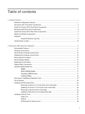
Table of contents 1 Product Features ...1 Standard Configuration Features ...1 Microtower (MT) Front Panel Components 2 Small Form Factor (SFF) Front Panel Components 3 Microtower (MT) Rear Panel Components 4 Small Form Factor (SFF) Rear Panel Components 5 Media Card Reader Components ...5 Keyboard ...7 Using the Windows Logo Key 8 Serial Number Location ...10 2 Microtower (MT) Hardware Upgrades ...11 ...Hard Drive from a Drive Bay 32 Installing a Hard Drive into an Internal Drive Bay 33 Installing a Security Lock ...37 Cable Lock ...37 Padlock ...37 HP Business PC Security Lock 38 v
Table of contents 1 Product Features ...1 Standard Configuration Features ...1 Microtower (MT) Front Panel Components 2 Small Form Factor (SFF) Front Panel Components 3 Microtower (MT) Rear Panel Components 4 Small Form Factor (SFF) Rear Panel Components 5 Media Card Reader Components ...5 Keyboard ...7 Using the Windows Logo Key 8 Serial Number Location ...10 2 Microtower (MT) Hardware Upgrades ...11 ...Hard Drive from a Drive Bay 32 Installing a Hard Drive into an Internal Drive Bay 33 Installing a Security Lock ...37 Cable Lock ...37 Padlock ...37 HP Business PC Security Lock 38 v
Hardware Reference Guide
Page 6
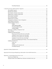
Front Bezel Security ...42 3 Small Form Factor (SFF) Hardware Upgrades 44 Serviceability Features ...44 Warnings and Cautions ...44 Removing the Computer Access Panel 45 Replacing the Computer Access Panel 46 Removing the ... a 3.5-inch Drive into a Drive Bay 69 Removing and Replacing the Primary 3.5-inch Internal Hard Drive 71 Installing a Security Lock ...75 Cable Lock ...75 Padlock ...75 HP Business PC Security Lock 76 Front Bezel Security ...80 Appendix A Battery Replacement ...82 Appendix B Removing and Replacing a Removable 3.5-inch SATA Hard Drive 85 Appendix C Unlocking...
Front Bezel Security ...42 3 Small Form Factor (SFF) Hardware Upgrades 44 Serviceability Features ...44 Warnings and Cautions ...44 Removing the Computer Access Panel 45 Replacing the Computer Access Panel 46 Removing the ... a 3.5-inch Drive into a Drive Bay 69 Removing and Replacing the Primary 3.5-inch Internal Hard Drive 71 Installing a Security Lock ...75 Cable Lock ...75 Padlock ...75 HP Business PC Security Lock 76 Front Bezel Security ...80 Appendix A Battery Replacement ...82 Appendix B Removing and Replacing a Removable 3.5-inch SATA Hard Drive 85 Appendix C Unlocking...
Hardware Reference Guide
Page 9
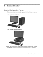
Figure 1-1 Microtower Configuration Figure 1-2 Small Form Factor Configuration NOTE: The Small Form Factor computer can also be used in this guide. For more information, see Changing from Desktop to Tower Configuration on some computer models only). Standard Configuration Features 1 For a complete listing of the hardware and software installed in the computer, run the diagnostic utility (included on page 49 in a tower orientation. 1 Product Features Standard Configuration Features Features may vary depending on the model.
Figure 1-1 Microtower Configuration Figure 1-2 Small Form Factor Configuration NOTE: The Small Form Factor computer can also be used in this guide. For more information, see Changing from Desktop to Tower Configuration on some computer models only). Standard Configuration Features 1 For a complete listing of the hardware and software installed in the computer, run the diagnostic utility (included on page 49 in a tower orientation. 1 Product Features Standard Configuration Features Features may vary depending on the model.
Hardware Reference Guide
Page 11
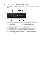
... asking if you want to interpret the code. If it is flashing red, there is a problem with the computer and it is displaying a diagnostic code. Small Form Factor (SFF) Front Panel Components 3 You can reconfigure the connector at any time in the Realtek HD Audio Manager. Some models have a bezel blank covering one... or more drive bays. Refer to the Maintenance and Service Guide to use the connector for a microphone Line-In device or a headphone. Small Form Factor (SFF) Front Panel Components Drive configuration may vary by model.
... asking if you want to interpret the code. If it is flashing red, there is a problem with the computer and it is displaying a diagnostic code. Small Form Factor (SFF) Front Panel Components 3 You can reconfigure the connector at any time in the Realtek HD Audio Manager. Some models have a bezel blank covering one... or more drive bays. Refer to the Maintenance and Service Guide to use the connector for a microphone Line-In device or a headphone. Small Form Factor (SFF) Front Panel Components Drive configuration may vary by model.
Hardware Reference Guide
Page 13
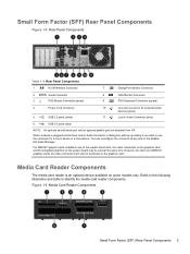
... board slots, the video connectors on the graphics card and the integrated graphics on some models only. Figure 1-6 Media Card Reader Components Small Form Factor (SFF) Rear Panel Components 5 Refer to the following illustration and table to use the connector for powered audio devices (green) 11...an optional parallel port are available from HP. Media Card Reader Components The media card reader is plugged into the blue Line-In Audio Connector, a dialog box will only be used at any time in the Realtek HD Audio Manager. Small Form Factor (SFF) Rear Panel Components Figure ...
... board slots, the video connectors on the graphics card and the integrated graphics on some models only. Figure 1-6 Media Card Reader Components Small Form Factor (SFF) Rear Panel Components 5 Refer to the following illustration and table to use the connector for powered audio devices (green) 11...an optional parallel port are available from HP. Media Card Reader Components The media card reader is plugged into the blue Line-In Audio Connector, a dialog box will only be used at any time in the Realtek HD Audio Manager. Small Form Factor (SFF) Rear Panel Components Figure ...
Hardware Reference Guide
Page 18
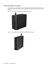
Figure 1-8 Microtower Serial Number and Product ID Location Figure 1-9 Small Form Factor Serial Number and Product ID Location 10 Chapter 1 Product Features Keep these numbers available for use when contacting customer service for assistance. Serial Number Location Each computer has a unique serial number and a product ID number that are located on the top cover of the computer.
Figure 1-8 Microtower Serial Number and Product ID Location Figure 1-9 Small Form Factor Serial Number and Product ID Location 10 Chapter 1 Product Features Keep these numbers available for use when contacting customer service for assistance. Serial Number Location Each computer has a unique serial number and a product ID number that are located on the top cover of the computer.
Hardware Reference Guide
Page 52
... reduce the risk of the applicable instructions, cautions, and warnings in this chapter. Disconnect power to internal components. 44 Chapter 3 Small Form Factor (SFF) Hardware Upgrades No tools are discharged of the computer or optional equipment. It describes proper workstation, setup, posture, and health... and work habits for more information. This guide is easily accessible at http://www.hp.com/ergo. Replace and secure the enclosure before removing the enclosure. The grounding plug is always applied to upgrade and service....
... reduce the risk of the applicable instructions, cautions, and warnings in this chapter. Disconnect power to internal components. 44 Chapter 3 Small Form Factor (SFF) Hardware Upgrades No tools are discharged of the computer or optional equipment. It describes proper workstation, setup, posture, and health... and work habits for more information. This guide is easily accessible at http://www.hp.com/ergo. Replace and secure the enclosure before removing the enclosure. The grounding plug is always applied to upgrade and service....
Hardware Reference Guide
Page 54
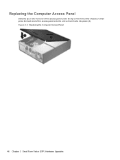
Figure 3-2 Replacing the Computer Access Panel 46 Chapter 3 Small Form Factor (SFF) Hardware Upgrades Replacing the Computer Access Panel Slide the lip on the front end of the access panel under the lip on the front of the chassis (1) then press the back end of the access panel onto the unit so that it locks into place (2).
Figure 3-2 Replacing the Computer Access Panel 46 Chapter 3 Small Form Factor (SFF) Hardware Upgrades Replacing the Computer Access Panel Slide the lip on the front end of the access panel under the lip on the front of the chassis (1) then press the back end of the access panel onto the unit so that it locks into place (2).
Hardware Reference Guide
Page 56
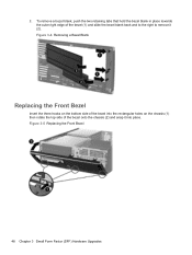
2. Figure 3-5 Replacing the Front Bezel 48 Chapter 3 Small Form Factor (SFF) Hardware Upgrades To remove a bezel blank, push the two retaining tabs that hold the bezel blank in place towards the outer right edge of the bezel onto the chassis (2) and snap it (2). Figure 3-4 Removing a Bezel Blank Replacing the Front Bezel Insert the three hooks on the bottom side of the bezel into the rectangular holes on the chassis (1) then rotate the top side of the bezel (1) and slide the bezel blank back and to the right to remove it into place.
2. Figure 3-5 Replacing the Front Bezel 48 Chapter 3 Small Form Factor (SFF) Hardware Upgrades To remove a bezel blank, push the two retaining tabs that hold the bezel blank in place towards the outer right edge of the bezel onto the chassis (2) and snap it (2). Figure 3-4 Removing a Bezel Blank Replacing the Front Bezel Insert the three hooks on the bottom side of the bezel into the rectangular holes on the chassis (1) then rotate the top side of the bezel (1) and slide the bezel blank back and to the right to remove it into place.
Hardware Reference Guide
Page 57
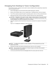
...: To stabilize the computer in a tower orientation, HP recommends the use of the power-on state, voltage is facing down and place the computer in the optional stand. Figure 3-6 Changing from Desktop to Tower Configuration 49 Changing from Desktop to Tower Configuration The Small Form Factor computer can be used in a tower orientation with...
...: To stabilize the computer in a tower orientation, HP recommends the use of the power-on state, voltage is facing down and place the computer in the optional stand. Figure 3-6 Changing from Desktop to Tower Configuration 49 Changing from Desktop to Tower Configuration The Small Form Factor computer can be used in a tower orientation with...
Hardware Reference Guide
Page 58
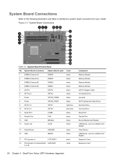
... Media Card Reader USB Device, such as a Media Card Reader Hood Sensor USB Device, such as a Media Card Reader Expansion Card Expansion Card 50 Chapter 3 Small Form Factor (SFF) Hardware Upgrades Figure 3-7 System Board Connections Table 3-1 System Board Connections No.
... Media Card Reader USB Device, such as a Media Card Reader Hood Sensor USB Device, such as a Media Card Reader Expansion Card Expansion Card 50 Chapter 3 Small Form Factor (SFF) Hardware Upgrades Figure 3-7 System Board Connections Table 3-1 System Board Connections No.
Hardware Reference Guide
Page 60
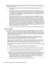
... before adding or removing memory modules. When upgrading the memory, it is assigned to single channel. Disconnect the power cord from the stand. 52 Chapter 3 Small Form Factor (SFF) Hardware Upgrades Regardless of the power-on state, voltage is determined by briefly touching a grounded metal object. Adding or removing memory modules while voltage...
... before adding or removing memory modules. When upgrading the memory, it is assigned to single channel. Disconnect the power cord from the stand. 52 Chapter 3 Small Form Factor (SFF) Hardware Upgrades Regardless of the power-on state, voltage is determined by briefly touching a grounded metal object. Adding or removing memory modules while voltage...
Hardware Reference Guide
Page 62
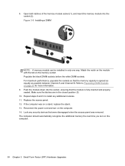
... additional memory the next time you turn on the computer. 14. Match the notch on the module with the tab on the computer. 54 Chapter 3 Small Form Factor (SFF) Hardware Upgrades Populate the black DIMM sockets before the white DIMM sockets. If the computer was removed. Repeat steps 8 and 9 to Populating DIMM Sockets...
... additional memory the next time you turn on the computer. 14. Match the notch on the module with the tab on the computer. 54 Chapter 3 Small Form Factor (SFF) Hardware Upgrades Populate the black DIMM sockets before the white DIMM sockets. If the computer was removed. Repeat steps 8 and 9 to Populating DIMM Sockets...
Hardware Reference Guide
Page 64
... the expansion slot cover or the existing expansion card. Figure 3-11 Removing an Expansion Slot Cover b. Figure 3-12 Removing a Standard PCI Expansion Card 56 Chapter 3 Small Form Factor (SFF) Hardware Upgrades NOTE: Before removing an installed expansion card, disconnect any cables that may be attached to scrape the card against the other components...
... the expansion slot cover or the existing expansion card. Figure 3-11 Removing an Expansion Slot Cover b. Figure 3-12 Removing a Standard PCI Expansion Card 56 Chapter 3 Small Form Factor (SFF) Hardware Upgrades NOTE: Before removing an installed expansion card, disconnect any cables that may be attached to scrape the card against the other components...
Hardware Reference Guide
Page 66
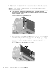
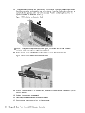
... secure the expansion card. Reconnect the power cord and turn on a stand, replace the stand. 17. If the computer was on the computer. 58 Chapter 3 Small Form Factor (SFF) Hardware Upgrades Figure 3-14 Installing an Expansion Card NOTE: When installing an expansion card, press firmly on the card so that the bracket on...
... secure the expansion card. Reconnect the power cord and turn on a stand, replace the stand. 17. If the computer was on the computer. 58 Chapter 3 Small Form Factor (SFF) Hardware Upgrades Figure 3-14 Installing an Expansion Card NOTE: When installing an expansion card, press firmly on the card so that the bracket on...
Hardware Reference Guide
Page 68
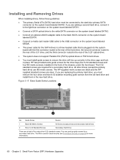
...80 for a secondary hard drive. If you are silver. Four are required for more information). 60 Chapter 3 Small Form Factor (SFF) Hardware Upgrades Figure 3-17 Extra Guide Screw Locations No. HP has provided extra guide screws for a secondary hard drive. If you must be connected to the USB connector on... at total of five extra silver 6-32 standard screws. All other drives (except the primary hard drive) use M3 metric screws. The HP-supplied metric screws are black and the HPsupplied standard screws are adding a second hard drive, connect it to the light blue connector on ...
...80 for a secondary hard drive. If you are silver. Four are required for more information). 60 Chapter 3 Small Form Factor (SFF) Hardware Upgrades Figure 3-17 Extra Guide Screw Locations No. HP has provided extra guide screws for a secondary hard drive. If you must be connected to the USB connector on... at total of five extra silver 6-32 standard screws. All other drives (except the primary hard drive) use M3 metric screws. The HP-supplied metric screws are black and the HPsupplied standard screws are adding a second hard drive, connect it to the light blue connector on ...
Hardware Reference Guide
Page 70
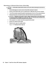
...: All removable media should be taken out of a drive before removing the drive from the computer. 3. Figure 3-18 Rotating the Drive Cage Up 62 Chapter 3 Small Form Factor (SFF) Hardware Upgrades CAUTION: Regardless of the computer. 5. Remove all removable media, such as the system is on the system board as long as compact...
...: All removable media should be taken out of a drive before removing the drive from the computer. 3. Figure 3-18 Rotating the Drive Cage Up 62 Chapter 3 Small Form Factor (SFF) Hardware Upgrades CAUTION: Regardless of the computer. 5. Remove all removable media, such as the system is on the system board as long as compact...
Hardware Reference Guide
Page 72
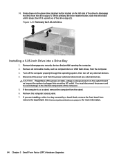
... the bezel blank. Remove the computer access panel. 7. Remove all removable media, such as the system is on page 47 for more information. 64 Chapter 3 Small Form Factor (SFF) Hardware Upgrades
... the bezel blank. Remove the computer access panel. 7. Remove all removable media, such as the system is on page 47 for more information. 64 Chapter 3 Small Form Factor (SFF) Hardware Upgrades


