Hardware Reference Guide
Page 5
Table of contents 1 Product Features ...1 Standard Configuration Features ...1 Microtower (MT) Front Panel Components 2 Small Form Factor (SFF) Front Panel Components 3 Microtower (MT) Rear Panel Components 4 Small Form Factor (SFF) Rear Panel Components 5 Media Card Reader Components ...5 Keyboard ...7 Using the Windows Logo Key 8 Serial Number Location ...10 2 Microtower (MT) Hardware Upgrades ...11 ...a Hard Drive from a Drive Bay 32 Installing a Hard Drive into an Internal Drive Bay 33 Installing a Security Lock ...37 Cable Lock ...37 Padlock ...37 HP Business PC Security Lock 38 v
Table of contents 1 Product Features ...1 Standard Configuration Features ...1 Microtower (MT) Front Panel Components 2 Small Form Factor (SFF) Front Panel Components 3 Microtower (MT) Rear Panel Components 4 Small Form Factor (SFF) Rear Panel Components 5 Media Card Reader Components ...5 Keyboard ...7 Using the Windows Logo Key 8 Serial Number Location ...10 2 Microtower (MT) Hardware Upgrades ...11 ...a Hard Drive from a Drive Bay 32 Installing a Hard Drive into an Internal Drive Bay 33 Installing a Security Lock ...37 Cable Lock ...37 Padlock ...37 HP Business PC Security Lock 38 v
Hardware Reference Guide
Page 6
Front Bezel Security ...42 3 Small Form Factor (SFF) Hardware Upgrades 44 Serviceability Features ...44 Warnings and Cautions ...44 Removing the Computer Access Panel 45 Replacing the Computer Access Panel 46 Removing the Front ... a 3.5-inch Drive into a Drive Bay 69 Removing and Replacing the Primary 3.5-inch Internal Hard Drive 71 Installing a Security Lock ...75 Cable Lock ...75 Padlock ...75 HP Business PC Security Lock 76 Front Bezel Security ...80 Appendix A Battery Replacement ...82 Appendix B Removing and Replacing a Removable 3.5-inch SATA Hard Drive 85 Appendix C Unlocking...
Front Bezel Security ...42 3 Small Form Factor (SFF) Hardware Upgrades 44 Serviceability Features ...44 Warnings and Cautions ...44 Removing the Computer Access Panel 45 Replacing the Computer Access Panel 46 Removing the Front ... a 3.5-inch Drive into a Drive Bay 69 Removing and Replacing the Primary 3.5-inch Internal Hard Drive 71 Installing a Security Lock ...75 Cable Lock ...75 Padlock ...75 HP Business PC Security Lock 76 Front Bezel Security ...80 Appendix A Battery Replacement ...82 Appendix B Removing and Replacing a Removable 3.5-inch SATA Hard Drive 85 Appendix C Unlocking...
Hardware Reference Guide
Page 11
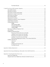
... is displaying a diagnostic code. Refer to the Maintenance and Service Guide to use the connector for a microphone Line-In device or a headphone. Small Form Factor (SFF) Front Panel Components 3 If it is flashing red, there is a problem with the computer and it is on. Small Form Factor...
... is displaying a diagnostic code. Refer to the Maintenance and Service Guide to use the connector for a microphone Line-In device or a headphone. Small Form Factor (SFF) Front Panel Components 3 If it is flashing red, there is a problem with the computer and it is on. Small Form Factor...
Hardware Reference Guide
Page 13
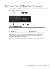
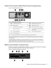
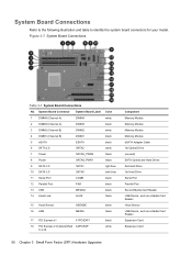
Small Form Factor (SFF) Rear Panel Components Figure 1-5 Rear Panel Components Table 1-4 Rear Panel Components 1 RJ-45 Network Connector 7 DisplayPort Monitor Connector 2 Serial Connector 3 PS/2 Mouse Connector (green) 8 VGA ...-In Audio Connector (blue) 6 USB 3.0 ports (blue) NOTE: An optional second serial port and an optional parallel port are available from HP. Figure 1-6 Media Card Reader Components Small Form Factor (SFF) Rear Panel Components 5 For AMD/ATI graphic cards installed in the Realtek HD Audio Manager. However, for other non-AMD/ATI...
Small Form Factor (SFF) Rear Panel Components Figure 1-5 Rear Panel Components Table 1-4 Rear Panel Components 1 RJ-45 Network Connector 7 DisplayPort Monitor Connector 2 Serial Connector 3 PS/2 Mouse Connector (green) 8 VGA ...-In Audio Connector (blue) 6 USB 3.0 ports (blue) NOTE: An optional second serial port and an optional parallel port are available from HP. Figure 1-6 Media Card Reader Components Small Form Factor (SFF) Rear Panel Components 5 For AMD/ATI graphic cards installed in the Realtek HD Audio Manager. However, for other non-AMD/ATI...
Hardware Reference Guide
Page 52
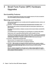
3 Small Form Factor (SFF) Hardware Upgrades Serviceability Features The computer includes features that make it easy to the equipment before removing ... or telephone connectors into an AC power source, voltage is always applied to internal components. 44 Chapter 3 Small Form Factor (SFF) Hardware Upgrades WARNING! To reduce the risk of the installation procedures described in this guide. Replace and secure the enclosure before opening...is plugged into the network interface controller (NIC) receptacles. When the computer is easily accessible at http://www.hp.com/ergo.
3 Small Form Factor (SFF) Hardware Upgrades Serviceability Features The computer includes features that make it easy to the equipment before removing ... or telephone connectors into an AC power source, voltage is always applied to internal components. 44 Chapter 3 Small Form Factor (SFF) Hardware Upgrades WARNING! To reduce the risk of the installation procedures described in this guide. Replace and secure the enclosure before opening...is plugged into the network interface controller (NIC) receptacles. When the computer is easily accessible at http://www.hp.com/ergo.
Hardware Reference Guide
Page 54
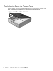
Figure 3-2 Replacing the Computer Access Panel 46 Chapter 3 Small Form Factor (SFF) Hardware Upgrades Replacing the Computer Access Panel Slide the lip on the front end of the access panel under the lip on the front of the chassis (1) then press the back end of the access panel onto the unit so that it locks into place (2).
Figure 3-2 Replacing the Computer Access Panel 46 Chapter 3 Small Form Factor (SFF) Hardware Upgrades Replacing the Computer Access Panel Slide the lip on the front end of the access panel under the lip on the front of the chassis (1) then press the back end of the access panel onto the unit so that it locks into place (2).
Hardware Reference Guide
Page 56
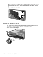
2. Figure 3-5 Replacing the Front Bezel 48 Chapter 3 Small Form Factor (SFF) Hardware Upgrades Figure 3-4 Removing a Bezel Blank Replacing the Front Bezel Insert the three hooks on the bottom side of the bezel into the rectangular holes on the chassis (1) then rotate the top side of the bezel (1) and slide the bezel blank back and to the right to remove it into place. To remove a bezel blank, push the two retaining tabs that hold the bezel blank in place towards the outer right edge of the bezel onto the chassis (2) and snap it (2).
2. Figure 3-5 Replacing the Front Bezel 48 Chapter 3 Small Form Factor (SFF) Hardware Upgrades Figure 3-4 Removing a Bezel Blank Replacing the Front Bezel Insert the three hooks on the bottom side of the bezel into the rectangular holes on the chassis (1) then rotate the top side of the bezel (1) and slide the bezel blank back and to the right to remove it into place. To remove a bezel blank, push the two retaining tabs that hold the bezel blank in place towards the outer right edge of the bezel onto the chassis (2) and snap it (2).
Hardware Reference Guide
Page 58
... USB Device, such as a Media Card Reader Hood Sensor USB Device, such as a Media Card Reader Expansion Card Expansion Card 50 Chapter 3 Small Form Factor (SFF) Hardware Upgrades
... USB Device, such as a Media Card Reader Hood Sensor USB Device, such as a Media Card Reader Expansion Card Expansion Card 50 Chapter 3 Small Form Factor (SFF) Hardware Upgrades
Hardware Reference Guide
Page 60
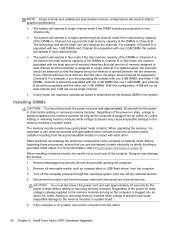
... important to use memory modules with gold-plated metal contacts to prevent corrosion and/or oxidation resulting from the stand. 52 Chapter 3 Small Form Factor (SFF) Hardware Upgrades Static electricity can vary between the two channels. Remove/disengage any external devices. 4. NOTE: Single channel and unbalanced dual channel memory configurations will...
... important to use memory modules with gold-plated metal contacts to prevent corrosion and/or oxidation resulting from the stand. 52 Chapter 3 Small Form Factor (SFF) Hardware Upgrades Static electricity can vary between the two channels. Remove/disengage any external devices. 4. NOTE: Single channel and unbalanced dual channel memory configurations will...
Hardware Reference Guide
Page 62
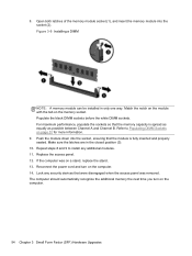
If the computer was removed. Match the notch on the module with the tab on the computer. 54 Chapter 3 Small Form Factor (SFF) Hardware Upgrades For maximum performance, populate the sockets so that the memory capacity is fully inserted and properly seated. Refer to install any security devices ...
If the computer was removed. Match the notch on the module with the tab on the computer. 54 Chapter 3 Small Form Factor (SFF) Hardware Upgrades For maximum performance, populate the sockets so that the memory capacity is fully inserted and properly seated. Refer to install any security devices ...
Hardware Reference Guide
Page 64
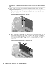
... cables that may be attached to scrape the card against the other components. Figure 3-12 Removing a Standard PCI Expansion Card 56 Chapter 3 Small Form Factor (SFF) Hardware Upgrades a. Figure 3-11 Removing an Expansion Slot Cover b.
... cables that may be attached to scrape the card against the other components. Figure 3-12 Removing a Standard PCI Expansion Card 56 Chapter 3 Small Form Factor (SFF) Hardware Upgrades a. Figure 3-11 Removing an Expansion Slot Cover b.
Hardware Reference Guide
Page 66
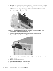
Connect external cables to the installed card, if needed . 15. If the computer was on the computer. 58 Chapter 3 Small Form Factor (SFF) Hardware Upgrades Figure 3-15 Closing the Expansion Slot Retainer 14. Replace the computer access panel. 16. To install a new expansion card, hold the card just ...
Connect external cables to the installed card, if needed . 15. If the computer was on the computer. 58 Chapter 3 Small Form Factor (SFF) Hardware Upgrades Figure 3-15 Closing the Expansion Slot Retainer 14. Replace the computer access panel. 16. To install a new expansion card, hold the card just ...
Hardware Reference Guide
Page 68
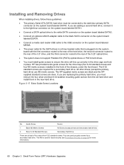
... second connector routed to the rear of the 3.5" drive, and the third connector routed to the rear of the chassis, under the front bezel. The HP-supplied metric screws are black and the HPsupplied standard screws are required for the drive bays (five 6-32 standard screws and four M3 metric screws.... ● Connect a media card reader USB cable to the dark blue primary SATA connector on page 80 for more information). 60 Chapter 3 Small Form Factor (SFF) Hardware Upgrades If you must install guide screws to ensure the drive will line up correctly in the drive cage and lock in the new...
... second connector routed to the rear of the 3.5" drive, and the third connector routed to the rear of the chassis, under the front bezel. The HP-supplied metric screws are black and the HPsupplied standard screws are required for the drive bays (five 6-32 standard screws and four M3 metric screws.... ● Connect a media card reader USB cable to the dark blue primary SATA connector on page 80 for more information). 60 Chapter 3 Small Form Factor (SFF) Hardware Upgrades If you must install guide screws to ensure the drive will line up correctly in the drive cage and lock in the new...
Hardware Reference Guide
Page 70
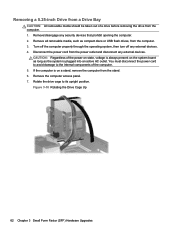
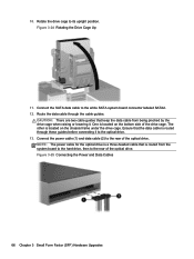
... the computer is always present on a stand, remove the computer from the computer. 1. Figure 3-18 Rotating the Drive Cage Up 62 Chapter 3 Small Form Factor (SFF) Hardware Upgrades Removing a 5.25-inch Drive from a Drive Bay CAUTION: All removable media should be taken out of a drive before removing the drive from the...
... the computer is always present on a stand, remove the computer from the computer. 1. Figure 3-18 Rotating the Drive Cage Up 62 Chapter 3 Small Form Factor (SFF) Hardware Upgrades Removing a 5.25-inch Drive from a Drive Bay CAUTION: All removable media should be taken out of a drive before removing the drive from the...
Hardware Reference Guide
Page 72
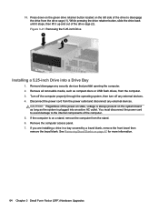
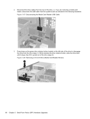
... active AC outlet. Disconnect the power cord from the computer. 3. If the computer is on page 47 for more information. 64 Chapter 3 Small Form Factor (SFF) Hardware Upgrades Press down on the green drive retainer button located on the system board as long as compact discs or USB flash drives, from...
... active AC outlet. Disconnect the power cord from the computer. 3. If the computer is on page 47 for more information. 64 Chapter 3 Small Form Factor (SFF) Hardware Upgrades Press down on the green drive retainer button located on the system board as long as compact discs or USB flash drives, from...
Hardware Reference Guide
Page 74
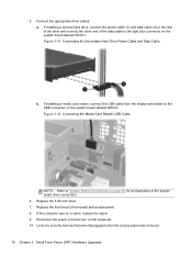
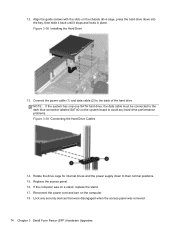
... guides that is located on the chassis frame under the drive cage. Figure 3-25 Connecting the Power and Data Cables 66 Chapter 3 Small Form Factor (SFF) Hardware Upgrades NOTE: The power cable for the optical drive is a three-headed cable that keep the data cable from the system board to the...
... guides that is located on the chassis frame under the drive cage. Figure 3-25 Connecting the Power and Data Cables 66 Chapter 3 Small Form Factor (SFF) Hardware Upgrades NOTE: The power cable for the optical drive is a three-headed cable that keep the data cable from the system board to the...
Hardware Reference Guide
Page 76
.... Disconnect the drive cables from the rear of the drive cage (2). 2. Figure 3-28 Removing a 3.5-inch Drive (Media Card Reader Shown) 68 Chapter 3 Small Form Factor (SFF) Hardware Upgrades
.... Disconnect the drive cables from the rear of the drive cage (2). 2. Figure 3-28 Removing a 3.5-inch Drive (Media Card Reader Shown) 68 Chapter 3 Small Form Factor (SFF) Hardware Upgrades
Hardware Reference Guide
Page 78
... Reader USB Cable NOTE: Refer to the light blue connector on a stand, replace the stand. 9. If the computer was removed. 70 Chapter 3 Small Form Factor (SFF) Hardware Upgrades Lock any security devices that were disengaged when the access panel was on the system board labeled SATA1. 5. Figure 3-31 Connecting the Secondary...
... Reader USB Cable NOTE: Refer to the light blue connector on a stand, replace the stand. 9. If the computer was removed. 70 Chapter 3 Small Form Factor (SFF) Hardware Upgrades Lock any security devices that were disengaged when the access panel was on the system board labeled SATA1. 5. Figure 3-31 Connecting the Secondary...
Hardware Reference Guide
Page 80
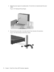
The hard drive is located beneath the power supply. Figure 3-35 Disconnecting the Hard Drive Cables 72 Chapter 3 Small Form Factor (SFF) Hardware Upgrades Rotate the power supply to its upright position. Figure 3-34 Raising the Power Supply 9. Disconnect the power cable (1) and data cable (2) from the back of the hard drive. 8.
The hard drive is located beneath the power supply. Figure 3-35 Disconnecting the Hard Drive Cables 72 Chapter 3 Small Form Factor (SFF) Hardware Upgrades Rotate the power supply to its upright position. Figure 3-34 Raising the Power Supply 9. Disconnect the power cable (1) and data cable (2) from the back of the hard drive. 8.
Hardware Reference Guide
Page 82
... cable must be connected to the dark blue connector labeled SATA0 on the computer. 18. If the computer was removed. 74 Chapter 3 Small Form Factor (SFF) Hardware Upgrades 12. Figure 3-38 Installing the Hard Drive 13. Rotate the drive cage for internal drives and the power supply down into the bay...
... cable must be connected to the dark blue connector labeled SATA0 on the computer. 18. If the computer was removed. 74 Chapter 3 Small Form Factor (SFF) Hardware Upgrades 12. Figure 3-38 Installing the Hard Drive 13. Rotate the drive cage for internal drives and the power supply down into the bay...


