Hardware Reference Guide
Page 5
... Panel Components 4 Small Form Factor (SFF) Rear Panel Components 5 Media Card Reader Components ...5 Keyboard ...7 Using the Windows Logo Key 8 Serial Number Location ...10 2 Microtower (MT) Hardware Upgrades ...11 Serviceability Features ...11 Warnings and Cautions ...11 Removing the Computer Access Panel 12 Replacing the Computer Access Panel 13 Removing the Front ... Removing a Hard Drive from a Drive Bay 32 Installing a Hard Drive into an Internal Drive Bay 33 Installing a Security Lock ...37 Cable Lock ...37 Padlock ...37 HP Business PC Security Lock 38 v
... Panel Components 4 Small Form Factor (SFF) Rear Panel Components 5 Media Card Reader Components ...5 Keyboard ...7 Using the Windows Logo Key 8 Serial Number Location ...10 2 Microtower (MT) Hardware Upgrades ...11 Serviceability Features ...11 Warnings and Cautions ...11 Removing the Computer Access Panel 12 Replacing the Computer Access Panel 13 Removing the Front ... Removing a Hard Drive from a Drive Bay 32 Installing a Hard Drive into an Internal Drive Bay 33 Installing a Security Lock ...37 Cable Lock ...37 Padlock ...37 HP Business PC Security Lock 38 v
Hardware Reference Guide
Page 10
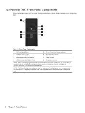
... to interpret the code. 2 Chapter 1 Product Features If it is flashing red, there is a problem with the computer and it is displaying a diagnostic code. Microtower (MT) Front Panel Components Drive configuration may vary by model.
... to interpret the code. 2 Chapter 1 Product Features If it is flashing red, there is a problem with the computer and it is displaying a diagnostic code. Microtower (MT) Front Panel Components Drive configuration may vary by model.

Hardware Reference Guide
Page 12
... 10 USB 3.0 ports (blue) 11 USB 2.0 ports (black) NOTE: An optional second serial port and an optional parallel port are available from HP. When a device is plugged into the blue Line-In Audio Connector, a dialog box will only be functional on the system board may be used... at any time in device or a microphone. Microtower (MT) Rear Panel Components Figure 1-4 Rear Panel Components Table 1-3 Rear Panel Components 1 Power Cord Connector 2 Line-In Audio Connector (blue) 6 Line-Out ...
... 10 USB 3.0 ports (blue) 11 USB 2.0 ports (black) NOTE: An optional second serial port and an optional parallel port are available from HP. When a device is plugged into the blue Line-In Audio Connector, a dialog box will only be functional on the system board may be used... at any time in device or a microphone. Microtower (MT) Rear Panel Components Figure 1-4 Rear Panel Components Table 1-3 Rear Panel Components 1 Power Cord Connector 2 Line-In Audio Connector (blue) 6 Line-Out ...
Hardware Reference Guide
Page 19
... that make it easy to the system board. The grounding plug is easily accessible at http://www.hp.com/ergo. When the computer is plugged into the network interface controller (NIC) receptacles. 2 Microtower (MT) Hardware Upgrades Serviceability Features The computer includes features that you are needed for most of the installation procedures...
... that make it easy to the system board. The grounding plug is easily accessible at http://www.hp.com/ergo. When the computer is plugged into the network interface controller (NIC) receptacles. 2 Microtower (MT) Hardware Upgrades Serviceability Features The computer includes features that you are needed for most of the installation procedures...
Hardware Reference Guide
Page 20
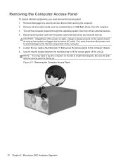
... external devices. Turn off the computer properly through the operating system, then turn off the unit (2). Figure 2-1 Removing the Computer Access Panel 12 Chapter 2 Microtower (MT) Hardware Upgrades Use the handle located between the thumbscrews to lift the access panel off any security devices that secure the access panel to the...
... external devices. Turn off the computer properly through the operating system, then turn off the unit (2). Figure 2-1 Removing the Computer Access Panel 12 Chapter 2 Microtower (MT) Hardware Upgrades Use the handle located between the thumbscrews to lift the access panel off any security devices that secure the access panel to the...
Hardware Reference Guide
Page 22
... drives, from the power outlet and disconnect any external devices. 4. Remove the computer access panel. 6. Remove the access panel and front bezel. 14 Chapter 2 Microtower (MT) Hardware Upgrades Remove all removable media, such as the system is always present on state, voltage is plugged into an active AC outlet. Remove/disengage...
... drives, from the power outlet and disconnect any external devices. 4. Remove the computer access panel. 6. Remove the access panel and front bezel. 14 Chapter 2 Microtower (MT) Hardware Upgrades Remove all removable media, such as the system is always present on state, voltage is plugged into an active AC outlet. Remove/disengage...
Hardware Reference Guide
Page 24
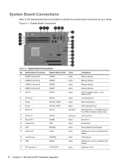
... Second Media Card Reader USB Device, such as a Media Card Reader Hood Sensor USB Device, such as a Media Card Reader Expansion Card 16 Chapter 2 Microtower (MT) Hardware Upgrades System Board Connections Refer to the following illustrations and tables to identify the system board connectors for your model.
... Second Media Card Reader USB Device, such as a Media Card Reader Hood Sensor USB Device, such as a Media Card Reader Expansion Card 16 Chapter 2 Microtower (MT) Hardware Upgrades System Board Connections Refer to the following illustrations and tables to identify the system board connectors for your model.

Hardware Reference Guide
Page 26
... of memory is spread between the channels. The memory module sockets have more information, refer to the memory modules or system board. 18 Chapter 2 Microtower (MT) Hardware Upgrades The technology and device width can damage the electronic components of the power-on state, voltage is always supplied to the memory modules...
... of memory is spread between the channels. The memory module sockets have more information, refer to the memory modules or system board. 18 Chapter 2 Microtower (MT) Hardware Upgrades The technology and device width can damage the electronic components of the power-on state, voltage is always supplied to the memory modules...
Hardware Reference Guide
Page 28
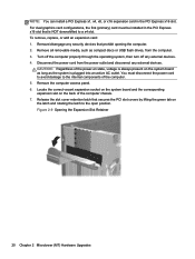
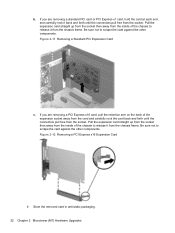
... devices. 4. Remove all removable media, such as the system is plugged into an active AC outlet. Figure 2-9 Opening the Expansion Slot Retainer 20 Chapter 2 Microtower (MT) Hardware Upgrades You must be installed in the PCI Express x16 slot. Disconnect the power cord from the computer. 3. NOTE: You can install a PCI Express...
... devices. 4. Remove all removable media, such as the system is plugged into an active AC outlet. Figure 2-9 Opening the Expansion Slot Retainer 20 Chapter 2 Microtower (MT) Hardware Upgrades You must be installed in the PCI Express x16 slot. Disconnect the power cord from the computer. 3. NOTE: You can install a PCI Express...
Hardware Reference Guide
Page 30
... c. Pull the expansion card straight up from the socket then away from the socket. Store the removed card in anti-static packaging. 22 Chapter 2 Microtower (MT) Hardware Upgrades Be sure not to release it from the inside of the chassis to scrape the card against the other components. Figure 2-12 Removing...
... c. Pull the expansion card straight up from the socket then away from the socket. Store the removed card in anti-static packaging. 22 Chapter 2 Microtower (MT) Hardware Upgrades Be sure not to release it from the inside of the chassis to scrape the card against the other components. Figure 2-12 Removing...

Hardware Reference Guide
Page 32
Reconfigure the computer, if necessary. To verify the type and size of the storage devices installed in the computer, run Computer Setup. 24 Chapter 2 Microtower (MT) Hardware Upgrades Reconnect the power cord and turn on your computer may be different than the drive configuration shown above. Lock any security devices that ...
Reconfigure the computer, if necessary. To verify the type and size of the storage devices installed in the computer, run Computer Setup. 24 Chapter 2 Microtower (MT) Hardware Upgrades Reconnect the power cord and turn on your computer may be different than the drive configuration shown above. Lock any security devices that ...

Hardware Reference Guide
Page 34
... damage to Electrostatic Discharge on or in a bubble-pack mailer or other protective packaging and label the package "Fragile: Handle With Care." 26 Chapter 2 Microtower (MT) Hardware Upgrades Do not use excessive force when inserting a drive. Guide Screw 1 Black M3 Metric Screws 2 Silver and Blue 6-32 Isolation Mounting Screws Device All...
... damage to Electrostatic Discharge on or in a bubble-pack mailer or other protective packaging and label the package "Fragile: Handle With Care." 26 Chapter 2 Microtower (MT) Hardware Upgrades Do not use excessive force when inserting a drive. Guide Screw 1 Black M3 Metric Screws 2 Silver and Blue 6-32 Isolation Mounting Screws Device All...

Hardware Reference Guide
Page 36
A latch drive bracket with release tabs secures the drives in the drive bay. Figure 2-18 Disconnecting the Media Card Reader USB Cable 7. Figure 2-19 Removing the Drives 28 Chapter 2 Microtower (MT) Hardware Upgrades b. If you want to remove, then slide the drive from the system board. Lift the release tab on the latch drive bracket (1) for the drive you are removing a media card reader, disconnect the USB cable from its drive bay (2).
A latch drive bracket with release tabs secures the drives in the drive bay. Figure 2-18 Disconnecting the Media Card Reader USB Cable 7. Figure 2-19 Removing the Drives 28 Chapter 2 Microtower (MT) Hardware Upgrades b. If you want to remove, then slide the drive from the system board. Lift the release tab on the latch drive bracket (1) for the drive you are removing a media card reader, disconnect the USB cable from its drive bay (2).
Hardware Reference Guide
Page 38
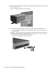
... optical drive, connect the power cable (1) and data cable (2) to the rear of the drive. Figure 2-22 Connecting the Optical Drive Cables 30 Chapter 2 Microtower (MT) Hardware Upgrades Figure 2-21 Sliding the Drives into place. Slide the drive into the drive bay, making sure to the drive as indicated in the...
... optical drive, connect the power cable (1) and data cable (2) to the rear of the drive. Figure 2-22 Connecting the Optical Drive Cables 30 Chapter 2 Microtower (MT) Hardware Upgrades Figure 2-21 Sliding the Drives into place. Slide the drive into the drive bay, making sure to the drive as indicated in the...
Hardware Reference Guide
Page 40
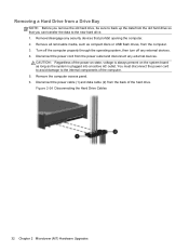
... cord from the power outlet and disconnect any external devices. 4. Remove the computer access panel. 6. Figure 2-24 Disconnecting the Hard Drive Cables 32 Chapter 2 Microtower (MT) Hardware Upgrades Removing a Hard Drive from a Drive Bay NOTE: Before you can transfer the data to the new hard drive. 1.
... cord from the power outlet and disconnect any external devices. 4. Remove the computer access panel. 6. Figure 2-24 Disconnecting the Hard Drive Cables 32 Chapter 2 Microtower (MT) Hardware Upgrades Removing a Hard Drive from a Drive Bay NOTE: Before you can transfer the data to the new hard drive. 1.
Hardware Reference Guide
Page 42
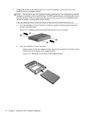
...; If you are replacing a drive, transfer the guides screws from the old drive to Installing and Removing Drives on the adapter bracket. The HP-supplied isolation mounting guide screws are installing a 2.5-inch hard drive: ◦ Slide the drive into the bay adapter bracket, ensuring the connector on...illustration of the drive). Refer to the new one. ● If you must install the drive in the Adapter Bracket 34 Chapter 2 Microtower (MT) Hardware Upgrades Figure 2-27 Sliding the 2.5-inch Drive in an adapter bracket. If you are installing a 2.5-inch drive, you are installed on ...
...; If you are replacing a drive, transfer the guides screws from the old drive to Installing and Removing Drives on the adapter bracket. The HP-supplied isolation mounting guide screws are installing a 2.5-inch hard drive: ◦ Slide the drive into the bay adapter bracket, ensuring the connector on...illustration of the drive). Refer to the new one. ● If you must install the drive in the Adapter Bracket 34 Chapter 2 Microtower (MT) Hardware Upgrades Figure 2-27 Sliding the 2.5-inch Drive in an adapter bracket. If you are installing a 2.5-inch drive, you are installed on ...

Hardware Reference Guide
Page 44
.... Figure 2-30 Sliding a Hard Drive into place. The upper bay is for an optional secondary hard drive. 7. Replace the computer access panel. 36 Chapter 2 Microtower (MT) Hardware Upgrades Slide the drive into the drive bay, making sure to the light blue connector labeled SATA1. 10. Route the power and data cables...
.... Figure 2-30 Sliding a Hard Drive into place. The upper bay is for an optional secondary hard drive. 7. Replace the computer access panel. 36 Chapter 2 Microtower (MT) Hardware Upgrades Slide the drive into the drive bay, making sure to the light blue connector labeled SATA1. 10. Route the power and data cables...
Hardware Reference Guide
Page 46
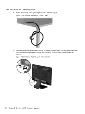
Figure 2-34 Securing the Cable to the monitor by looping it around a stationary object. Insert the cable lock into the key hole on the rear of the monitor and secure the lock to a Fixed Object 2. Figure 2-35 Installing the Cable Lock on the back of the lock and rotating the key 90 degrees. HP Business PC Security Lock 1. Fasten the security cable by inserting the key into the cable lock slot on the Monitor 38 Chapter 2 Microtower (MT) Hardware Upgrades
Figure 2-34 Securing the Cable to the monitor by looping it around a stationary object. Insert the cable lock into the key hole on the rear of the monitor and secure the lock to a Fixed Object 2. Figure 2-35 Installing the Cable Lock on the back of the lock and rotating the key 90 degrees. HP Business PC Security Lock 1. Fasten the security cable by inserting the key into the cable lock slot on the Monitor 38 Chapter 2 Microtower (MT) Hardware Upgrades
Hardware Reference Guide
Page 48
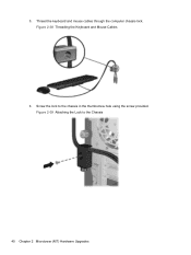
Thread the keyboard and mouse cables through the computer chassis lock. Figure 2-39 Attaching the Lock to the chassis in the thumbscrew hole using the screw provided. Figure 2-38 Threading the Keyboard and Mouse Cables 6. 5. Screw the lock to the Chassis 40 Chapter 2 Microtower (MT) Hardware Upgrades
Thread the keyboard and mouse cables through the computer chassis lock. Figure 2-39 Attaching the Lock to the chassis in the thumbscrew hole using the screw provided. Figure 2-38 Threading the Keyboard and Mouse Cables 6. 5. Screw the lock to the Chassis 40 Chapter 2 Microtower (MT) Hardware Upgrades
Hardware Reference Guide
Page 50
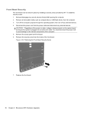
Front Bezel Security The front bezel can be locked in place by installing a security screw provided by HP. Remove all removable media, such as the system is plugged into an active AC outlet. Turn off the computer properly through the operating system, then... computer. 2. Disconnect the power cord from the computer. 3. Remove the security screw from the inside of the computer. 5. Replace the front bezel. 42 Chapter 2 Microtower (MT) Hardware Upgrades You must disconnect the power cord to avoid damage to the internal components of the front bezel. Figure 2-42 Retrieving the Front Bezel...
Front Bezel Security The front bezel can be locked in place by installing a security screw provided by HP. Remove all removable media, such as the system is plugged into an active AC outlet. Turn off the computer properly through the operating system, then... computer. 2. Disconnect the power cord from the computer. 3. Remove the security screw from the inside of the computer. 5. Replace the front bezel. 42 Chapter 2 Microtower (MT) Hardware Upgrades You must disconnect the power cord to avoid damage to the internal components of the front bezel. Figure 2-42 Retrieving the Front Bezel...


