
Hardware Reference Guide
Page 1
Hardware Reference Guide HP Compaq Pro 6305 Microtower Business PC HP Compaq Pro 6305 Small Form Factor Business PC
Hardware Reference Guide HP Compaq Pro 6305 Microtower Business PC HP Compaq Pro 6305 Small Form Factor Business PC
Hardware Reference Guide
Page 2
.... Microsoft and Windows are set forth in the United States and/or other countries. No part of Hewlett-Packard Company. Hardware Reference Guide HP Compaq Pro 6305 Microtower Business PC HP Compaq Pro 6305 Small Form Factor Business PC First Edition (August 2012) Document part number: 700967-001 The only warranties for technical or editorial errors or...
.... Microsoft and Windows are set forth in the United States and/or other countries. No part of Hewlett-Packard Company. Hardware Reference Guide HP Compaq Pro 6305 Microtower Business PC HP Compaq Pro 6305 Small Form Factor Business PC First Edition (August 2012) Document part number: 700967-001 The only warranties for technical or editorial errors or...
Hardware Reference Guide
Page 5
...) Rear Panel Components 4 Small Form Factor (SFF) Rear Panel Components 5 Media Card Reader Components ...5 Keyboard ...7 Using the Windows Logo Key 8 Serial Number Location ...10 2 Microtower (MT) Hardware Upgrades ...11 Serviceability Features ...11 Warnings and Cautions ...11 Removing the Computer Access Panel 12 Replacing the Computer Access Panel 13 Removing the ... Removing a Hard Drive from a Drive Bay 32 Installing a Hard Drive into an Internal Drive Bay 33 Installing a Security Lock ...37 Cable Lock ...37 Padlock ...37 HP Business PC Security Lock 38 v
...) Rear Panel Components 4 Small Form Factor (SFF) Rear Panel Components 5 Media Card Reader Components ...5 Keyboard ...7 Using the Windows Logo Key 8 Serial Number Location ...10 2 Microtower (MT) Hardware Upgrades ...11 Serviceability Features ...11 Warnings and Cautions ...11 Removing the Computer Access Panel 12 Replacing the Computer Access Panel 13 Removing the ... Removing a Hard Drive from a Drive Bay 32 Installing a Hard Drive into an Internal Drive Bay 33 Installing a Security Lock ...37 Cable Lock ...37 Padlock ...37 HP Business PC Security Lock 38 v
Hardware Reference Guide
Page 9
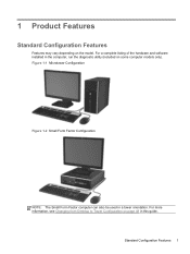
Standard Configuration Features 1 For a complete listing of the hardware and software installed in a tower orientation. 1 Product Features Standard Configuration Features Features may vary depending on page 49 in this guide. Figure 1-1 Microtower Configuration Figure 1-2 Small Form Factor Configuration NOTE: The Small Form Factor computer can also be used in the computer, run the diagnostic utility (included on some computer models only). For more information, see Changing from Desktop to Tower Configuration on the model.
Standard Configuration Features 1 For a complete listing of the hardware and software installed in a tower orientation. 1 Product Features Standard Configuration Features Features may vary depending on page 49 in this guide. Figure 1-1 Microtower Configuration Figure 1-2 Small Form Factor Configuration NOTE: The Small Form Factor computer can also be used in the computer, run the diagnostic utility (included on some computer models only). For more information, see Changing from Desktop to Tower Configuration on the model.
Hardware Reference Guide
Page 10
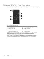
... want to interpret the code. 2 Chapter 1 Product Features If it is flashing red, there is a problem with the computer and it is displaying a diagnostic code. Microtower (MT) Front Panel Components Drive configuration may vary by model. You can reconfigure the connector at any time in the Realtek HD Audio Manager.
... want to interpret the code. 2 Chapter 1 Product Features If it is flashing red, there is a problem with the computer and it is displaying a diagnostic code. Microtower (MT) Front Panel Components Drive configuration may vary by model. You can reconfigure the connector at any time in the Realtek HD Audio Manager.

Hardware Reference Guide
Page 12
...Connector 10 USB 3.0 ports (blue) 11 USB 2.0 ports (black) NOTE: An optional second serial port and an optional parallel port are available from HP. When a device is plugged into the blue Line-In Audio Connector, a dialog box will only be used at any time in the Realtek HD... Audio Manager. You can reconfigure the connector at the same time. Microtower (MT) Rear Panel Components Figure 1-4 Rear Panel Components Table 1-3 Rear Panel Components 1 Power Cord Connector 2 Line-In Audio Connector (blue) 6 Line-...
...Connector 10 USB 3.0 ports (blue) 11 USB 2.0 ports (black) NOTE: An optional second serial port and an optional parallel port are available from HP. When a device is plugged into the blue Line-In Audio Connector, a dialog box will only be used at any time in the Realtek HD... Audio Manager. You can reconfigure the connector at the same time. Microtower (MT) Rear Panel Components Figure 1-4 Rear Panel Components Table 1-3 Rear Panel Components 1 Power Cord Connector 2 Line-In Audio Connector (blue) 6 Line-...
Hardware Reference Guide
Page 18
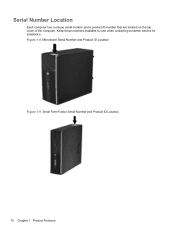
Keep these numbers available for use when contacting customer service for assistance. Serial Number Location Each computer has a unique serial number and a product ID number that are located on the top cover of the computer. Figure 1-8 Microtower Serial Number and Product ID Location Figure 1-9 Small Form Factor Serial Number and Product ID Location 10 Chapter 1 Product Features
Keep these numbers available for use when contacting customer service for assistance. Serial Number Location Each computer has a unique serial number and a product ID number that are located on the top cover of the computer. Figure 1-8 Microtower Serial Number and Product ID Location Figure 1-9 Small Form Factor Serial Number and Product ID Location 10 Chapter 1 Product Features
Hardware Reference Guide
Page 19
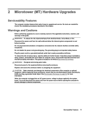
... described in this guide. When the computer is plugged into the network interface controller (NIC) receptacles. This guide is easily accessible at http://www.hp.com/ergo. 2 Microtower (MT) Hardware Upgrades Serviceability Features The computer includes features that you are needed for most of the computer or optional equipment. Do not plug...
... described in this guide. When the computer is plugged into the network interface controller (NIC) receptacles. This guide is easily accessible at http://www.hp.com/ergo. 2 Microtower (MT) Hardware Upgrades Serviceability Features The computer includes features that you are needed for most of the computer or optional equipment. Do not plug...
Hardware Reference Guide
Page 20
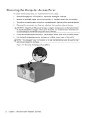
... long as compact discs or USB flash drives, from the power outlet and disconnect any external devices. Figure 2-1 Removing the Computer Access Panel 12 Chapter 2 Microtower (MT) Hardware Upgrades You must remove the access panel: 1. Remove/disengage any external devices. 4. Turn off the computer properly through the operating system, then turn...
... long as compact discs or USB flash drives, from the power outlet and disconnect any external devices. Figure 2-1 Removing the Computer Access Panel 12 Chapter 2 Microtower (MT) Hardware Upgrades You must remove the access panel: 1. Remove/disengage any external devices. 4. Turn off the computer properly through the operating system, then turn...
Hardware Reference Guide
Page 22
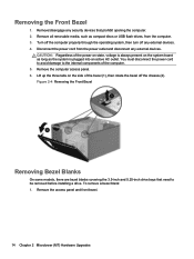
... prohibit opening the computer. 2. Disconnect the power cord from the computer. 3. Remove the computer access panel. 6. Remove the access panel and front bezel. 14 Chapter 2 Microtower (MT) Hardware Upgrades Lift up the three tabs on the system board as long as compact discs or USB flash drives, from the power outlet...
... prohibit opening the computer. 2. Disconnect the power cord from the computer. 3. Remove the computer access panel. 6. Remove the access panel and front bezel. 14 Chapter 2 Microtower (MT) Hardware Upgrades Lift up the three tabs on the system board as long as compact discs or USB flash drives, from the power outlet...
Hardware Reference Guide
Page 24
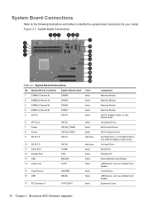
... Port Second Media Card Reader USB Device, such as a Media Card Reader Hood Sensor USB Device, such as a Media Card Reader Expansion Card 16 Chapter 2 Microtower (MT) Hardware Upgrades Figure 2-7 System Board Connections Table 2-1 System Board Connections No.
... Port Second Media Card Reader USB Device, such as a Media Card Reader Hood Sensor USB Device, such as a Media Card Reader Expansion Card 16 Chapter 2 Microtower (MT) Hardware Upgrades Figure 2-7 System Board Connections Table 2-1 System Board Connections No.

Hardware Reference Guide
Page 26
... the least amount of memory describes the total amount of the DIMMs in Channel A is assigned to the memory modules or system board. 18 Chapter 2 Microtower (MT) Hardware Upgrades For more memory than the other, the larger amount should be careful not to Electrostatic Discharge on state, voltage is determined by...
... the least amount of memory describes the total amount of the DIMMs in Channel A is assigned to the memory modules or system board. 18 Chapter 2 Microtower (MT) Hardware Upgrades For more memory than the other, the larger amount should be careful not to Electrostatic Discharge on state, voltage is determined by...
Hardware Reference Guide
Page 28
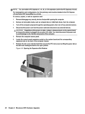
Figure 2-9 Opening the Expansion Slot Retainer 20 Chapter 2 Microtower (MT) Hardware Upgrades Remove/disengage any external devices. 4. CAUTION: Regardless of the computer chassis. 7. Locate the correct vacant expansion socket on the system board and ...
Figure 2-9 Opening the Expansion Slot Retainer 20 Chapter 2 Microtower (MT) Hardware Upgrades Remove/disengage any external devices. 4. CAUTION: Regardless of the computer chassis. 7. Locate the correct vacant expansion socket on the system board and ...
Hardware Reference Guide
Page 30
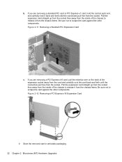
... to release it from the chassis frame. Figure 2-12 Removing a PCI Express x16 Expansion Card 9. b. Store the removed card in anti-static packaging. 22 Chapter 2 Microtower (MT) Hardware Upgrades Pull the expansion card straight up from the socket then away from the inside of the expansion socket away from the card...
... to release it from the chassis frame. Figure 2-12 Removing a PCI Express x16 Expansion Card 9. b. Store the removed card in anti-static packaging. 22 Chapter 2 Microtower (MT) Hardware Upgrades Pull the expansion card straight up from the socket then away from the inside of the expansion socket away from the card...

Hardware Reference Guide
Page 32
... than the drive configuration shown above. To verify the type and size of the storage devices installed in the computer, run Computer Setup. 24 Chapter 2 Microtower (MT) Hardware Upgrades Replace the computer access panel. 15. Drive Positions Figure 2-15 Drive Positions Table 2-2 Drive Positions 1 Two 5.25-inch drive bays for optional...
... than the drive configuration shown above. To verify the type and size of the storage devices installed in the computer, run Computer Setup. 24 Chapter 2 Microtower (MT) Hardware Upgrades Replace the computer access panel. 15. Drive Positions Figure 2-15 Drive Positions Table 2-2 Drive Positions 1 Two 5.25-inch drive bays for optional...

Hardware Reference Guide
Page 34
... a hard drive to Electrostatic Discharge on or in a bubble-pack mailer or other protective packaging and label the package "Fragile: Handle With Care." 26 Chapter 2 Microtower (MT) Hardware Upgrades Do not remove a drive while the computer is on page 92. Guide Screw 1 Black M3 Metric Screws 2 Silver and Blue 6-32 Isolation...
... a hard drive to Electrostatic Discharge on or in a bubble-pack mailer or other protective packaging and label the package "Fragile: Handle With Care." 26 Chapter 2 Microtower (MT) Hardware Upgrades Do not remove a drive while the computer is on page 92. Guide Screw 1 Black M3 Metric Screws 2 Silver and Blue 6-32 Isolation...

Hardware Reference Guide
Page 36
Lift the release tab on the latch drive bracket (1) for the drive you are removing a media card reader, disconnect the USB cable from its drive bay (2). A latch drive bracket with release tabs secures the drives in the drive bay. Figure 2-19 Removing the Drives 28 Chapter 2 Microtower (MT) Hardware Upgrades Figure 2-18 Disconnecting the Media Card Reader USB Cable 7. b. If you want to remove, then slide the drive from the system board.
Lift the release tab on the latch drive bracket (1) for the drive you are removing a media card reader, disconnect the USB cable from its drive bay (2). A latch drive bracket with release tabs secures the drives in the drive bay. Figure 2-19 Removing the Drives 28 Chapter 2 Microtower (MT) Hardware Upgrades Figure 2-18 Disconnecting the Media Card Reader USB Cable 7. b. If you want to remove, then slide the drive from the system board.
Hardware Reference Guide
Page 38
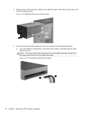
Figure 2-21 Sliding the Drives into place. Figure 2-22 Connecting the Optical Drive Cables 30 Chapter 2 Microtower (MT) Hardware Upgrades 8. Slide the drive into the drive bay, making sure to the rear of the drive. a. NOTE: The power cable for the optical ...
Figure 2-21 Sliding the Drives into place. Figure 2-22 Connecting the Optical Drive Cables 30 Chapter 2 Microtower (MT) Hardware Upgrades 8. Slide the drive into the drive bay, making sure to the rear of the drive. a. NOTE: The power cable for the optical ...
Hardware Reference Guide
Page 40
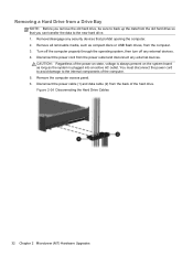
... can transfer the data to the internal components of the computer. 5. Remove the computer access panel. 6. Figure 2-24 Disconnecting the Hard Drive Cables 32 Chapter 2 Microtower (MT) Hardware Upgrades You must disconnect the power cord to avoid damage to the new hard drive. 1. Disconnect the power cord from the back of...
... can transfer the data to the internal components of the computer. 5. Remove the computer access panel. 6. Figure 2-24 Disconnecting the Hard Drive Cables 32 Chapter 2 Microtower (MT) Hardware Upgrades You must disconnect the power cord to avoid damage to the new hard drive. 1. Disconnect the power cord from the back of...
Hardware Reference Guide
Page 42
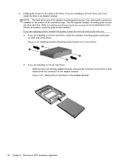
The HP-supplied isolation mounting guide screws are installed on the exterior of the drive). Figure 2-27 Sliding the 2.5-inch Drive in a 3.5-inch Drive ● If you ... adapter bracket. NOTE: The hard drive uses 6-32 isolation mounting guide screws. Figure 2-26 Installing Isolation Mounting Guide Screws in the Adapter Bracket 34 Chapter 2 Microtower (MT) Hardware Upgrades 6.
The HP-supplied isolation mounting guide screws are installed on the exterior of the drive). Figure 2-27 Sliding the 2.5-inch Drive in a 3.5-inch Drive ● If you ... adapter bracket. NOTE: The hard drive uses 6-32 isolation mounting guide screws. Figure 2-26 Installing Isolation Mounting Guide Screws in the Adapter Bracket 34 Chapter 2 Microtower (MT) Hardware Upgrades 6.


