HP Pavilion dv9500 Hard Drive Removal - Entertainment Notebook PC
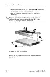
HP Pavilion dv9500 Hard Drive Removal
View Results Below
Free HP Pavilion dv9500 manuals!
Problems with HP Pavilion dv9500?
Ask a Question
Free HP Pavilion dv9500 manuals!
Problems with HP Pavilion dv9500?
Ask a Question
Related Manual Pages


Similar Questions

Changing Hard Drive
can't locate and determine how to access the hard drive to install a new drive.
can't locate and determine how to access the hard drive to install a new drive.
(Posted by larryallen1837 8 years ago)


Notebook Won't Boot, Hard Drive Tries To Spool Up To Speed But Can't.
Product is an HP Pavilion DV9500 notebook, manufactured in 2008. The battery is completely dead. I p...
Product is an HP Pavilion DV9500 notebook, manufactured in 2008. The battery is completely dead. I p...
(Posted by rsfirebaugh 12 years ago)

Remove Hard Drive
I'm replacing the keyboard in my dv7-3058dx and one of the screws for the keyboard I believe is unde...
I'm replacing the keyboard in my dv7-3058dx and one of the screws for the keyboard I believe is unde...
(Posted by twhitehouse 13 years ago)