Safety and Regulatory Information Desktops, Thin Clients, and Personal Workstations
Page 28
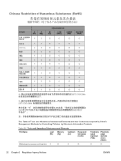
... 2-2 Toxic and Hazardous Substances and Elements Part Name Lead (Pb) Mercury (Hg) Cadmium (Cd) Hexavalent Chromium (Cr(VI)) Polybrominated biphenyls (PBB) Polybrominated diphenyl ethers (PBDE) Motherboard, processor and heat sink X O O O O O 22 Chapter 2 Regulatory Agency Notices ENWW
... 2-2 Toxic and Hazardous Substances and Elements Part Name Lead (Pb) Mercury (Hg) Cadmium (Cd) Hexavalent Chromium (Cr(VI)) Polybrominated biphenyls (PBB) Polybrominated diphenyl ethers (PBDE) Motherboard, processor and heat sink X O O O O O 22 Chapter 2 Regulatory Agency Notices ENWW
Start Here Guide
Page 10
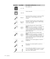
NOTE: This Audio In connector is connected to the motherboard and located on the back of the computer, to headphones. Microphone In connector (pink) to connect to the TV tuner. Composite Video 2 Secondary Composite video ... a USB connector. 4 Start Here You must use the Audio In connector, which is connected to a microphone. NOTE: This Audio In connector is connected to the motherboard and located on the back of the computer, to record audio only. (Select models only.) Headphones Out connector (green) to connect to record audio only...
NOTE: This Audio In connector is connected to the motherboard and located on the back of the computer, to headphones. Microphone In connector (pink) to connect to the TV tuner. Composite Video 2 Secondary Composite video ... a USB connector. 4 Start Here You must use the Audio In connector, which is connected to a microphone. NOTE: This Audio In connector is connected to the motherboard and located on the back of the computer, to record audio only. (Select models only.) Headphones Out connector (green) to connect to record audio only...
Start Here Guide
Page 12
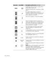
... audio configuration is activated. Center Rear Audio Line In (blue) connector to connect to connect from set -top box. Line Side (gray) connector to the motherboard. NOTE: Audio can be recorded by using this primary left audio input from a set-top box output connector. Line Rear (black) connector to connect a TV...
... audio configuration is activated. Center Rear Audio Line In (blue) connector to connect to connect from set -top box. Line Side (gray) connector to the motherboard. NOTE: Audio can be recorded by using this primary left audio input from a set-top box output connector. Line Rear (black) connector to connect a TV...

Start Here Guide
Page 13
... FM In port on the back of the computer on the front of the computer. Digital Audio Out Digital audio input (white) connects to the motherboard. Setting Up Your Computer 7 Connector Icon/label A/V In Audio 1 R TV/Cable Ant FM Ant Analog Video Description and function (continued) Primary right audio input from...
... FM In port on the back of the computer on the front of the computer. Digital Audio Out Digital audio input (white) connects to the motherboard. Setting Up Your Computer 7 Connector Icon/label A/V In Audio 1 R TV/Cable Ant FM Ant Analog Video Description and function (continued) Primary right audio input from...
Upgrading and Servicing Guide
Page 18
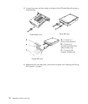
4 Connect the power and data cables to a secondary hard disk drive (select models only). B - See "Opening and Closing the Computer" on page 1. 14 Upgrading and Servicing Guide Connect to the back of the HP Pocket Media Drive bay or hard disk drive. Pocket Media Drive A B MASTER C SLAVE To CPU Parallel ATA drive Serial ATA drive A - Connect to the computer motherboard. 5 Replace the front and side panels, and close the computer. C - Connect to a primary hard disk drive.
4 Connect the power and data cables to a secondary hard disk drive (select models only). B - See "Opening and Closing the Computer" on page 1. 14 Upgrading and Servicing Guide Connect to the back of the HP Pocket Media Drive bay or hard disk drive. Pocket Media Drive A B MASTER C SLAVE To CPU Parallel ATA drive Serial ATA drive A - Connect to the computer motherboard. 5 Replace the front and side panels, and close the computer. C - Connect to a primary hard disk drive.
Upgrading and Servicing Guide
Page 24
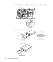
Connect to the computer motherboard. C - B - Serial ATA drive 20 Upgrading and Servicing Guide Connect to a secondary hard disk drive (select models only). 4 Align the four guides on the bottom of the hard disk drive cage with the four holes on the back of the chassis, and then slide the cage down toward the bottom of the chassis until it locks into place. 5 Attach the hard disk drive cables. A B MASTER C SLAVE To CPU Parallel ATA drive A - Connect to a primary hard disk drive.
Connect to the computer motherboard. C - B - Serial ATA drive 20 Upgrading and Servicing Guide Connect to a secondary hard disk drive (select models only). 4 Align the four guides on the bottom of the hard disk drive cage with the four holes on the back of the chassis, and then slide the cage down toward the bottom of the chassis until it locks into place. 5 Attach the hard disk drive cables. A B MASTER C SLAVE To CPU Parallel ATA drive A - Connect to a primary hard disk drive.
Upgrading and Servicing Guide
Page 26
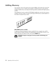
.... WARNING: Using the wrong type of computer that your computer. The computer is shipped with one or more memory modules installed, but you have. The motherboard contains sockets for specific memory module information and specifications, go to the Web site listed in -line memory modules). Adding Memory Your computer comes with...
.... WARNING: Using the wrong type of computer that your computer. The computer is shipped with one or more memory modules installed, but you have. The motherboard contains sockets for specific memory module information and specifications, go to the Web site listed in -line memory modules). Adding Memory Your computer comes with...
Upgrading and Servicing Guide
Page 28
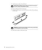
Doing so may damage the module. 6 Move any of the contacts. WARNING: Do not pull the memory module out of the memory socket. 24 Upgrading and Servicing Guide 5 Locate the memory sockets on each end of the memory socket until the module pops out of the socket. Always use the retaining clips to touch any cabling out of the way, if necessary. 7 Push down the retaining clip on the motherboard. CAUTION: When handling a memory module, be careful not to remove the module. 8 Lift the memory module out of the memory socket.
Doing so may damage the module. 6 Move any of the contacts. WARNING: Do not pull the memory module out of the memory socket. 24 Upgrading and Servicing Guide 5 Locate the memory sockets on each end of the memory socket until the module pops out of the socket. Always use the retaining clips to touch any cabling out of the way, if necessary. 7 Push down the retaining clip on the motherboard. CAUTION: When handling a memory module, be careful not to remove the module. 8 Lift the memory module out of the memory socket.

Upgrading and Servicing Guide
Page 32
... panels. See "Opening and Closing the Computer" on page 1. 2 Gently lay the computer on its side. 3 On the back of the sharp edges on the motherboard.
... panels. See "Opening and Closing the Computer" on page 1. 2 Gently lay the computer on its side. 3 On the back of the sharp edges on the motherboard.

Upgrading and Servicing Guide
Page 35
... equivalent battery. The battery has an estimated life expectancy of explosion if the battery is incorrectly replaced. See "Opening and Closing the Computer" on the motherboard provides backup power for the computer timekeeping capability. Discard used batteries according to the manufacturer's instructions. 1 Prepare the computer to weaken, the date and time...
... equivalent battery. The battery has an estimated life expectancy of explosion if the battery is incorrectly replaced. See "Opening and Closing the Computer" on the motherboard provides backup power for the computer timekeeping capability. Discard used batteries according to the manufacturer's instructions. 1 Prepare the computer to weaken, the date and time...

