Memory Modules
Page 5
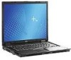
Lift the memory module compartment cover 2 away from the computer. Memory Modules 1-3 Loosen the memory module compartment cover screw 1. 8. Adding or replacing memory modules 7.
Lift the memory module compartment cover 2 away from the computer. Memory Modules 1-3 Loosen the memory module compartment cover screw 1. 8. Adding or replacing memory modules 7.
Memory Modules
Page 8
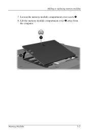
Tighten the memory module compartment cover screw 3. 14. Reconnect external power and external devices. 16. Turn on the computer. 12. Close the cover 2. 13. Replace the battery pack. 15. Adding or replacing memory modules 11. Align the tabs 1 on the memory module compartment cover with the notches on the computer. 1-6 Memory Modules
Tighten the memory module compartment cover screw 3. 14. Reconnect external power and external devices. 16. Turn on the computer. 12. Close the cover 2. 13. Replace the battery pack. 15. Adding or replacing memory modules 11. Align the tabs 1 on the memory module compartment cover with the notches on the computer. 1-6 Memory Modules
Memory Modules
Page 10
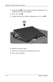
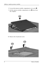
Loosen the memory module compartment cover screw 1. 8. Remove the 2 keyboard screws. 1-8 Memory Modules Adding or replacing memory modules 7. Lift the memory module compartment cover 2 away from the computer. 9.
Loosen the memory module compartment cover screw 1. 8. Remove the 2 keyboard screws. 1-8 Memory Modules Adding or replacing memory modules 7. Lift the memory module compartment cover 2 away from the computer. 9.
Memory Modules
Page 16
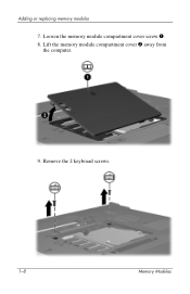
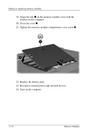
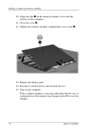
Close the cover 2. 21. Replace the battery pack. 23. Reconnect external power and external devices. 24. Tighten the memory module compartment cover screw 3. 22. Turn on the computer. 20. Align the tabs 1 on the memory module cover with the notches on the computer. 1-14 Memory Modules Adding or replacing memory modules 19.
Close the cover 2. 21. Replace the battery pack. 23. Reconnect external power and external devices. 24. Tighten the memory module compartment cover screw 3. 22. Turn on the computer. 20. Align the tabs 1 on the memory module cover with the notches on the computer. 1-14 Memory Modules Adding or replacing memory modules 19.

Memory Modules - Windows Vista
Page 5
Loosen the memory module compartment cover screw 1. 9. Lift the memory module compartment cover 2 away from the computer. Memory Modules 3 Adding or replacing memory modules 8.
Loosen the memory module compartment cover screw 1. 9. Lift the memory module compartment cover 2 away from the computer. Memory Modules 3 Adding or replacing memory modules 8.
Memory Modules - Windows Vista
Page 8
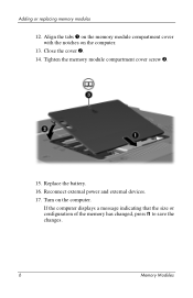
Reconnect external power and external devices. 17. Tighten the memory module compartment cover screw 3. 15. Replace the battery. 16. If the computer displays a message indicating that the size or configuration of the memory has changed, press f1 to save the changes. 6 Memory Modules Turn on the computer. 13. Close the cover 2. 14. Adding or replacing memory modules 12. Align the tabs 1 on the memory module compartment cover with the notches on the computer.
Reconnect external power and external devices. 17. Tighten the memory module compartment cover screw 3. 15. Replace the battery. 16. If the computer displays a message indicating that the size or configuration of the memory has changed, press f1 to save the changes. 6 Memory Modules Turn on the computer. 13. Close the cover 2. 14. Adding or replacing memory modules 12. Align the tabs 1 on the memory module compartment cover with the notches on the computer.
Memory Modules - Windows Vista
Page 10
Remove the 2 keyboard screws. 8 Memory Modules Loosen the memory module compartment cover screw 1. 9. Adding or replacing memory modules 8. Lift the memory module compartment cover 2 away from the computer. 10.
Remove the 2 keyboard screws. 8 Memory Modules Loosen the memory module compartment cover screw 1. 9. Adding or replacing memory modules 8. Lift the memory module compartment cover 2 away from the computer. 10.
Memory Modules - Windows Vista
Page 16
Adding or replacing memory modules 20. Align the tabs 1 on the memory module cover with the notches on the computer. If the computer displays a message indicating that the size or configuration of the memory has changed, press f1 to save the changes. 14 Memory Modules Tighten the memory module compartment cover screw 3. 23. Reconnect external power and external devices. 25. Replace the battery pack. 24. Close the cover 2. 22. Turn on the computer. 21.
Adding or replacing memory modules 20. Align the tabs 1 on the memory module cover with the notches on the computer. If the computer displays a message indicating that the size or configuration of the memory has changed, press f1 to save the changes. 14 Memory Modules Tighten the memory module compartment cover screw 3. 23. Reconnect external power and external devices. 25. Replace the battery pack. 24. Close the cover 2. 22. Turn on the computer. 21.

Maintenance and Service Guide
Page 65
... 8a 8b 8c 8d 9 10 11 12 13 14 Description Spare Part Number Plastics Kit 413704-001 Includes: RTC battery Microphone Memory/Mini Card module cover (includes 1 captive screw) Hard drive cover (includes 2 captive screws) Not illustrated: Computer feet (6) PC Card slot space savers (2) Modem module 399441-001 Mini Card WWAN module 399440...
... 8a 8b 8c 8d 9 10 11 12 13 14 Description Spare Part Number Plastics Kit 413704-001 Includes: RTC battery Microphone Memory/Mini Card module cover (includes 1 captive screw) Hard drive cover (includes 2 captive screws) Not illustrated: Computer feet (6) PC Card slot space savers (2) Modem module 399441-001 Mini Card WWAN module 399440...

Maintenance and Service Guide
Page 76
Illustrated Parts Catalog 3.3 Plastics Kit Item 1 2 3 4 5 6 7 Table 3-2 Plastics Kit Spare Part Number Information Description Spare Part Number Plastics Kit Includes: 413704-001 Memory/Mini Card module cover (includes 1 captive screw) Hard drive cover (includes 2 captive screws) RTC battery Computer feet (6) ExpressCard slot space saver PC Card slot space saver Microphone 3-22 Maintenance and Service Guide
Illustrated Parts Catalog 3.3 Plastics Kit Item 1 2 3 4 5 6 7 Table 3-2 Plastics Kit Spare Part Number Information Description Spare Part Number Plastics Kit Includes: 413704-001 Memory/Mini Card module cover (includes 1 captive screw) Hard drive cover (includes 2 captive screws) RTC battery Computer feet (6) ExpressCard slot space saver PC Card slot space saver Microphone 3-22 Maintenance and Service Guide

Maintenance and Service Guide
Page 105
...Computer for Disassembly Battery 0 Hard Drive 2 loosened to remove the hard drive cover 1 loosened to remove the hard drive 4 to remove the hard drive frame Computer Feet 0 Bluetooth Module 0 External Memory Module 1 loosened to be referenced when removing computer components. Removal and Replacement... Procedures 5.2 Disassembly Sequence Chart Use the chart below to determine the section number to remove the memory/Mini Card module cover Mini Card WLAN Module 2 Ä To prevent an unresponsive system and the display of a warning message, replace ...
...Computer for Disassembly Battery 0 Hard Drive 2 loosened to remove the hard drive cover 1 loosened to remove the hard drive 4 to remove the hard drive frame Computer Feet 0 Bluetooth Module 0 External Memory Module 1 loosened to be referenced when removing computer components. Removal and Replacement... Procedures 5.2 Disassembly Sequence Chart Use the chart below to determine the section number to remove the memory/Mini Card module cover Mini Card WLAN Module 2 Ä To prevent an unresponsive system and the display of a warning message, replace ...

Maintenance and Service Guide
Page 106
...a device and then receive a warning message, remove the device to restore computer functionality. Then contact Customer Care. Switch Cover 2 Display Assembly 6 Top Cover 15 Speaker 1 Microphone 0 Modem Module 2 USB/Audio Board 1 System Board 1 screw 4 screw locks Serial Connector ... 5.23 5.24 5.25 Description # of Screws Removed Keyboard 2 Fan 2 loosened Heat Sink 4 loosened Processor 1 loosened RTC Battery 0 Internal Memory Module 0 Mini Card WWAN Module 2 Å To prevent an unresponsive system and the display of a warning message, install only a Mini Card...
...a device and then receive a warning message, remove the device to restore computer functionality. Then contact Customer Care. Switch Cover 2 Display Assembly 6 Top Cover 15 Speaker 1 Microphone 0 Modem Module 2 USB/Audio Board 1 System Board 1 screw 4 screw locks Serial Connector ... 5.23 5.24 5.25 Description # of Screws Removed Keyboard 2 Fan 2 loosened Heat Sink 4 loosened Processor 1 loosened RTC Battery 0 Internal Memory Module 0 Mini Card WWAN Module 2 Å To prevent an unresponsive system and the display of a warning message, install only a Mini Card...

Maintenance and Service Guide
Page 116
Remove the memory/Mini Card module cover. ✎ The memory/Mini Card module cover is included in the Plastics Kit, spare part number 413704-001. Removing the Memory/Mini Card Module Cover 5-14 Maintenance and Service Guide Loosen the Phillips PM2.0×4.0 screw 1 that secures the memory/Mini Card module cover to the computer. 4. Removal and Replacement Procedures 3. Lift the rear edge of the cover 2 up and swing it toward you. 5.
Remove the memory/Mini Card module cover. ✎ The memory/Mini Card module cover is included in the Plastics Kit, spare part number 413704-001. Removing the Memory/Mini Card Module Cover 5-14 Maintenance and Service Guide Loosen the Phillips PM2.0×4.0 screw 1 that secures the memory/Mini Card module cover to the computer. 4. Removal and Replacement Procedures 3. Lift the rear edge of the cover 2 up and swing it toward you. 5.

Maintenance and Service Guide
Page 120
Remove the memory/Mini Card module cover (Section 5.7). 3. Position the computer with the front toward you. 5-18 Maintenance and Service Guide Aruba Austria Azerbaijan Bahrain Belgium Bermuda Bulgaria Cayman Islands Columbia Croatia ...
Remove the memory/Mini Card module cover (Section 5.7). 3. Position the computer with the front toward you. 5-18 Maintenance and Service Guide Aruba Austria Azerbaijan Bahrain Belgium Bermuda Bulgaria Cayman Islands Columbia Croatia ...

Maintenance and Service Guide
Page 122
Position the computer with the right side toward you. 5-20 Maintenance and Service Guide Prepare the computer for disassembly (Section 5.3). 2. Removal and Replacement Procedures 5.9 Optical Drive Optical Drive Spare Part Number Information 24X Max CD-ROM drive 8X Max DVD-ROM drive 4X Max DVD±RW and CD-RW Combo Drive 8X Max DVD±RW and CD-RW Combo Drive 24X Max DVD/CD-RW Combo Drive 413698-001 413699-001 413700-001 413702-001 413701-101 1. Remove the memory/Mini Card module cover (Section 5.7). 3.
Position the computer with the right side toward you. 5-20 Maintenance and Service Guide Prepare the computer for disassembly (Section 5.3). 2. Removal and Replacement Procedures 5.9 Optical Drive Optical Drive Spare Part Number Information 24X Max CD-ROM drive 8X Max DVD-ROM drive 4X Max DVD±RW and CD-RW Combo Drive 8X Max DVD±RW and CD-RW Combo Drive 24X Max DVD/CD-RW Combo Drive 413698-001 413699-001 413700-001 413702-001 413701-101 1. Remove the memory/Mini Card module cover (Section 5.7). 3.

Maintenance and Service Guide
Page 126
...-251 416039-171 416039-231 416039-BA1 416039-071 416039-B71 416039-111 416039-AB1 416039-281 416039-141 416039-031 416039-001 1. Remove the memory/Mini Card module cover (Section 5.7). 5-24 Maintenance and Service Guide
...-251 416039-171 416039-231 416039-BA1 416039-071 416039-B71 416039-111 416039-AB1 416039-281 416039-141 416039-031 416039-001 1. Remove the memory/Mini Card module cover (Section 5.7). 5-24 Maintenance and Service Guide

Maintenance and Service Guide
Page 145
Remove the keyboard (Section 5.10). 4. Remove the switch cover (Section 5.17) Maintenance and Service Guide 5-43 Removal and Replacement Procedures 5.18 Display Assembly Display Assembly Spare Part Number Information Display assemblies...) 15.0-inch, SXGA+WVA, TFT 15.0-inch, XGA, TFT, with BrightView 430967-001 430966-001 Display assemblies for disassembly (Section 5.3). 2. Remove the memory compartment cover (Section 5.7) and disconnect the wireless antenna cables from the Mini Card WLAN module (Section 5.8). 3. Prepare the computer for use with computer models without WWAN...
Remove the keyboard (Section 5.10). 4. Remove the switch cover (Section 5.17) Maintenance and Service Guide 5-43 Removal and Replacement Procedures 5.18 Display Assembly Display Assembly Spare Part Number Information Display assemblies...) 15.0-inch, SXGA+WVA, TFT 15.0-inch, XGA, TFT, with BrightView 430967-001 430966-001 Display assemblies for disassembly (Section 5.3). 2. Remove the memory compartment cover (Section 5.7) and disconnect the wireless antenna cables from the Mini Card WLAN module (Section 5.8). 3. Prepare the computer for use with computer models without WWAN...

Maintenance and Service Guide
Page 148
Removal and Replacement Procedures 5.19 Top Cover Top Cover Spare Part Number Information For use with full-featured computer models with pointing stick and fingerprint reader For use with full-featured computer ... upside down with defeatured computer models Fingerprint reader board (not illustrated; Prepare the computer for disassembly (Section 5.3), and then remove the following components: a. Memory/Mini Card module cover (Section 5.7) c. includes fingerprint reader board cable) 413673-001 413674-001 413675-001 413672-001 413695-001 1. Optical drive (Section 5.9) d. Switch...
Removal and Replacement Procedures 5.19 Top Cover Top Cover Spare Part Number Information For use with full-featured computer models with pointing stick and fingerprint reader For use with full-featured computer ... upside down with defeatured computer models Fingerprint reader board (not illustrated; Prepare the computer for disassembly (Section 5.3), and then remove the following components: a. Memory/Mini Card module cover (Section 5.7) c. includes fingerprint reader board cable) 413673-001 413674-001 413675-001 413672-001 413695-001 1. Optical drive (Section 5.9) d. Switch...

Maintenance and Service Guide
Page 153
Prepare the computer for disassembly (Section 5.3), and then remove the following components: a. Keyboard (Section 5.10) e. Memory/Mini Card module cover (Section 5.7) c. 5.20 Speaker Removal and Replacement Procedures Speaker Speaker Spare Part Number Information 413697-001 1. Display assembly (Section 5.18) g. Optical drive (Section 5.9) d. Top cover (Section 5.19) Maintenance and Service Guide 5-51 Switch cover (Section 5.17) f. Hard drive (Section 5.4) b.
Prepare the computer for disassembly (Section 5.3), and then remove the following components: a. Keyboard (Section 5.10) e. Memory/Mini Card module cover (Section 5.7) c. 5.20 Speaker Removal and Replacement Procedures Speaker Speaker Spare Part Number Information 413697-001 1. Display assembly (Section 5.18) g. Optical drive (Section 5.9) d. Top cover (Section 5.19) Maintenance and Service Guide 5-51 Switch cover (Section 5.17) f. Hard drive (Section 5.4) b.

Maintenance and Service Guide
Page 156
Optical drive (Section 5.9) d. Hard drive (Section 5.4) b. Memory/Mini Card module cover (Section 5.7) c. Removal and Replacement Procedures 5.21 Microphone ✎ The microphone is included in the Plastics Kit, spare part number 413704-001. 1. Switch cover (Section 5.17) f. Display assembly (Section 5.18) g. Top cover (Section 5.19) 5-54 Maintenance and Service Guide Keyboard (Section 5.10) e. Prepare the computer for disassembly (Section 5.3), and then remove the following components: a.
Optical drive (Section 5.9) d. Hard drive (Section 5.4) b. Memory/Mini Card module cover (Section 5.7) c. Removal and Replacement Procedures 5.21 Microphone ✎ The microphone is included in the Plastics Kit, spare part number 413704-001. 1. Switch cover (Section 5.17) f. Display assembly (Section 5.18) g. Top cover (Section 5.19) 5-54 Maintenance and Service Guide Keyboard (Section 5.10) e. Prepare the computer for disassembly (Section 5.3), and then remove the following components: a.


