End User License Agreement
Page 2
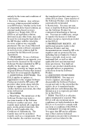
...an external media-based recovery solution (e.g. You agree that formed the basis for the original Software Product identified by HP or its affiliates may not reverse engineer, decompile, or disassemble the Software Product, except and only to the extent that the right to all component parts, media, printed ...materials, this EULA or if you fail to the original Software Product provided by the terms and conditions of the HP Product with/for which...
...an external media-based recovery solution (e.g. You agree that formed the basis for the original Software Product identified by HP or its affiliates may not reverse engineer, decompile, or disassemble the Software Product, except and only to the extent that the right to all component parts, media, printed ...materials, this EULA or if you fail to the original Software Product provided by the terms and conditions of the HP Product with/for which...

Power
Page 43
... Power or dispose of a stored battery pack, place it to temperatures above 60°C (140°F). Refer to a battery pack, do not disassemble, crush, or puncture a battery pack; Battery packs Storing a battery pack Å WARNING: To avoid potential safety issues, only the battery pack... provided with the computer, a replacement battery pack provided by HP, or a compatible battery pack purchased as an accessory from external power for more . short the external contacts on a battery pack; To ...
... Power or dispose of a stored battery pack, place it to temperatures above 60°C (140°F). Refer to a battery pack, do not disassemble, crush, or puncture a battery pack; Battery packs Storing a battery pack Å WARNING: To avoid potential safety issues, only the battery pack... provided with the computer, a replacement battery pack provided by HP, or a compatible battery pack purchased as an accessory from external power for more . short the external contacts on a battery pack; To ...
Maintenance and Service Guide
Page 1
It provides comprehensive information on identifying computer features, components, and spare parts; and performing computer disassembly procedures. troubleshooting computer problems; Maintenance and Service Guide HP Compaq nc6300 Notebook PC HP Compaq nx6300 Notebook PC Document Part Number: 415793-002 November 2006 This guide is a troubleshooting reference used for maintaining and servicing the computer.
It provides comprehensive information on identifying computer features, components, and spare parts; and performing computer disassembly procedures. troubleshooting computer problems; Maintenance and Service Guide HP Compaq nc6300 Notebook PC HP Compaq nx6300 Notebook PC Document Part Number: 415793-002 November 2006 This guide is a troubleshooting reference used for maintaining and servicing the computer.

Maintenance and Service Guide
Page 11
...; Lid switch standby/resume ■ Power button ■ Advanced Configuration and Power Management (ACPM) compliance Maintenance and Service Guide 1-5 Product Description 1. Prepare the computer for disassembly (refer to the computer. Replace the RTC battery and reassemble the computer. 4. Connect AC power to Section 5.3, "Preparing the Computer for...
...; Lid switch standby/resume ■ Power button ■ Advanced Configuration and Power Management (ACPM) compliance Maintenance and Service Guide 1-5 Product Description 1. Prepare the computer for disassembly (refer to the computer. Replace the RTC battery and reassemble the computer. 4. Connect AC power to Section 5.3, "Preparing the Computer for...

Maintenance and Service Guide
Page 28
... controlled by high external temperatures, system power consumption, power management/battery conservation configurations, battery fast charging, and software. The computer uses an electric fan for disassembly steps. These conditions are affected by a temperature sensor and is displaced through the ventilation grill located on the left and right sides of the computer...
... controlled by high external temperatures, system power consumption, power management/battery conservation configurations, battery fast charging, and software. The computer uses an electric fan for disassembly steps. These conditions are affected by a temperature sensor and is displaced through the ventilation grill located on the left and right sides of the computer...

Maintenance and Service Guide
Page 96
...Guide Cables must be caught or snagged by the connector whenever possible. Be sure that cables are placed in their proper locations during disassembly and reassembly can damage the computer. Apply only the tension required to avoid damage. Removal and Replacement Preliminaries 4.2 Service Considerations The following... sections include some of the considerations that you should keep in mind during disassembly and assembly procedures. ✎ As you remove each subassembly from the work area to prevent damage.
...Guide Cables must be caught or snagged by the connector whenever possible. Be sure that cables are placed in their proper locations during disassembly and reassembly can damage the computer. Apply only the tension required to avoid damage. Removal and Replacement Preliminaries 4.2 Service Considerations The following... sections include some of the considerations that you should keep in mind during disassembly and assembly procedures. ✎ As you remove each subassembly from the work area to prevent damage.

Maintenance and Service Guide
Page 105
...Service Guide 5-3 Optical Drive 1 to remove the optical drive 2 to restore computer functionality. Removal and Replacement Procedures 5.2 Disassembly Sequence Chart Use the chart below to determine the section number to remove the memory/Mini Card module cover Mini Card WLAN... agency that regulates wireless devices in your country. Section 5.3 5.4 5.5 5.6 5.7 5.8 5.9 Disassembly Sequence Chart Description # of a warning message, replace with only a Mini Card device authorized for Disassembly Battery 0 Hard Drive 2 loosened to remove the hard drive cover 1 loosened to remove the...
...Service Guide 5-3 Optical Drive 1 to remove the optical drive 2 to restore computer functionality. Removal and Replacement Procedures 5.2 Disassembly Sequence Chart Use the chart below to determine the section number to remove the memory/Mini Card module cover Mini Card WLAN... agency that regulates wireless devices in your country. Section 5.3 5.4 5.5 5.6 5.7 5.8 5.9 Disassembly Sequence Chart Description # of a warning message, replace with only a Mini Card device authorized for Disassembly Battery 0 Hard Drive 2 loosened to remove the hard drive cover 1 loosened to remove the...

Maintenance and Service Guide
Page 106
Removal and Replacement Procedures Disassembly Sequence Chart (Continued) Section 5.10 5.11 5.12 5.13 5.14 5.15 5.16 5.17 5.18 5.19 5.20 5.21 5.22 5.23 5.24 5.25 Description # of Screws Removed Keyboard 2 ...
Removal and Replacement Procedures Disassembly Sequence Chart (Continued) Section 5.10 5.11 5.12 5.13 5.14 5.15 5.16 5.17 5.18 5.19 5.20 5.21 5.22 5.23 5.24 5.25 Description # of Screws Removed Keyboard 2 ...

Maintenance and Service Guide
Page 107
Removal and Replacement Procedures 5.3 Preparing the Computer for Disassembly Before you are unsure whether the computer is off or in hibernation, turn the computer on, and then shut it down the computer. Maintenance and Service Guide 5-5 Shut down through the operating system. 2. If you begin any removal or installation procedures: 1. Disconnect the power cord. Disconnect all external devices connected to the computer. 3.
Removal and Replacement Procedures 5.3 Preparing the Computer for Disassembly Before you are unsure whether the computer is off or in hibernation, turn the computer on, and then shut it down the computer. Maintenance and Service Guide 5-5 Shut down through the operating system. 2. If you begin any removal or installation procedures: 1. Disconnect the power cord. Disconnect all external devices connected to the computer. 3.

Maintenance and Service Guide
Page 109
Prepare the computer for disassembly (refer to Section 5.3). 2. Maintenance and Service Guide 5-7 Position the computer with the front toward you. 5.4 Hard Drive Removal and Replacement Procedures Hard Drive Spare Part Number Information 7200-rpm, 60-GB 413854-001 5400-rpm, 100-GB 5400-rpm, 80-GB 5400-rpm, 60-GB 5400-rpm, 40-GB 413853-001 413852-001 413851-001 413850-001 1.
Prepare the computer for disassembly (refer to Section 5.3). 2. Maintenance and Service Guide 5-7 Position the computer with the front toward you. 5.4 Hard Drive Removal and Replacement Procedures Hard Drive Spare Part Number Information 7200-rpm, 60-GB 413854-001 5400-rpm, 100-GB 5400-rpm, 80-GB 5400-rpm, 60-GB 5400-rpm, 40-GB 413853-001 413852-001 413851-001 413850-001 1.

Maintenance and Service Guide
Page 114
Prepare the computer for disassembly (refer to install a Bluetooth module. 5-12 Maintenance and Service Guide Slide the Bluetooth module 1 out of the clip in the hard drive compartment. 4. Remove the hard drive (Section 5.4). 3. Disconnect the Bluetooth cable 2 from the module. Removal and Replacement Procedures 5.6 Bluetooth Module Bluetooth Module Spare Part Number Information Bluetooth module (includes Bluetooth cable) 398393-001 1. Removing the Bluetooth Module Reverse the above procedure to Section 5.3). 2.
Prepare the computer for disassembly (refer to install a Bluetooth module. 5-12 Maintenance and Service Guide Slide the Bluetooth module 1 out of the clip in the hard drive compartment. 4. Remove the hard drive (Section 5.4). 3. Disconnect the Bluetooth cable 2 from the module. Removal and Replacement Procedures 5.6 Bluetooth Module Bluetooth Module Spare Part Number Information Bluetooth module (includes Bluetooth cable) 398393-001 1. Removing the Bluetooth Module Reverse the above procedure to Section 5.3). 2.

Maintenance and Service Guide
Page 115
Prepare the computer for disassembly (refer to Section 5.3). 2. Position the computer with the front toward you. Maintenance and Service Guide 5-13 Removal and Replacement Procedures 5.7 External Memory Module Memory Module Spare Part Number Information PC2-5300 1024-MB 512-MB 256-MB 414046-001 414045-001 414044-001 PC2-4200 1024-MB 512-MB 256-MB 414042-001 414041-001 414040-001 1.
Prepare the computer for disassembly (refer to Section 5.3). 2. Position the computer with the front toward you. Maintenance and Service Guide 5-13 Removal and Replacement Procedures 5.7 External Memory Module Memory Module Spare Part Number Information PC2-5300 1024-MB 512-MB 256-MB 414046-001 414045-001 414044-001 PC2-4200 1024-MB 512-MB 256-MB 414042-001 414041-001 414040-001 1.

Maintenance and Service Guide
Page 120
... for use in the United States and Canada. 802.11a/b/g HS WLAN module for use in the MOW 2 countries listed below. Prepare the computer for disassembly (Section 5.3). 2. Remove the memory/Mini Card module cover (Section 5.7). 3.
... for use in the United States and Canada. 802.11a/b/g HS WLAN module for use in the MOW 2 countries listed below. Prepare the computer for disassembly (Section 5.3). 2. Remove the memory/Mini Card module cover (Section 5.7). 3.

Maintenance and Service Guide
Page 122
Remove the memory/Mini Card module cover (Section 5.7). 3. Prepare the computer for disassembly (Section 5.3). 2. Position the computer with the right side toward you. 5-20 Maintenance and Service Guide Removal and Replacement Procedures 5.9 Optical Drive Optical Drive Spare Part Number Information 24X Max CD-ROM drive 8X Max DVD-ROM drive 4X Max DVD±RW and CD-RW Combo Drive 8X Max DVD±RW and CD-RW Combo Drive 24X Max DVD/CD-RW Combo Drive 413698-001 413699-001 413700-001 413702-001 413701-101 1.
Remove the memory/Mini Card module cover (Section 5.7). 3. Prepare the computer for disassembly (Section 5.3). 2. Position the computer with the right side toward you. 5-20 Maintenance and Service Guide Removal and Replacement Procedures 5.9 Optical Drive Optical Drive Spare Part Number Information 24X Max CD-ROM drive 8X Max DVD-ROM drive 4X Max DVD±RW and CD-RW Combo Drive 8X Max DVD±RW and CD-RW Combo Drive 24X Max DVD/CD-RW Combo Drive 413698-001 413699-001 413700-001 413702-001 413701-101 1.

Maintenance and Service Guide
Page 126
Prepare the computer for disassembly (Section 5.3). 2. Remove the memory/Mini Card module cover (Section 5.7). 5-24 Maintenance and Service Guide Removal and Replacement Procedures Keyboard Spare Part Number Information (Continued) Keyboards (...
Prepare the computer for disassembly (Section 5.3). 2. Remove the memory/Mini Card module cover (Section 5.7). 5-24 Maintenance and Service Guide Removal and Replacement Procedures Keyboard Spare Part Number Information (Continued) Keyboards (...

Maintenance and Service Guide
Page 131
Prepare the computer for disassembly (Section 5.3). 2. Remove the fan 3. Removing the Fan Reverse the above procedure to the computer. 5. Maintenance and Service Guide 5-29 Loosen the two Phillips PM2.0×7.0 screws 2 that secure the fan to install the fan. 5.11 Fan Removal and Replacement Procedures Fan Spare Part Number Information Fan 379799-001 1. Release the keyboard (Section 5.10). 3. Disconnect the fan cable 1 from the system board. 4.
Prepare the computer for disassembly (Section 5.3). 2. Remove the fan 3. Removing the Fan Reverse the above procedure to the computer. 5. Maintenance and Service Guide 5-29 Loosen the two Phillips PM2.0×7.0 screws 2 that secure the fan to install the fan. 5.11 Fan Removal and Replacement Procedures Fan Spare Part Number Information Fan 379799-001 1. Release the keyboard (Section 5.10). 3. Disconnect the fan cable 1 from the system board. 4.

Maintenance and Service Guide
Page 132
Remove the fan (Section 5.11). 5-30 Maintenance and Service Guide Release the keyboard (Section 5.10). 3. Prepare the computer for disassembly (Section 5.3). 2. Removal and Replacement Procedures 5.12 Heat Sink Heat Sink Spare Part Number Information Heat sink (includes thermal paste) Thermal Grease Kit (not illustrated) 379799-001 413706-001 1.
Remove the fan (Section 5.11). 5-30 Maintenance and Service Guide Release the keyboard (Section 5.10). 3. Prepare the computer for disassembly (Section 5.3). 2. Removal and Replacement Procedures 5.12 Heat Sink Heat Sink Spare Part Number Information Heat sink (includes thermal paste) Thermal Grease Kit (not illustrated) 379799-001 413706-001 1.

Maintenance and Service Guide
Page 135
Remove the heat sink (Section 5.12). Release the keyboard (Section 5.10). 3. Prepare the computer for disassembly (Section 5.3). 2. Remove the fan (Section 5.11). 4. 5.13 Processor Removal and Replacement Procedures Processor Spare Part Number Information Intel Core Duo T2600 (2.16-GHz) processor Intel ...
Remove the heat sink (Section 5.12). Release the keyboard (Section 5.10). 3. Prepare the computer for disassembly (Section 5.3). 2. Remove the fan (Section 5.11). 4. 5.13 Processor Removal and Replacement Procedures Processor Spare Part Number Information Intel Core Duo T2600 (2.16-GHz) processor Intel ...

Maintenance and Service Guide
Page 137
Removing the RTC Battery Reverse the above procedure to install an RTC battery. Disconnect the RTC battery cable 1 from the clip in the Plastics Kit, spare part number 413704-001. 1. Removal and Replacement Procedures 5.14 RTC Battery ✎ The RTC battery is included in the top cover. Prepare the computer for disassembly (Section 5.3). 2. Maintenance and Service Guide 5-35 Remove the RTC battery 2 from the system board. 4. Release the keyboard (Section 5.10). 3.
Removing the RTC Battery Reverse the above procedure to install an RTC battery. Disconnect the RTC battery cable 1 from the clip in the Plastics Kit, spare part number 413704-001. 1. Removal and Replacement Procedures 5.14 RTC Battery ✎ The RTC battery is included in the top cover. Prepare the computer for disassembly (Section 5.3). 2. Maintenance and Service Guide 5-35 Remove the RTC battery 2 from the system board. 4. Release the keyboard (Section 5.10). 3.

Maintenance and Service Guide
Page 138
Release the keyboard (Section 5.10). 5-36 Maintenance and Service Guide Removal and Replacement Procedures 5.15 Internal Memory Module Memory Module Spare Part Number Information 1024 MB 512 MB 336579-001 336578-001 1. Prepare the computer for disassembly (Section 5.3). 2.
Release the keyboard (Section 5.10). 5-36 Maintenance and Service Guide Removal and Replacement Procedures 5.15 Internal Memory Module Memory Module Spare Part Number Information 1024 MB 512 MB 336579-001 336578-001 1. Prepare the computer for disassembly (Section 5.3). 2.


