Getting Started - Windows 7
Page 6
... hard drive ...42 Removing the hard drive ...42 Installing a hard drive ...42 Replacing the memory module ...44 Updating programs and drivers ...46 Routine care ...46 Cleaning the display ...46 Cleaning the TouchPad and keyboard 46 7 Backup and recovery ...47 Recovery discs ...48 Performing a system recovery ...48 Recovery using the dedicated recovery partition...
... hard drive ...42 Removing the hard drive ...42 Installing a hard drive ...42 Replacing the memory module ...44 Updating programs and drivers ...46 Routine care ...46 Cleaning the display ...46 Cleaning the TouchPad and keyboard 46 7 Backup and recovery ...47 Recovery discs ...48 Performing a system recovery ...48 Recovery using the dedicated recovery partition...

Getting Started - Windows 7
Page 66
... settings 50 personal files 50 battery bay 13, 54 battery light, identifying 11 battery locking latch 13 battery release latch 13 battery, replacing 38 Bluetooth label 54 buttons left TouchPad 5 right TouchPad 5 C caps lock light, identifying 6 care of the computer 46 Certificate of...(microphone) 11 audio-out (headphone) 11 network 10 RJ-45 (network) 10 K keyboard hotkey, identifying 29 keyboard, using 29 keys action 7 esc 7 fn 7 Windows applications 7 Windows logo 7 L labels Bluetooth 54 HP Mobile Broadband Module 54 Microsoft Certificate of Authenticity 54 regulatory 54 serial number 54 SIM 54...
... settings 50 personal files 50 battery bay 13, 54 battery light, identifying 11 battery locking latch 13 battery release latch 13 battery, replacing 38 Bluetooth label 54 buttons left TouchPad 5 right TouchPad 5 C caps lock light, identifying 6 care of the computer 46 Certificate of...(microphone) 11 audio-out (headphone) 11 network 10 RJ-45 (network) 10 K keyboard hotkey, identifying 29 keyboard, using 29 keys action 7 esc 7 fn 7 Windows applications 7 Windows logo 7 L labels Bluetooth 54 HP Mobile Broadband Module 54 Microsoft Certificate of Authenticity 54 regulatory 54 serial number 54 SIM 54...
HP Mini 210 - Maintenance and Service Guide
Page 8
Component replacement procedures 32 Computer feet ...32 Battery ...33 SIM ...35 Service access cover ...36 Hard drive ...39 WWAN and GPS modules (select models only 42 WLAN module ...44 Memory module ...46 RTC battery ...47 Keyboard ...48 Top cover ...51 Speakers ...55 Display assembly ...57 Fan/heat sink assembly ...61 System board ...63...
Component replacement procedures 32 Computer feet ...32 Battery ...33 SIM ...35 Service access cover ...36 Hard drive ...39 WWAN and GPS modules (select models only 42 WLAN module ...44 Memory module ...46 RTC battery ...47 Keyboard ...48 Top cover ...51 Speakers ...55 Display assembly ...57 Fan/heat sink assembly ...61 System board ...63...
HP Mini 210 - Maintenance and Service Guide
Page 33
...001 622344-031 622344-041 622344-051 622344-061 Description Broadcom GPS Mini Card (select models only) Base enclosure (includes 4 rubber feet and power connector bracket) Power connector cable Fan/heat sink assembly (includes replacement thermal material) 25.7-cm (10.1-in) WSVGA, flush glass ...), and webcam/microphone module and cable) Keyboard for use in the United States (includes cable) Keyboard for use in the United Kingdom and Singapore (includes cable) Keyboard for use in Germany (includes cable) Keyboard for use in France (includes cable) Keyboard for use in Italy (includes cable) ...
...001 622344-031 622344-041 622344-051 622344-061 Description Broadcom GPS Mini Card (select models only) Base enclosure (includes 4 rubber feet and power connector bracket) Power connector cable Fan/heat sink assembly (includes replacement thermal material) 25.7-cm (10.1-in) WSVGA, flush glass ...), and webcam/microphone module and cable) Keyboard for use in the United States (includes cable) Keyboard for use in the United Kingdom and Singapore (includes cable) Keyboard for use in Germany (includes cable) Keyboard for use in France (includes cable) Keyboard for use in Italy (includes cable) ...

HP Mini 210 - Maintenance and Service Guide
Page 58
... number 622344-B31 622344-131 622344-251 622344-171 622344-BA1 622344-AD1 622344-071 622344-BG1 622344-AB1 622344-281 48 Chapter 4 Removal and replacement procedures Keyboard NOTE: The keyboard spare part kit includes a keyboard cable. 2. Remove the RTC battery (2) from the computer.
... number 622344-B31 622344-131 622344-251 622344-171 622344-BA1 622344-AD1 622344-071 622344-BG1 622344-AB1 622344-281 48 Chapter 4 Removal and replacement procedures Keyboard NOTE: The keyboard spare part kit includes a keyboard cable. 2. Remove the RTC battery (2) from the computer.

HP Mini 210 - Maintenance and Service Guide
Page 59
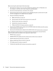
... and then shut it down the computer. Disconnect all external devices connected to the computer. 2. Remove the following components: a. Component replacement procedures 49 Battery (see Service access cover on page 33). Turn the computer right-side up, with the front toward you are ...1. Service access cover (see Battery on page 36). Shut down through the operating system. 2. Remove the keyboard: 1. Remove the 3 Phillips 2.0×5.0 screws that secure the keyboard to the computer. 3. Disconnect the power from the computer by first unplugging the power cord from the AC ...
... and then shut it down the computer. Disconnect all external devices connected to the computer. 2. Remove the following components: a. Component replacement procedures 49 Battery (see Service access cover on page 33). Turn the computer right-side up, with the front toward you are ...1. Service access cover (see Battery on page 36). Shut down through the operating system. 2. Remove the keyboard: 1. Remove the 3 Phillips 2.0×5.0 screws that secure the keyboard to the computer. 3. Disconnect the power from the computer by first unplugging the power cord from the AC ...
HP Mini 210 - Maintenance and Service Guide
Page 60
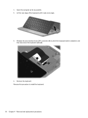
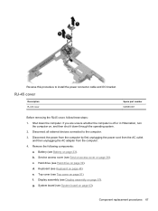
Reverse this procedure to which the keyboard cable is attached, and then disconnect the keyboard cable (2) 6. Release the zero insertion force (ZIF) connector (1) to install the keyboard. 50 Chapter 4 Removal and replacement procedures Lift the rear edge of the keyboard until it rests at an angle. 5. 3. Open the computer as far as possible. 4. Remove the keyboard.
Reverse this procedure to which the keyboard cable is attached, and then disconnect the keyboard cable (2) 6. Release the zero insertion force (ZIF) connector (1) to install the keyboard. 50 Chapter 4 Removal and replacement procedures Lift the rear edge of the keyboard until it rests at an angle. 5. 3. Open the computer as far as possible. 4. Remove the keyboard.
HP Mini 210 - Maintenance and Service Guide
Page 61
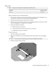
...Battery on page 36). If you are unsure whether the computer is off or in Hibernation, turn the computer on page 48). Keyboard (see Keyboard on , and then shut it down the computer. Shut down through the operating system. 2. Remove the 2 Phillips 2.0×2.5 screws... Remove the following components: a. Disconnect all external devices connected to the display hinges. b. Remove the interior hinge covers (2). Component replacement procedures 51 Top cover NOTE: The top cover includes the TouchPad and TouchPad cable. Description Top cover Spare part number 635012-001 Before...
...Battery on page 36). If you are unsure whether the computer is off or in Hibernation, turn the computer on page 48). Keyboard (see Keyboard on , and then shut it down the computer. Shut down through the operating system. 2. Remove the 2 Phillips 2.0×2.5 screws... Remove the following components: a. Disconnect all external devices connected to the display hinges. b. Remove the interior hinge covers (2). Component replacement procedures 51 Top cover NOTE: The top cover includes the TouchPad and TouchPad cable. Description Top cover Spare part number 635012-001 Before...
HP Mini 210 - Maintenance and Service Guide
Page 65
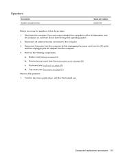
... page 51). Turn the top cover upside down through the operating system. 2. b. d. Component replacement procedures 55 Battery (see Top cover on page 33). Keyboard (see Service access cover on page 48). Remove the following components: a. Service access cover (see Keyboard on page 36). Remove the speakers: 1. c. If you are unsure whether the computer...
... page 51). Turn the top cover upside down through the operating system. 2. b. d. Component replacement procedures 55 Battery (see Top cover on page 33). Keyboard (see Service access cover on page 48). Remove the following components: a. Service access cover (see Keyboard on page 36). Remove the speakers: 1. c. If you are unsure whether the computer...
HP Mini 210 - Maintenance and Service Guide
Page 67
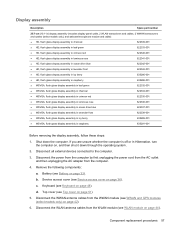
... by first unplugging the power cord from the AC outlet and then unplugging the AC adapter from the WLAN module (see Keyboard on page 36). b. Keyboard (see WLAN module on page 44). If you are unsure whether the computer is off or in raspberry 635291-001 Before... cables from the computer. 4. Service access cover (see Top cover on page 33). Top cover (see Service access cover on page 48). Component replacement procedures 57 Display assembly Description Spare part number 25.7-cm (10.1-in) display assembly (includes display panel cable, 2 WLAN transceivers and cables, 2 ...
... by first unplugging the power cord from the AC outlet and then unplugging the AC adapter from the WLAN module (see Keyboard on page 36). b. Keyboard (see WLAN module on page 44). If you are unsure whether the computer is off or in raspberry 635291-001 Before... cables from the computer. 4. Service access cover (see Top cover on page 33). Top cover (see Service access cover on page 48). Component replacement procedures 57 Display assembly Description Spare part number 25.7-cm (10.1-in) display assembly (includes display panel cable, 2 WLAN transceivers and cables, 2 ...
HP Mini 210 - Maintenance and Service Guide
Page 74
... Fan/heat sink assembly on page 61) 64 Chapter 4 Removal and replacement procedures Battery (see Hard drive on page 57). 5. b. e. When replacing the system board, be sure that the following components: a. Hard drive (see Battery on page 36). d. Display assembly (see Keyboard on page 42). 6. Shut down through the operating system. 2. If you...
... Fan/heat sink assembly on page 61) 64 Chapter 4 Removal and replacement procedures Battery (see Hard drive on page 57). 5. b. e. When replacing the system board, be sure that the following components: a. Hard drive (see Battery on page 36). d. Display assembly (see Keyboard on page 42). 6. Shut down through the operating system. 2. If you...

HP Mini 210 - Maintenance and Service Guide
Page 76
... computer is off or in Hibernation, turn the computer on page 36). Remove the following components: a. Keyboard (see Service access cover on , and then shut it up off the base enclosure. 66 Chapter 4 Removal and replacement procedures Service access cover (see Keyboard on page 39). e. Disconnect all external devices connected to the computer. 3.
... computer is off or in Hibernation, turn the computer on page 36). Remove the following components: a. Keyboard (see Service access cover on , and then shut it up off the base enclosure. 66 Chapter 4 Removal and replacement procedures Service access cover (see Keyboard on page 39). e. Disconnect all external devices connected to the computer. 3.
HP Mini 210 - Maintenance and Service Guide
Page 77
If you are unsure whether the computer is off or in Hibernation, turn the computer on page 63). f. Component replacement procedures 67 Remove the following components: a. Service access cover (see Service access cover on page 57). c. Display assembly (see Battery on page... 48). Shut down through the operating system. 2. Battery (see Display assembly on page 36). Keyboard (see Top cover on page 39). d. Top cover (see Keyboard on page 33). Hard drive (see System board on , and then shut it down the computer. Reverse this procedure to...
If you are unsure whether the computer is off or in Hibernation, turn the computer on page 63). f. Component replacement procedures 67 Remove the following components: a. Service access cover (see Service access cover on page 57). c. Display assembly (see Battery on page... 48). Shut down through the operating system. 2. Battery (see Display assembly on page 36). Keyboard (see Top cover on page 39). d. Top cover (see Keyboard on page 33). Hard drive (see System board on , and then shut it down the computer. Reverse this procedure to...
HP Mini 210 - Maintenance and Service Guide
Page 108
...microphones, identifying 11 J jacks audio-in (microphone) 11 audio-out (headphone) 11 network 10 RJ-45 (network) 10 K keyboard product description 3 removal 48 spare part numbers 16, 23, 24, 48 keys action 8 esc 8 fn 8 Windows applications 8..., identifying 9 processor, product description 1 product description audio 2 chipset 1 display 1 Ethernet 2 external media cards 3 graphics 1 hard drive 2 internal media cards 3 keyboard 3 memory module 1 modem 2 operating system 4 optical drive 2 pointing device 3 ports 3 power requirements 3 processors 1 product name 1 security 3 serviceability 4 video ...
...microphones, identifying 11 J jacks audio-in (microphone) 11 audio-out (headphone) 11 network 10 RJ-45 (network) 10 K keyboard product description 3 removal 48 spare part numbers 16, 23, 24, 48 keys action 8 esc 8 fn 8 Windows applications 8..., identifying 9 processor, product description 1 product description audio 2 chipset 1 display 1 Ethernet 2 external media cards 3 graphics 1 hard drive 2 internal media cards 3 keyboard 3 memory module 1 modem 2 operating system 4 optical drive 2 pointing device 3 ports 3 power requirements 3 processors 1 product name 1 security 3 serviceability 4 video ...


