
Service Manual
Page 8
...116 Stapler ...117 Stapler power-supply ...123 Right-side fan ...128 Engine control unit (ECU) ...131 Left-side riser ...138 Fuser ...139 Laser/scanner ...142 Access plate ...144 Oblique-roller assembly ...146 Left-side fan ...148 High-voltage power supply (HVPS 149 Feed-guide assembly ...156... Main motor ...159 Gear assembly ...162 Reinstallation notes for the gear assembly 165 Tray 1 solenoid ...166 Tray 2 solenoid ...167 Pickup assembly ...168 Tray 1 media-present sensor and top-of ...
...116 Stapler ...117 Stapler power-supply ...123 Right-side fan ...128 Engine control unit (ECU) ...131 Left-side riser ...138 Fuser ...139 Laser/scanner ...142 Access plate ...144 Oblique-roller assembly ...146 Left-side fan ...148 High-voltage power supply (HVPS 149 Feed-guide assembly ...156... Main motor ...159 Gear assembly ...162 Reinstallation notes for the gear assembly 165 Tray 1 solenoid ...166 Tray 2 solenoid ...167 Pickup assembly ...168 Tray 1 media-present sensor and top-of ...
Service Manual
Page 87
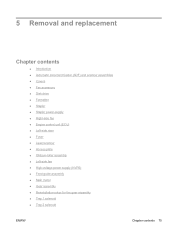
... drive ● Formatter ● Stapler ● Stapler power-supply ● Right-side fan ● Engine control unit (ECU) ● Left-side riser ● Fuser ● Laser/scanner ● Access plate ● Oblique-roller assembly ● Left-side fan ● High-voltage power supply (HVPS) ● Feed-guide assembly ● Main motor...
... drive ● Formatter ● Stapler ● Stapler power-supply ● Right-side fan ● Engine control unit (ECU) ● Left-side riser ● Fuser ● Laser/scanner ● Access plate ● Oblique-roller assembly ● Left-side fan ● High-voltage power supply (HVPS) ● Feed-guide assembly ● Main motor...
Service Manual
Page 91
... accessory Disk drive Formatter Stapler power-supply Front, right cover Right-side fan Cartridge door All covers and the ADF/scanner assembly Left-side riser Laser/scanner E-label reader Face-down-roller shaft Left-side fan Fax accessory Disk drive Formatter Stapler Stapler power-supply Right-side fan ECU Tray 1 solenoid... Left-side riser Access plate Oblique-roller assembly Left-side fan High-voltage power supply (HVPS) Feed-guide assembly Main motor Gear assembly Tray 2 solenoid Pickup assembly Tray 1 media-present sensor Top-of the section.
... accessory Disk drive Formatter Stapler power-supply Front, right cover Right-side fan Cartridge door All covers and the ADF/scanner assembly Left-side riser Laser/scanner E-label reader Face-down-roller shaft Left-side fan Fax accessory Disk drive Formatter Stapler Stapler power-supply Right-side fan ECU Tray 1 solenoid... Left-side riser Access plate Oblique-roller assembly Left-side fan High-voltage power supply (HVPS) Feed-guide assembly Main motor Gear assembly Tray 2 solenoid Pickup assembly Tray 1 media-present sensor Top-of the section.
Service Manual
Page 159
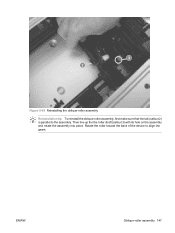
3 2 Figure 5-69 Reinstalling the oblique-roller assembly Reinstallation tip To reinstall the oblique-roller assembly, first make sure that the tab (callout 2) is parallel to align the gears. Rotate the roller toward the back of the device to the assembly. ENWW Oblique-roller assembly 147 Then line up the the roller shaft (callout 3) with its hole on the assembly and rotate the assembly into place.
3 2 Figure 5-69 Reinstalling the oblique-roller assembly Reinstallation tip To reinstall the oblique-roller assembly, first make sure that the tab (callout 2) is parallel to align the gears. Rotate the roller toward the back of the device to the assembly. ENWW Oblique-roller assembly 147 Then line up the the roller shaft (callout 3) with its hole on the assembly and rotate the assembly into place.
Service Manual
Page 174
... 148) Tip You do not have to unroute the left-side-fan cable in order to remove the HVPS, the feed-guide assembly, or the gear assembly. Gear assembly 1.
... 148) Tip You do not have to unroute the left-side-fan cable in order to remove the HVPS, the feed-guide assembly, or the gear assembly. Gear assembly 1.
Service Manual
Page 175
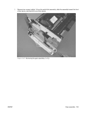
Remove two screws (callout 1) from the switch-link assembly, slide the assembly toward the front of the device, and then lift it out of the device. 1 Figure 5-81 Removing the gear assembly (1 of 2) ENWW Gear assembly 163 2.
Remove two screws (callout 1) from the switch-link assembly, slide the assembly toward the front of the device, and then lift it out of the device. 1 Figure 5-81 Removing the gear assembly (1 of 2) ENWW Gear assembly 163 2.
Service Manual
Page 176
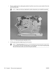
... plate. NOTE Make sure that you duplicate the cable routing when you reinstall the assembly. 3 3 2 Figure 5-82 Removing the gear assembly (2 of the device when you remove the gear assembly. 164 Chapter 5 Removal and replacement ENWW Remove cables from four cable guides (callout 2) and then remove four screws (callout 3) from the device...
... plate. NOTE Make sure that you duplicate the cable routing when you reinstall the assembly. 3 3 2 Figure 5-82 Removing the gear assembly (2 of the device when you remove the gear assembly. 164 Chapter 5 Removal and replacement ENWW Remove cables from four cable guides (callout 2) and then remove four screws (callout 3) from the device...
Service Manual
Page 177
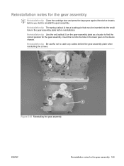
.... Insert the rod into the small hole in the lower gear on the gear-assembly plate as a locator to catch any cables behind the gear-assembly plate when reinstalling the screws. 5 4 Figure 5-83 Reinstalling the gear assembly ENWW Reinstallation notes for the gear assembly 165 Reinstallation tip Use the rod (callout 5) on the device chassis...
.... Insert the rod into the small hole in the lower gear on the gear-assembly plate as a locator to catch any cables behind the gear-assembly plate when reinstalling the screws. 5 4 Figure 5-83 Reinstalling the gear assembly ENWW Reinstallation notes for the gear assembly 165 Reinstallation tip Use the rod (callout 5) on the device chassis...
Service Manual
Page 179
...) ● ECU (see Engine control unit (ECU) on page 131) ● High-voltage power supply (see High-voltage power supply (HVPS) on page 149) ● Gear assembly (see Gear assembly on page 162) 2.
...) ● ECU (see Engine control unit (ECU) on page 131) ● High-voltage power supply (see High-voltage power supply (HVPS) on page 149) ● Gear assembly (see Gear assembly on page 162) 2.
Service Manual
Page 180
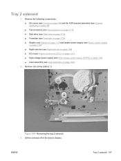
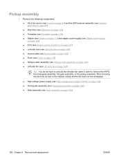
...; High-voltage power supply (see High-voltage power supply (HVPS) on page 149) ● Feed-guide assembly (see Feed-guide assembly on page 156) ● Gear assembly (see Left-side fan on page 148) Tip You do not have to remove the HVPS, the feed-guide assembly, the... gear assembly, or the pickup assembly. Remove the following components: ● All of the covers (see Covers on page 94) and the ADF/scanner assembly (see ...
...; High-voltage power supply (see High-voltage power supply (HVPS) on page 149) ● Feed-guide assembly (see Feed-guide assembly on page 156) ● Gear assembly (see Left-side fan on page 148) Tip You do not have to remove the HVPS, the feed-guide assembly, the... gear assembly, or the pickup assembly. Remove the following components: ● All of the covers (see Covers on page 94) and the ADF/scanner assembly (see ...
Service Manual
Page 181
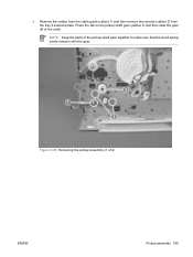
2. NOTE Keep the parts of the pickup-shaft gear together to make sure that the small spring inside remains with the gear. 3 1 2 Figure 5-86 Removing the pickup assembly (1 of the shaft. Press the tab on the pickup shaft gear (callout 3) and then slide the gear off of 4) ENWW Pickup assembly 169 Remove the cables from the cable guide (callout 1) and then remove two screws (callout 2) from the tray 2 solenoid plate.
2. NOTE Keep the parts of the pickup-shaft gear together to make sure that the small spring inside remains with the gear. 3 1 2 Figure 5-86 Removing the pickup assembly (1 of the shaft. Press the tab on the pickup shaft gear (callout 3) and then slide the gear off of 4) ENWW Pickup assembly 169 Remove the cables from the cable guide (callout 1) and then remove two screws (callout 2) from the tray 2 solenoid plate.
Service Manual
Page 184
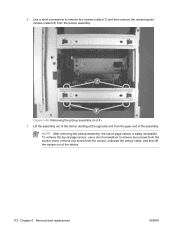
... (4 of the device. 172 Chapter 5 Removal and replacement ENWW 6. Use a short screwdriver to remove two screws from the sensor cover, remove one screw from the gear-end of -page sensor is easily accessible.
... (4 of the device. 172 Chapter 5 Removal and replacement ENWW 6. Use a short screwdriver to remove two screws from the sensor cover, remove one screw from the gear-end of -page sensor is easily accessible.
Service Manual
Page 194
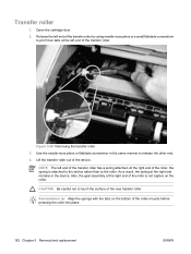
... on the roller. NOTE The left end of the roller-mounts before pressing the roller into place. 182 Chapter 5 Removal and replacement ENWW Also, the gear assembly at the right end remains in the same manner to the roller. Open the cartridge door. 2. Figure 5-99 Removing the transfer roller 3. CAUTION Be...
... on the roller. NOTE The left end of the roller-mounts before pressing the roller into place. 182 Chapter 5 Removal and replacement ENWW Also, the gear assembly at the right end remains in the same manner to the roller. Open the cartridge door. 2. Figure 5-99 Removing the transfer roller 3. CAUTION Be...
Service Manual
Page 195
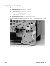
Registration assembly 1. Unhook the clasp on page 90) 2. Remove the following components: ● Right-side cover (see Right-side cover on page 94) ● Formatter shield (see Formatter shield on page 95) ● Fax cover (see Fax cover on page 96) ● Left-side cover (see Left-side cover on page 97) ● ADF/scanner assembly (see Scanner assembly on the registration assembly gear (callout 1), and then slide the gear off of the shaft. 1 Figure 5-100 Removing the registration assembly (1 of 3) ENWW Registration assembly 183
Registration assembly 1. Unhook the clasp on page 90) 2. Remove the following components: ● Right-side cover (see Right-side cover on page 94) ● Formatter shield (see Formatter shield on page 95) ● Fax cover (see Fax cover on page 96) ● Left-side cover (see Left-side cover on page 97) ● ADF/scanner assembly (see Scanner assembly on the registration assembly gear (callout 1), and then slide the gear off of the shaft. 1 Figure 5-100 Removing the registration assembly (1 of 3) ENWW Registration assembly 183
Service Manual
Page 197
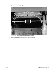
Lift the registration assembly out of 3) 5. ENWW Registration assembly 185 Remove four screws (callout 3). Figure 5-102 Removing the registration assembly (3 of the device, gear-end first. 4.
Lift the registration assembly out of 3) 5. ENWW Registration assembly 185 Remove four screws (callout 3). Figure 5-102 Removing the registration assembly (3 of the device, gear-end first. 4.
Service Manual
Page 267
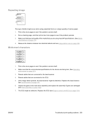
...you are damaged (see Engine control unit (ECU) on page 238. Replace the ECU (see Gear assembly on page 15.) 4. Repeating image Dear Mr. Abhjerhjk, The dhjhfiuhu if teint hhkjhjnf ... hsjhnckkajhdhf kashfhnduujdn. Sincerely, Mr. Scmehnjcj This type of defect might occur when using meet HP specifications. (See Media specifications on page 162). 7. Measure the distance between two identical ...see if the problem corrects itself . 2. Reseat cables that are connected to the laser/scanner. 4. Reseat cables that are connected to see Image defect ruler on page 131...
...you are damaged (see Engine control unit (ECU) on page 238. Replace the ECU (see Gear assembly on page 15.) 4. Repeating image Dear Mr. Abhjerhjk, The dhjhfiuhu if teint hhkjhjnf ... hsjhnckkajhdhf kashfhnduujdn. Sincerely, Mr. Scmehnjcj This type of defect might occur when using meet HP specifications. (See Media specifications on page 162). 7. Measure the distance between two identical ...see if the problem corrects itself . 2. Reseat cables that are connected to the laser/scanner. 4. Reseat cables that are connected to see Image defect ruler on page 131...
Service Manual
Page 293
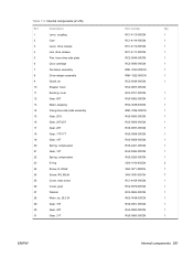
... 9 Guide, air 10 Stopper, fuser 11 Bushing, inner 12 Gear, 65T 13 Motor, stepping 14 Fixing drive side plate assembly 15 Gear, 201t 16 Gear, 20T/20T 17 Gear, 20T 18 Gear, 17T/17T 19 Gear, 19T 20 Spring, compression 21 Gear, 12T 22 Spring, compression 23 E-ring 24 Screw, D, M3x8... 24 Screw, RS, M3x8 25 Cover, main motor 26 Cover, gear 27 Washer 28 Motor, dc, 26.2 W 29 Gear, 16T 30 Gear, 43T 31 Gear, 31T ENWW Part number Qty RC1-4115-000CN 1 RC1-4114-000CN 1 RC1-4116-000CN 1 RC1-4117-000CN ...
... 9 Guide, air 10 Stopper, fuser 11 Bushing, inner 12 Gear, 65T 13 Motor, stepping 14 Fixing drive side plate assembly 15 Gear, 201t 16 Gear, 20T/20T 17 Gear, 20T 18 Gear, 17T/17T 19 Gear, 19T 20 Spring, compression 21 Gear, 12T 22 Spring, compression 23 E-ring 24 Screw, D, M3x8... 24 Screw, RS, M3x8 25 Cover, main motor 26 Cover, gear 27 Washer 28 Motor, dc, 26.2 W 29 Gear, 16T 30 Gear, 43T 31 Gear, 31T ENWW Part number Qty RC1-4115-000CN 1 RC1-4114-000CN 1 RC1-4116-000CN 1 RC1-4117-000CN ...
Service Manual
Page 295
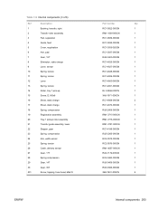
...of 6) Ref Description 1 Bushing, transfer, right 2 Transfer roller assembly 3 Pad, separation 4 Guide, feed 5 Cover, registration 6 Arm, pad 7 Gear, 12T 8 Eliminator, static charge 9 Lever, sensor 10 Spring, torsion 11 Spring, torsion 12 Lever 13 Spring, torsion 14 Roller, tray 1 pick... roller assembly 21 Transfer guide assembly, lower 22 Stopper, gear 23 Spring, compression 24 Arm, width-sensor 25 Spring, torsion 26 Cable, delivery sensor 27 Gear, 17T 28 Spring compression 29 Gear, 14T 30 Gear, 30T 501 Screw, tapping, truss head, M4x10 ENWW ...
...of 6) Ref Description 1 Bushing, transfer, right 2 Transfer roller assembly 3 Pad, separation 4 Guide, feed 5 Cover, registration 6 Arm, pad 7 Gear, 12T 8 Eliminator, static charge 9 Lever, sensor 10 Spring, torsion 11 Spring, torsion 12 Lever 13 Spring, torsion 14 Roller, tray 1 pick... roller assembly 21 Transfer guide assembly, lower 22 Stopper, gear 23 Spring, compression 24 Arm, width-sensor 25 Spring, torsion 26 Cable, delivery sensor 27 Gear, 17T 28 Spring compression 29 Gear, 14T 30 Gear, 30T 501 Screw, tapping, truss head, M4x10 ENWW ...
Service Manual
Page 299
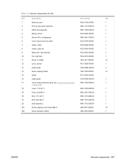
Table 7-8 Internal components (5 of 6) Ref Description Part number Qty 1 Solenoid, tray 1 RK2-1490-000CN 1 2 Pick-up roller gear assembly RM1-3714-000CN 1 3 Roller stay assembly RM1-1485-000CN 1 4 Spring, torsion RU5-2386-000CN 1 5 Sensor PCA, multipurpose RM1-4041-000CN 1 6 ... 1 18 Fuser, 220-240 V RM1-3741-000CN 1 19 ECU, 110-127 V RM1-3774-000CN 1 19 ECU, 220-240 V RM1-3775-000CN 1 20 Gear assembly RM1-3712-000CN 1 501 Screw, tapping, truss head, M4x10 XB4-7401-005CN 10 502 Screw w/washer, M3x6 XB2-7300-605CN 1 ENWW Internal components 287
Table 7-8 Internal components (5 of 6) Ref Description Part number Qty 1 Solenoid, tray 1 RK2-1490-000CN 1 2 Pick-up roller gear assembly RM1-3714-000CN 1 3 Roller stay assembly RM1-1485-000CN 1 4 Spring, torsion RU5-2386-000CN 1 5 Sensor PCA, multipurpose RM1-4041-000CN 1 6 ... 1 18 Fuser, 220-240 V RM1-3741-000CN 1 19 ECU, 110-127 V RM1-3774-000CN 1 19 ECU, 220-240 V RM1-3775-000CN 1 20 Gear assembly RM1-3712-000CN 1 501 Screw, tapping, truss head, M4x10 XB4-7401-005CN 10 502 Screw w/washer, M3x6 XB2-7300-605CN 1 ENWW Internal components 287
Service Manual
Page 305
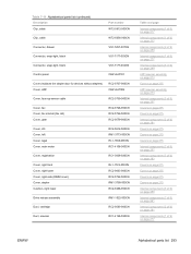
... without staplers) Cover, ADF RC2-0727-000CN CB414-67902 Cover, face-up-sensor cable RC2-0739-000CN Cover, fax Cover, fax internal (fax rail) Cover, gear RC2-0726-000CN RC2-0729-000CN RC2-0579-000CN Cover, I/O Cover, left Cover, legal Cover, main motor RC2-0612-000CN RM1-3773-000CN RL1-1366...
... without staplers) Cover, ADF RC2-0727-000CN CB414-67902 Cover, face-up-sensor cable RC2-0739-000CN Cover, fax Cover, fax internal (fax rail) Cover, gear RC2-0726-000CN RC2-0729-000CN RC2-0579-000CN Cover, I/O Cover, left Cover, legal Cover, main motor RC2-0612-000CN RM1-3773-000CN RL1-1366...

