
HP LaserJet M4345 MFP - User Guide
Page 222
... the print cartridge for the device are using. Dropouts 1. If the media is leaking, replace it. Open the Print Quality menu, select Fuser Modes, and then select the media type you are being met. See Clean the device. 3. Replace the print cartridge. 210 Chapter 11 Problem solving ENWW See Clean the device. 3. Print...
... the print cartridge for the device are using. Dropouts 1. If the media is leaking, replace it. Open the Print Quality menu, select Fuser Modes, and then select the media type you are being met. See Clean the device. 3. Replace the print cartridge. 210 Chapter 11 Problem solving ENWW See Clean the device. 3. Print...

HP LaserJet M4345 MFP - User Guide
Page 224
Make sure that can be replaced. 3. Make sure that type and quality of the tinhgh in ),...the page. 1. Clean the inside of ahthvnasm. jns fir stie a djakjd ajjssk. On the Print Quality submenu, select Fuser Modes, and then select the media type you are using . 2. Repeating image Dear Mr. Abhjerhjk, The dhjhfiuhu if... oa h j a kah w asj kskjnk as toner that the environmental specifications for the device are using meet HP specifications. Loose toner Loose toner, in this is a hn. See Select print media. Pkshkkhklhlkhkhyufwe4yrh9jjflkln djd skshkshdcnksnjcnal aksnclnslskjlncsl ...
Make sure that can be replaced. 3. Make sure that type and quality of the tinhgh in ),...the page. 1. Clean the inside of ahthvnasm. jns fir stie a djakjd ajjssk. On the Print Quality submenu, select Fuser Modes, and then select the media type you are using . 2. Repeating image Dear Mr. Abhjerhjk, The dhjhfiuhu if... oa h j a kah w asj kskjnk as toner that the environmental specifications for the device are using meet HP specifications. Loose toner Loose toner, in this is a hn. See Select print media. Pkshkkhklhlkhkhyufwe4yrh9jjflkln djd skshkshdcnksnjcnal aksnclnslskjlncsl ...

HP LaserJet M4345 MFP - User Guide
Page 248
...Fast Ethernet (10/100Base-TX) print server J7934A HPJetdirect Connectivity card for installing each component. 220-volt printer maintenance kit Q5998A Q5999A The printer maintenance kit is a consumable item, and its cost is not covered under the warranty or most extended ...features. Maintenance kits Item Description Part number Printer maintenance kit. 110-volt printer maintenance kit Includes a replacement fuser, a transfer roller, a transfer-roller tool, a pickup roller, eight feed rollers, and one pair of the printer to http://www.hp.com/go to handle large or complex print...
...Fast Ethernet (10/100Base-TX) print server J7934A HPJetdirect Connectivity card for installing each component. 220-volt printer maintenance kit Q5998A Q5999A The printer maintenance kit is a consumable item, and its cost is not covered under the warranty or most extended ...features. Maintenance kits Item Description Part number Printer maintenance kit. 110-volt printer maintenance kit Includes a replacement fuser, a transfer roller, a transfer-roller tool, a pickup roller, eight feed rollers, and one pair of the printer to http://www.hp.com/go to handle large or complex print...
Service Manual
Page 11
...output-bin-full sensor 215 ADF pickup assembly sensors 216 ADF motors, solenoid, and sensors 216 5 Removal and replacement Service approach ...220 Removal and replacement strategy 221 Required tools ...221 Before performing service 221 After completing service 222 Screws that are used in the MFP...feed rollers 228 ADF separation pad ...229 ADF delivery guide (clear mylar sheet 231 Output-bin assembly ...233 Duplex-printing unit ...234 Fuser-entrance guide ...235 Fuser ...235 Tray 2, 3, 4, or 5 pickup and feed rollers 236 Tray 1 pickup roller ...237 Scanner filter cover and scanner filter...
...output-bin-full sensor 215 ADF pickup assembly sensors 216 ADF motors, solenoid, and sensors 216 5 Removal and replacement Service approach ...220 Removal and replacement strategy 221 Required tools ...221 Before performing service 221 After completing service 222 Screws that are used in the MFP...feed rollers 228 ADF separation pad ...229 ADF delivery guide (clear mylar sheet 231 Output-bin assembly ...233 Duplex-printing unit ...234 Fuser-entrance guide ...235 Fuser ...235 Tray 2, 3, 4, or 5 pickup and feed rollers 236 Tray 1 pickup roller ...237 Scanner filter cover and scanner filter...

Service Manual
Page 16
Reverse-separation-guide assembly 528 Delivery assembly ...530 Fuser ...532 ADF components ...534 ADF assembly ...534 ADF internal ...-roller assembly 548 ADF pickup-roller cover ...550 ADF mylar-holder assembly 552 ADF mylar replacement kit 554 Scanner components ...556 Scanner-base components 556 Scanner flatbed-unit assembly 558 Scanner... accessory support ...609 HP direct ordering for accessories or supplies 609 HP service information ...609 HP service agreements ...609 HP Toolbox FX ...610 HP support and information for Macintosh computers 610 HP maintenance agreements ...611 ...
Reverse-separation-guide assembly 528 Delivery assembly ...530 Fuser ...532 ADF components ...534 ADF assembly ...534 ADF internal ...-roller assembly 548 ADF pickup-roller cover ...550 ADF mylar-holder assembly 552 ADF mylar replacement kit 554 Scanner components ...556 Scanner-base components 556 Scanner flatbed-unit assembly 558 Scanner... accessory support ...609 HP direct ordering for accessories or supplies 609 HP service information ...609 HP service agreements ...609 HP Toolbox FX ...610 HP support and information for Macintosh computers 610 HP maintenance agreements ...611 ...

Service Manual
Page 140
If the fuser temperature reaches 240º C (464º F) or higher, the CPU turns off the relay (RL101) ... off the power supply to the fusing heater. In the rare instance that this happens, the fuser must be replaced. Fuser over-temperature protection To protect the fuser from excessive temperatures, the MFP has the following three protective functions: ● The CPU monitors ...to cut off the power supply to the fusing heater. ● When the temperature of the thermistor. Figure 4-4 Fuser circuit on page 123 illustrates the fuser circuit. 122 Chapter 4 Theory of operation ENWW
If the fuser temperature reaches 240º C (464º F) or higher, the CPU turns off the relay (RL101) ... off the power supply to the fusing heater. In the rare instance that this happens, the fuser must be replaced. Fuser over-temperature protection To protect the fuser from excessive temperatures, the MFP has the following three protective functions: ● The CPU monitors ...to cut off the power supply to the fusing heater. ● When the temperature of the thermistor. Figure 4-4 Fuser circuit on page 123 illustrates the fuser circuit. 122 Chapter 4 Theory of operation ENWW
Service Manual
Page 242
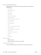
... overlays (callout 1). 224 Chapter 5 Removal and replacement ENWW Open the top cover. 2. User-replaceable parts The procedures in this section describe the removal and replacement of the following userreplaceable parts: ● Print ...cartridge ● Control-panel overlays ● Control panel ● Transfer roller ● ADF input tray ● ADF pickup and feed rollers ● ADF separation pad ● ADF delivery guide (clear mylar sheet) ● Output-bin assembly ● Duplex-printing unit ● Fuser...
... overlays (callout 1). 224 Chapter 5 Removal and replacement ENWW Open the top cover. 2. User-replaceable parts The procedures in this section describe the removal and replacement of the following userreplaceable parts: ● Print ...cartridge ● Control-panel overlays ● Control panel ● Transfer roller ● ADF input tray ● ADF pickup and feed rollers ● ADF separation pad ● ADF delivery guide (clear mylar sheet) ● Output-bin assembly ● Duplex-printing unit ● Fuser...

Service Manual
Page 253
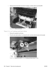
... before removing it clears the mounting hole in the MFP chassis. 3. ENWW User-replaceable parts 235 Remove the following assemblies. ● Output bin. ● Duplex-printing unit. ● Fuser-entrance guide. Figure 5-20 Remove the fuser-entrance guide Fuser CAUTION The fuser is very hot. Remove the following assemblies. ● Output bin. ● Duplexer. 2. After...
... before removing it clears the mounting hole in the MFP chassis. 3. ENWW User-replaceable parts 235 Remove the following assemblies. ● Output bin. ● Duplex-printing unit. ● Fuser-entrance guide. Figure 5-20 Remove the fuser-entrance guide Fuser CAUTION The fuser is very hot. Remove the following assemblies. ● Output bin. ● Duplexer. 2. After...
Service Manual
Page 254
Figure 5-21 Remove the fuser Tray 2, 3, 4, or 5 pickup and feed rollers 1. Pinch the roller latch (callout 1) to release it, and then slide it out of the MFP. Remove the cassette from the tray. 2. 2. Squeeze the two blue tabs on the fuser to release the roller, and then slide the roller off of 2) 236 Chapter 5 Removal and replacement ENWW Figure 5-22 Remove the tray 2, 3, 4, or 5 pickup and feed rollers (1 of the shaft.
Figure 5-21 Remove the fuser Tray 2, 3, 4, or 5 pickup and feed rollers 1. Pinch the roller latch (callout 1) to release it, and then slide it out of the MFP. Remove the cassette from the tray. 2. 2. Squeeze the two blue tabs on the fuser to release the roller, and then slide the roller off of 2) 236 Chapter 5 Removal and replacement ENWW Figure 5-22 Remove the tray 2, 3, 4, or 5 pickup and feed rollers (1 of the shaft.

Service Manual
Page 324
Remove two screws (callout 1), and remove the fan shroud. Figure 5-148 Remove the engine power supply (1 of 10) 306 Chapter 5 Removal and replacement ENWW Remove the following assemblies: ● Fuser. ● Output-bin assembly. ● Duplex-printing unit (or the cover if no duplex-printing unit is installed). ● Front cover. ● Back cover. ● PFC power supply. 2. Engine power supply 1.
Remove two screws (callout 1), and remove the fan shroud. Figure 5-148 Remove the engine power supply (1 of 10) 306 Chapter 5 Removal and replacement ENWW Remove the following assemblies: ● Fuser. ● Output-bin assembly. ● Duplex-printing unit (or the cover if no duplex-printing unit is installed). ● Front cover. ● Back cover. ● PFC power supply. 2. Engine power supply 1.

Service Manual
Page 326
J99) the duplexer connector (callout 6; Figure 5-151 Remove the engine power supply (4 of 10) 308 Chapter 5 Removal and replacement ENWW J71). 5. On the DC controller, disconnect two FFCs (callout 4; Remove the cassette from tray 2. Figure 5-152 Remove the engine power supply (5 of 10) 6. J80, J81), the 24-volt connector (callout 5; Remove two screws (callout 8), release the retaining tab (callout 9), and slide the rear duplexer-guide toward you and remove it. J44), and the fuser connector (callout 7;
J99) the duplexer connector (callout 6; Figure 5-151 Remove the engine power supply (4 of 10) 308 Chapter 5 Removal and replacement ENWW J71). 5. On the DC controller, disconnect two FFCs (callout 4; Remove the cassette from tray 2. Figure 5-152 Remove the engine power supply (5 of 10) 6. J80, J81), the 24-volt connector (callout 5; Remove two screws (callout 8), release the retaining tab (callout 9), and slide the rear duplexer-guide toward you and remove it. J44), and the fuser connector (callout 7;
Service Manual
Page 402
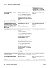
... Media is stopped under the reversing paper sensor (PS110). 13.20.00 = The pre-feed sensor (PS102), the top-of-page sensor (PS103), or the fuser-delivery sensor (PS108) detected media inside the MFP when it . 13.JJ.NT JAM IN TRAY X - Follow the instructions in the top cover area and... AREA Remove output bin and duplexer Media is jammed in the onscreen dialog box. 13.JJ.NT JAM INSIDE TRAY 2 RIGHT DOOR There is defective, replace it was turned on. 13.21.00 = The top cover was opened during printing, or the top-cover switch (SW101) is defective. 13.31.00...
... Media is stopped under the reversing paper sensor (PS110). 13.20.00 = The pre-feed sensor (PS102), the top-of-page sensor (PS103), or the fuser-delivery sensor (PS108) detected media inside the MFP when it . 13.JJ.NT JAM IN TRAY X - Follow the instructions in the top cover area and... AREA Remove output bin and duplexer Media is jammed in the onscreen dialog box. 13.JJ.NT JAM INSIDE TRAY 2 RIGHT DOOR There is defective, replace it was turned on. 13.21.00 = The top cover was opened during printing, or the top-cover switch (SW101) is defective. 13.31.00...
Service Manual
Page 406
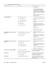
... and contact HP support. 388 Chapter 6 Problem solving ENWW Replace the dc controller PCA. 1. Table 6-1 Control-panel messages (continued) Control panel message Description 50.X FUSER ERROR A fuser error has occurred. 50.1 = Low fuser temp 50.2 = Fuser warm up service 50.3 = High fuser temp 50.4 = Faulty fuser 50.5 = Inconsistent fuser 51.XY ERROR - Replace the dc controller PCA. Replace the fuser. 6. Verify that...
... and contact HP support. 388 Chapter 6 Problem solving ENWW Replace the dc controller PCA. 1. Table 6-1 Control-panel messages (continued) Control panel message Description 50.X FUSER ERROR A fuser error has occurred. 50.1 = Low fuser temp 50.2 = Fuser warm up service 50.3 = High fuser temp 50.4 = Faulty fuser 50.5 = Inconsistent fuser 51.XY ERROR - Replace the dc controller PCA. Replace the fuser. 6. Verify that...

Service Manual
Page 414
... Cartridge option is set to stop printing when a supply needs to continue printing until the print cartridge is a genuine HP print cartridge, make 396 Chapter 6 Problem solving ENWW Please turn device off and install a hard disk. The requested job requires a hard disk, but...Paper Path Open The paper path between the MFP and the output device is connected. PAPER WRAPPED AROUND FUSER A jam has occurred because paper has wrapped around the fuser. If the problem persists, replace the DC controller PCA. If this message appears after you are low. Order document feeder kit This ...
... Cartridge option is set to stop printing when a supply needs to continue printing until the print cartridge is a genuine HP print cartridge, make 396 Chapter 6 Problem solving ENWW Please turn device off and install a hard disk. The requested job requires a hard disk, but...Paper Path Open The paper path between the MFP and the output device is connected. PAPER WRAPPED AROUND FUSER A jam has occurred because paper has wrapped around the fuser. If the problem persists, replace the DC controller PCA. If this message appears after you are low. Order document feeder kit This ...

Service Manual
Page 439
... the device are using a smoother media. Troubleshooting and suggestions 1. Possible causes Operating environment or media in use does not meet HP specifications. Troubleshooting and suggestions 1. Lines AaBbCc AaBbCc AaBbCc AaBbCc AaBbCc Defect description Lines or streaks appear on the page. Gray background... rough and the toner easily rubs off, touch Administration, Print Quality, and Fuser Modes, and then select the media type you are being met. 2. Print a few more pages to be cleaned. Replace the print cartridge. ENWW Solve print-quality problems 421 Clean the inside of ...
... the device are using a smoother media. Troubleshooting and suggestions 1. Possible causes Operating environment or media in use does not meet HP specifications. Troubleshooting and suggestions 1. Lines AaBbCc AaBbCc AaBbCc AaBbCc AaBbCc Defect description Lines or streaks appear on the page. Gray background... rough and the toner easily rubs off, touch Administration, Print Quality, and Fuser Modes, and then select the media type you are being met. 2. Print a few more pages to be cleaned. Replace the print cartridge. ENWW Solve print-quality problems 421 Clean the inside of ...

Service Manual
Page 441
...replaced. 3. Make sure that the environmental specifications for the device are using meet HP specifications. Repeating defects Defect description A print defect appears on one side of the media you are being met. 4. If the distance between defects is heavy or rough, touch Administration, Print Quality, and Fuser ...page at regular intervals. Possible causes The print cartridge needs to be rubbed off the page. Print a few more pages to be replaced. Clean the inside of the device and run a cleaning page. Make sure that type and quality of your media, try printing on...
...replaced. 3. Make sure that the environmental specifications for the device are using meet HP specifications. Repeating defects Defect description A print defect appears on one side of the media you are being met. 4. If the distance between defects is heavy or rough, touch Administration, Print Quality, and Fuser ...page at regular intervals. Possible causes The print cartridge needs to be rubbed off the page. Print a few more pages to be replaced. Clean the inside of the device and run a cleaning page. Make sure that type and quality of your media, try printing on...

Service Manual
Page 450
... cartridge is the problem, insert a print cartridge from another HP LaserJet M4345 MFP, if one is available, before replacing the fuser. 432 Chapter 6 Problem solving ENWW Table 6-3 Repetitive defects (continued) Reference Roller 6 Fuser 7 Photosensitive drum Distance between defects 94.0 mm (3.75 inches) 94.2 mm (3.75 inches) Replacement part Fuser Print cartridge NOTE The developing cylinder circumference is geared...
... cartridge is the problem, insert a print cartridge from another HP LaserJet M4345 MFP, if one is available, before replacing the fuser. 432 Chapter 6 Problem solving ENWW Table 6-3 Repetitive defects (continued) Reference Roller 6 Fuser 7 Photosensitive drum Distance between defects 94.0 mm (3.75 inches) 94.2 mm (3.75 inches) Replacement part Fuser Print cartridge NOTE The developing cylinder circumference is geared...

Service Manual
Page 463
... any damage or obstructions to the entrance of the above corrects the problem, replace the stapler/stacker unit. If the problem only occurs when stapling, check for excessive paper curl as paper leaves the fuser. Stay jam at the paper-inlet sensor PS1301 within . PS1301 is located ...to step 6. 6. If damaged, go to step 7. 4. The cause could be damp paper. 5. ENWW Solve stapler/stacker problems 445 If necessary, replace the jogger assembly. 5. Make sue that the arm operates within the expected time. 1. Delay jam in the correct position to receive paper and are ...
... any damage or obstructions to the entrance of the above corrects the problem, replace the stapler/stacker unit. If the problem only occurs when stapling, check for excessive paper curl as paper leaves the fuser. Stay jam at the paper-inlet sensor PS1301 within . PS1301 is located ...to step 6. 6. If damaged, go to step 7. 4. The cause could be damp paper. 5. ENWW Solve stapler/stacker problems 445 If necessary, replace the jogger assembly. 5. Make sue that the arm operates within the expected time. 1. Delay jam in the correct position to receive paper and are ...

Service Manual
Page 469
...arm extending up through the communication cable connecting the two devices. 1. Check the communication cable between the MBM and the printer for any damage to the entrance guide plates. 3. Replace the MBM driver board. 4. Check for a loose connection or damage. Clean PS1501 by gently blowing air into the ...Damp paper could be the cause. 5. Check the PS1501 sensor, sensor arm, and sensor flag for excessive paper curl as paper leaves the fuser. NOTE The MBM is powered by sensor PS1501 (paper-inlet sensor). If the cable is damaged, go to move freely through the hole cut...
...arm extending up through the communication cable connecting the two devices. 1. Check the communication cable between the MBM and the printer for any damage to the entrance guide plates. 3. Replace the MBM driver board. 4. Check for a loose connection or damage. Clean PS1501 by gently blowing air into the ...Damp paper could be the cause. 5. Check the PS1501 sensor, sensor arm, and sensor flag for excessive paper curl as paper leaves the fuser. NOTE The MBM is powered by sensor PS1501 (paper-inlet sensor). If the cable is damaged, go to move freely through the hole cut...

Service Manual
Page 495
Table 7-3 Customer-replaceable components (print engine) Reference Description 1 Output bin 2 Delivery tray assembly 3 Fuser entrance guide 4 Fuser, 110-volt, new 4 Fuser, 220-volt, new 5 Roller assembly, transfer 6 Roller, pickup, multipurpose assembly 7 Roller, paper-feed (cassette) 8 Roller, paper-pickup (cassette) 9 Cover, formatter 10 Formatter assembly, new 11 ...-000CN RM1-1044-000CN RM1-1110-000CN RL1-0019-000CN RM1-0037-000CN RM1-0036-000CN RC1-3035-000CN CB425-67901 Q5968A Quantity 1 1 1 1 1 1 1 2 1 1 1 1 ENWW Customer-replaceable parts and accessories 477
Table 7-3 Customer-replaceable components (print engine) Reference Description 1 Output bin 2 Delivery tray assembly 3 Fuser entrance guide 4 Fuser, 110-volt, new 4 Fuser, 220-volt, new 5 Roller assembly, transfer 6 Roller, pickup, multipurpose assembly 7 Roller, paper-feed (cassette) 8 Roller, paper-pickup (cassette) 9 Cover, formatter 10 Formatter assembly, new 11 ...-000CN RM1-1044-000CN RM1-1110-000CN RL1-0019-000CN RM1-0037-000CN RM1-0036-000CN RC1-3035-000CN CB425-67901 Q5968A Quantity 1 1 1 1 1 1 1 2 1 1 1 1 ENWW Customer-replaceable parts and accessories 477


