Service Manual
Page 344
... cover 141 Left side cover 143 Front right side cover 144 Rear cover/rear output bin 145 Tray 1 146 Removing internal assemblies 149 Fuser 149 Firmware DIMM 150 Formatter assembly 151 Output delivery assembly 152 Laser/scanner 154 Cartridge memory 155 Fan 156 Main motor 158 Transfer roller 159 Tray 1 pickup roller 160 Tray...
... cover 141 Left side cover 143 Front right side cover 144 Rear cover/rear output bin 145 Tray 1 146 Removing internal assemblies 149 Fuser 149 Firmware DIMM 150 Formatter assembly 151 Output delivery assembly 152 Laser/scanner 154 Cartridge memory 155 Fan 156 Main motor 158 Transfer roller 159 Tray 1 pickup roller 160 Tray...

Service Manual
Page 347
... 107. Figure 56. Figure 74. Unlocking the fuser assembly 149 Installing a firmware DIMM 150 Removing the formatter assembly 151 Removing the output delivery assembly 152 Left end of output delivery assembly (brass arm 152 Right end of output delivery assembly (white tab 153 Removing the laser/scanner 154... 190 Sample event log 191 Sample menu map (1 of 2 223 Sample menu map (2 of 2 223 Sample configuration page (HP LaserJet 4100 series printer 227 Repetitive print defect ruler 243 Components of the paper pickup and feed system 246 Components of the optional paper feeder...
... 107. Figure 56. Figure 74. Unlocking the fuser assembly 149 Installing a firmware DIMM 150 Removing the formatter assembly 151 Removing the output delivery assembly 152 Left end of output delivery assembly (brass arm 152 Right end of output delivery assembly (white tab 153 Removing the laser/scanner 154... 190 Sample event log 191 Sample menu map (1 of 2 223 Sample menu map (2 of 2 223 Sample configuration page (HP LaserJet 4100 series printer 227 Repetitive print defect ruler 243 Components of the paper pickup and feed system 246 Components of the optional paper feeder...

Service Manual
Page 348
... components (2 of 4 282 Internal components (3 of 4 284 Internal components (4 of 4 286 Engine controller board assembly 288 Delivery drive assembly 289 Printer drive assembly 290 Tray 2 paper pickup guide assembly 291 Tray 1 pickup assembly 292 Paper feed guide assembly 294 Delivery assembly 295 Fuser assembly (1 of 2 296 Fuser assembly (2 of 2 297 Internal components of optional 500-sheet feeder 298 Paper pickup guide...
... components (2 of 4 282 Internal components (3 of 4 284 Internal components (4 of 4 286 Engine controller board assembly 288 Delivery drive assembly 289 Printer drive assembly 290 Tray 2 paper pickup guide assembly 291 Tray 1 pickup assembly 292 Paper feed guide assembly 294 Delivery assembly 295 Fuser assembly (1 of 2 296 Fuser assembly (2 of 2 297 Internal components of optional 500-sheet feeder 298 Paper pickup guide...

Service Manual
Page 351
... Internal components (1 of 4 281 Internal components (2 of 4 283 Internal components (3 of 4 285 Internal components (4 of 4 287 Engine controller board assembly 288 Delivery drive assembly 289 Printer drive assembly 290 Paper pickup guide assembly 291 Tray 1 pickup assembly 293 Paper feed assembly 294 Delivery assembly 295 Fuser assembly 296 Internal components of optional 500-sheet feeder 299 Paper pickup guide...
... Internal components (1 of 4 281 Internal components (2 of 4 283 Internal components (3 of 4 285 Internal components (4 of 4 287 Engine controller board assembly 288 Delivery drive assembly 289 Printer drive assembly 290 Paper pickup guide assembly 291 Tray 1 pickup assembly 293 Paper feed assembly 294 Delivery assembly 295 Fuser assembly 296 Internal components of optional 500-sheet feeder 299 Paper pickup guide...
Service Manual
Page 372
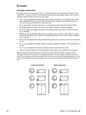
... going through the HP LaserJet printer without problems. However, some envelope constructions (as shown in the figure below) will not feed reliably. Avoid using envelopes with a sharp, well-creased fold that rely on envelopes. Do not use envelopes that the adhesive labels used on envelopes will feed through the printer's fuser assembly. ! Woven or...
... going through the HP LaserJet printer without problems. However, some envelope constructions (as shown in the figure below) will not feed reliably. Avoid using envelopes with a sharp, well-creased fold that rely on envelopes. Do not use envelopes that the adhesive labels used on envelopes will feed through the printer's fuser assembly. ! Woven or...

Service Manual
Page 404
...). Explanation Press SELECT to print a cleaning page (for the printer to select. Note It might take approximately two minutes for cleaning excess toner from the fuser assembly). In order for the cleaning page to select. Follow the instructions on the cleaning page. Print quality menu (continued) Item Values CREATE CLEANING PAGE No...
...). Explanation Press SELECT to print a cleaning page (for the printer to select. Note It might take approximately two minutes for cleaning excess toner from the fuser assembly). In order for the cleaning page to select. Follow the instructions on the cleaning page. Print quality menu (continued) Item Values CREATE CLEANING PAGE No...

Service Manual
Page 423
or A4-sized media from the fuser assembly, shiny black spots will appear on the page's black strip. To override a paper load message, press GO, and then answer the questions on the black ... (not bond or rough paper). When toner has been cleaned from a tray. Using the auto-cleaning page The auto-cleaning page feature helps keep the fuser rollers clean, which maintains excellent output quality. The settings can be changed or the feature can be used for the cleaning page to create and...
or A4-sized media from the fuser assembly, shiny black spots will appear on the page's black strip. To override a paper load message, press GO, and then answer the questions on the black ... (not bond or rough paper). When toner has been cleaned from a tray. Using the auto-cleaning page The auto-cleaning page feature helps keep the fuser rollers clean, which maintains excellent output quality. The settings can be changed or the feature can be used for the cleaning page to create and...

Service Manual
Page 426
... 1 separation pad RF5-3086-000CN 200,000 pages (for tray 1) 3 Tray 1 pickup assembly RG5-5084-000CN 200,000 pages (for tray 1) 4 Feed and separation rollers RF5-3114-000CN 200,000 pages (trays 2, 3, and 4) 5 Fuser 110 V 220 V RG5-5063-000CN RG5- 200,000 pages 5064-000CN 200,000 pages ...6 Transfer roller RG5-5295-000CN 200,000 pages 7 Cooling fan RH7-1442-000CN 25,000 hours 8 Duplexer exhaust fan RH7-1443-000CN 25,000 hours If an HP LaserJet 4100 series printer component is...
... 1 separation pad RF5-3086-000CN 200,000 pages (for tray 1) 3 Tray 1 pickup assembly RG5-5084-000CN 200,000 pages (for tray 1) 4 Feed and separation rollers RF5-3114-000CN 200,000 pages (trays 2, 3, and 4) 5 Fuser 110 V 220 V RG5-5063-000CN RG5- 200,000 pages 5064-000CN 200,000 pages ...6 Transfer roller RG5-5295-000CN 200,000 pages 7 Cooling fan RH7-1442-000CN 25,000 hours 8 Duplexer exhaust fan RH7-1443-000CN 25,000 hours If an HP LaserJet 4100 series printer component is...

Service Manual
Page 459
..., the printer starts the initial rotation phase. (This consists of main motor warm-up, scanner motor warm-up, high-voltage control sequence and fuser warm-up.) When the initial rotation phase ends, the tray 1 pickup solenoid (SL102) is corrected. When the engine controller board receives the ...tray 1 The presence of media in tray 1 is delivered to six times and a jam will be detected. The sheet then reaches the registration assembly, where its skew is activated. Printing from tray 1 just before it goes through the delivery unit; and is detected by the tray 1 paper ...
..., the printer starts the initial rotation phase. (This consists of main motor warm-up, scanner motor warm-up, high-voltage control sequence and fuser warm-up.) When the initial rotation phase ends, the tray 1 pickup solenoid (SL102) is corrected. When the engine controller board receives the ...tray 1 The presence of media in tray 1 is delivered to six times and a jam will be detected. The sheet then reaches the registration assembly, where its skew is activated. Printing from tray 1 just before it goes through the delivery unit; and is detected by the tray 1 paper ...

Service Manual
Page 472
... cover 141 Left side cover 143 Front right side cover 144 Rear cover/rear output bin 145 Tray 1 146 Removing internal assemblies 149 Fuser 149 Firmware DIMM 150 Formatter assembly 151 Output delivery assembly 152 Laser/scanner 154 Cartridge memory 155 Fan 156 Main motor 158 Transfer roller 159 Tray 1 pickup roller 160 Tray...
... cover 141 Left side cover 143 Front right side cover 144 Rear cover/rear output bin 145 Tray 1 146 Removing internal assemblies 149 Fuser 149 Firmware DIMM 150 Formatter assembly 151 Output delivery assembly 152 Laser/scanner 154 Cartridge memory 155 Fan 156 Main motor 158 Transfer roller 159 Tray 1 pickup roller 160 Tray...

Service Manual
Page 488
...locked position. EN Chapter 6 Removing and replacing parts 149 Removing internal assemblies Fuser WARNING! CAUTION Hint Unlocking the fuser assembly 3 Rotate the two blue levers on the fuser assembly up to the fuser assembly, do not grasp the fuser by pulling from the bottom. 2 Remove the rear cover/rear ...bin (page 145). Figure 53. To prevent damage to the unlocked position. 4 Pull the fuser assembly straight out of the printer by the black plastic diverter. Make sure the fuser assembly is seated fully before removal. 1 If a duplexer is not installed, remove the tray ...
...locked position. EN Chapter 6 Removing and replacing parts 149 Removing internal assemblies Fuser WARNING! CAUTION Hint Unlocking the fuser assembly 3 Rotate the two blue levers on the fuser assembly up to the fuser assembly, do not grasp the fuser by pulling from the bottom. 2 Remove the rear cover/rear ...bin (page 145). Figure 53. To prevent damage to the unlocked position. 4 Pull the fuser assembly straight out of the printer by the black plastic diverter. Make sure the fuser assembly is seated fully before removal. 1 If a duplexer is not installed, remove the tray ...

Service Manual
Page 508
... Then, pull outward to release it from the white plastic cable guide. d Remove the left side cover (page 143). k Remove the registration assembly (page 165). Printer drive assembly (gear train) 12 Figure 76. c Remove the top cover (page 141). j Remove the right side toner cartridge guide (page 164). e... Remove the front right side cover (page 144). EN Chapter 6 Removing and replacing parts 169 Note Note Removing the printer drive assembly 1 To remove the printer drive assembly: a Remove the rear right side cover (page 138). g Remove the fuser assembly (page 149).
... Then, pull outward to release it from the white plastic cable guide. d Remove the left side cover (page 143). k Remove the registration assembly (page 165). Printer drive assembly (gear train) 12 Figure 76. c Remove the top cover (page 141). j Remove the right side toner cartridge guide (page 164). e... Remove the front right side cover (page 144). EN Chapter 6 Removing and replacing parts 169 Note Note Removing the printer drive assembly 1 To remove the printer drive assembly: a Remove the rear right side cover (page 138). g Remove the fuser assembly (page 149).

Service Manual
Page 509
...-pin connector (callout 2) shown. 4 Lift the delivery drive assembly upward, away from the printer. 170 Removing and replacing parts EN e Remove the fuser assembly (page 149). Removing the delivery drive assembly 1 To remove the delivery drive assembly: a Remove the rear right side cover (page 138). Delivery drive assembly 2 12 Figure 77. c Remove the top cover (page...
...-pin connector (callout 2) shown. 4 Lift the delivery drive assembly upward, away from the printer. 170 Removing and replacing parts EN e Remove the fuser assembly (page 149). Removing the delivery drive assembly 1 To remove the delivery drive assembly: a Remove the rear right side cover (page 138). Delivery drive assembly 2 12 Figure 77. c Remove the top cover (page...

Service Manual
Page 512
The engine controller board is on page 175. 1 Remove the fuser assembly (page 149). 2 Separate the engine from the paper-feed module (page 171). EN Chapter 6 Removing and replacing parts 173 Figure 80. Removing the engine controller ...
The engine controller board is on page 175. 1 Remove the fuser assembly (page 149). 2 Separate the engine from the paper-feed module (page 171). EN Chapter 6 Removing and replacing parts 173 Figure 80. Removing the engine controller ...

Service Manual
Page 515
... controller board grounding spring might interfere with removal. 176 Removing and replacing parts EN i Remove the tray 1 pickup assembly (page 161). o Remove the engine controller board (page 173). 2 Remove the plastic main gear cable guide by...assembly. h Remove tray 1 (page 146). c Remove the top cover (page 141). b Remove the control panel (page 139). d Remove the left side cover (page 143). j Remove the right side toner cartridge guide (page 164). l Remove the formatter assembly (page 151). m Remove the printer drive assembly (page 169). g Remove the fuser assembly...
... controller board grounding spring might interfere with removal. 176 Removing and replacing parts EN i Remove the tray 1 pickup assembly (page 161). o Remove the engine controller board (page 173). 2 Remove the plastic main gear cable guide by...assembly. h Remove tray 1 (page 146). c Remove the top cover (page 141). b Remove the control panel (page 139). d Remove the left side cover (page 143). j Remove the right side toner cartridge guide (page 164). l Remove the formatter assembly (page 151). m Remove the printer drive assembly (page 169). g Remove the fuser assembly...

Service Manual
Page 580
... the guide. Table 42. If the problem continues, replace the toner cartridge. teeth. Redistribute the toner in the laser path. 1. Replace the laser/scanner assembly. Replace the fuser assembly. Vertical dots Contaminated static eliminator Clean the static eliminator. Replace the toner cartridge. If the problem remains after cleaning, or parts are damaged or...
... the guide. Table 42. If the problem continues, replace the toner cartridge. teeth. Redistribute the toner in the laser path. 1. Replace the laser/scanner assembly. Replace the fuser assembly. Vertical dots Contaminated static eliminator Clean the static eliminator. Replace the toner cartridge. If the problem remains after cleaning, or parts are damaged or...
Service Manual
Page 591
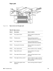
... Top output bin full sensor Sensor located on top output bin assembly PS105 Tray 1 paper sensor Sensor located on tray 1 assembly PS106 Paper width sensor Sensor located on the output assembly PS107 Fuser paper-delivery sensor 2 Sensor and flag located on fuser assembly PS108 Fuser paper-delivery sensor 1 Sensor located on engine controller flags on engine controller...
... Top output bin full sensor Sensor located on top output bin assembly PS105 Tray 1 paper sensor Sensor located on tray 1 assembly PS106 Paper width sensor Sensor located on the output assembly PS107 Fuser paper-delivery sensor 2 Sensor and flag located on fuser assembly PS108 Fuser paper-delivery sensor 1 Sensor located on engine controller flags on engine controller...

Service Manual
Page 613
Assembly location diagram (1 of 2) 1 Tray 1 pickup assembly 2 Tray 1 assembly 3 Fuser assembly 4 Paper delivery assembly 5 Top cover assembly 274 Parts and diagrams EN Illustrations and parts lists 4 5 1 3 2 Figure 118.
Assembly location diagram (1 of 2) 1 Tray 1 pickup assembly 2 Tray 1 assembly 3 Fuser assembly 4 Paper delivery assembly 5 Top cover assembly 274 Parts and diagrams EN Illustrations and parts lists 4 5 1 3 2 Figure 118.

Service Manual
Page 635
Exchange no . Fuser assembly (1 of 2) Table 69. Quantity Description RG5-5063-000CN C8049-69001 RG5-5064-000CN C8049-69002 1 Fuser (110 V) 1 Fuser (220 V) 1 RB2-4919-000CN 1 Roller, pressure 2 RG5-5068-000CN RG5-5069-000CN 1 Fuser film assembly (110 V) 1 Fuser film assembly (220 V) 296 Parts and diagrams EN Fuser assembly Item no . Part no. 2 1 Figure 133.
Exchange no . Fuser assembly (1 of 2) Table 69. Quantity Description RG5-5063-000CN C8049-69001 RG5-5064-000CN C8049-69002 1 Fuser (110 V) 1 Fuser (220 V) 1 RB2-4919-000CN 1 Roller, pressure 2 RG5-5068-000CN RG5-5069-000CN 1 Fuser film assembly (110 V) 1 Fuser film assembly (220 V) 296 Parts and diagrams EN Fuser assembly Item no . Part no. 2 1 Figure 133.

Service Manual
Page 636
Figure 134. Fuser assembly (2 of 2) EN Chapter 8 Parts and diagrams 297
Figure 134. Fuser assembly (2 of 2) EN Chapter 8 Parts and diagrams 297


