HP PCL/PJL reference - Printer Job Language Technical Reference Addendum
Page 142
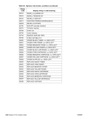
...or code meaning INSTALL CLEANING KIT INSTALL TRANFER KIT INSTALL FUSER KIT PERFORM PRINTER MAINTENANCE INSTALL SUPPLIES NON-HP Cartridge Installed T2 Roller missing Croller out Croller missing REMOVE SEALING TAPE E-label cartridge error ORDER BLACK TONER DAYS LEFT ORDER ... MAGENTA CARTRIDGE DAYS LEFT ORDER YELLOW CARTRIDGE DAYS LEFT ORDER SUPPLIES DAYS LEFT REPLACE BLACK TONER REPLACE CYAN TONER REPLACE MAGENTA TONER REPLACE YELLOW TONER REPLACE BLACK CARTRIDGE REPLACE CYAN CARTRIDGE REPLACE MAGENTA CARTRIDGE REPLACE YELLOW CARTRIDGE REPLACE SUPPLIES 140 Chapter 4 PJL status codes ENWW
...or code meaning INSTALL CLEANING KIT INSTALL TRANFER KIT INSTALL FUSER KIT PERFORM PRINTER MAINTENANCE INSTALL SUPPLIES NON-HP Cartridge Installed T2 Roller missing Croller out Croller missing REMOVE SEALING TAPE E-label cartridge error ORDER BLACK TONER DAYS LEFT ORDER ... MAGENTA CARTRIDGE DAYS LEFT ORDER YELLOW CARTRIDGE DAYS LEFT ORDER SUPPLIES DAYS LEFT REPLACE BLACK TONER REPLACE CYAN TONER REPLACE MAGENTA TONER REPLACE YELLOW TONER REPLACE BLACK CARTRIDGE REPLACE CYAN CARTRIDGE REPLACE MAGENTA CARTRIDGE REPLACE YELLOW CARTRIDGE REPLACE SUPPLIES 140 Chapter 4 PJL status codes ENWW
Service Manual
Page 6
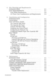
... EXPECTANCY . 4-2 VERIFYING PRINTER MAINTENANCE 4-3 USER MAINTENANCE 4-4 Fusing Assembly 4-5 Transfer Roller 4-7 Transfer Roller Replacement 4-8 Contents-2 2. Site Planning and Requirements INTRODUCTION 2-1 SITE REQUIREMENTS 2-1 Print Media Specifications 2-2 AC Power Line Considerations and Requirements 2-4 3. Installation and Configuration INTRODUCTION 3-1 UNPACKING 3-2 THE CONTROL PANEL 3-3 The LaserJet HISi Panel 3-4 The LaserJet 4Si Panel 3-4 LaserJet 4Si Menu Map 3-5 Localizing the Control Panel 3-5 Configuring for...
... EXPECTANCY . 4-2 VERIFYING PRINTER MAINTENANCE 4-3 USER MAINTENANCE 4-4 Fusing Assembly 4-5 Transfer Roller 4-7 Transfer Roller Replacement 4-8 Contents-2 2. Site Planning and Requirements INTRODUCTION 2-1 SITE REQUIREMENTS 2-1 Print Media Specifications 2-2 AC Power Line Considerations and Requirements 2-4 3. Installation and Configuration INTRODUCTION 3-1 UNPACKING 3-2 THE CONTROL PANEL 3-3 The LaserJet HISi Panel 3-4 The LaserJet 4Si Panel 3-4 LaserJet 4Si Menu Map 3-5 Localizing the Control Panel 3-5 Configuring for...
Service Manual
Page 7
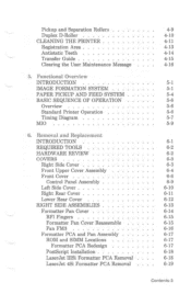
... AND FEED SYSTEM BASIC SEQUENCE OF OPERATION Overview Standard Printer Operation Timing Diagram MIO 6. Removal and Replacement INTRODUCTION REQUIRED TOOLS HARDWARE REVIEW COVERS Right Side Cover Front Upper Cover Assembly Front Cover Control Panel Assembly... Cover RFI Fingers Formatter Pan Cover Reassemble Fan FM3 Formatter PCA and Pan Assembly ROM and SIMM Locations Formatter PCA Redesign PostScript Installation LaserJet IIISi Formatter PCA Removal LaserJet 4Si Formatter PCA Removal 4-9 4-10 4-11 4-13 4-14 4-15 4-16 5-1 5-1 5-4 5-6 5-6 5-6 5-7 5-9 6-1 6-2 6-2 6-3 6-3 6-4 6-6 6-9 6-10 6-11 6-...
... AND FEED SYSTEM BASIC SEQUENCE OF OPERATION Overview Standard Printer Operation Timing Diagram MIO 6. Removal and Replacement INTRODUCTION REQUIRED TOOLS HARDWARE REVIEW COVERS Right Side Cover Front Upper Cover Assembly Front Cover Control Panel Assembly... Cover RFI Fingers Formatter Pan Cover Reassemble Fan FM3 Formatter PCA and Pan Assembly ROM and SIMM Locations Formatter PCA Redesign PostScript Installation LaserJet IIISi Formatter PCA Removal LaserJet 4Si Formatter PCA Removal 4-9 4-10 4-11 4-13 4-14 4-15 4-16 5-1 5-1 5-4 5-6 5-6 5-6 5-7 5-9 6-1 6-2 6-2 6-3 6-3 6-4 6-6 6-9 6-10 6-11 6-...
Service Manual
Page 64
Contents 4. Maintenance INTRODUCTION 4-1 User Maintenance Concept 4-1 PRINTER CONSUMABLES 4-1 TONER CARTRIDGE LIFE EXPECTANCY . 4-2 VERIFYING PRINTER MAINTENANCE 4-3 USER MAINTENANCE 4-4 Fusing Assembly 4-5 Transfer Roller 4-7 Transfer Roller Replacement 4-8 Pickup and Separation Rollers 4-9 Duplex D-Roller 4-10 CLEANING THE PRINTER 4-11 Registration Area 4-13 Antistatic Teeth 4-14 Transfer Guide 4-15 Clearing the User Maintenance Message 4-16
Contents 4. Maintenance INTRODUCTION 4-1 User Maintenance Concept 4-1 PRINTER CONSUMABLES 4-1 TONER CARTRIDGE LIFE EXPECTANCY . 4-2 VERIFYING PRINTER MAINTENANCE 4-3 USER MAINTENANCE 4-4 Fusing Assembly 4-5 Transfer Roller 4-7 Transfer Roller Replacement 4-8 Pickup and Separation Rollers 4-9 Duplex D-Roller 4-10 CLEANING THE PRINTER 4-11 Registration Area 4-13 Antistatic Teeth 4-14 Transfer Guide 4-15 Clearing the User Maintenance Message 4-16
Service Manual
Page 68
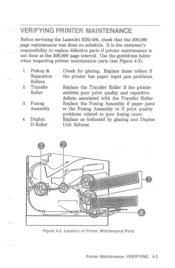
... when inspecting printer maintenance parts (see Figure 4-2). 1. Fusing Assembly 4. Duplex D-Roller Check for glazing. Location of Printer Maintenance Parts Printer Maintenance: VERIFYING 4-3 VERIFYING PRINTER MAINTENANCE Before servicing the LaserJet IIISi/4Si, check that the 200,000 page maintenance was done on schedule. Replace as indicated by glazing and Duplex Unit failures. -887--- - -O----Th...
... when inspecting printer maintenance parts (see Figure 4-2). 1. Fusing Assembly 4. Duplex D-Roller Check for glazing. Location of Printer Maintenance Parts Printer Maintenance: VERIFYING 4-3 VERIFYING PRINTER MAINTENANCE Before servicing the LaserJet IIISi/4Si, check that the 200,000 page maintenance was done on schedule. Replace as indicated by glazing and Duplex Unit failures. -887--- - -O----Th...
Service Manual
Page 69
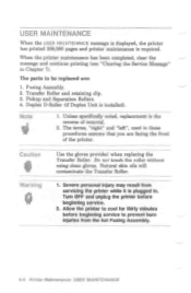
..." in these procedures assume that you are : 1. Pickup and Separation Rollers. 4. Natural skin oils will contaminate the Transfer Roller. 1. Duplex D-Roller (if Duplex Unit is the reverse of the printer. Unless specifically noted, replacement is installed). The terms, "right" and "left", used in Chapter... 7). Caution Warning Use the gloves provided when replacing the Transfer Roller. Fusing Assembly. 2. Transfer Roller and retaining clip. 3. The parts to prevent burn injuries from servicing the printer while it is required...
..." in these procedures assume that you are : 1. Pickup and Separation Rollers. 4. Natural skin oils will contaminate the Transfer Roller. 1. Duplex D-Roller (if Duplex Unit is the reverse of the printer. Unless specifically noted, replacement is installed). The terms, "right" and "left", used in Chapter... 7). Caution Warning Use the gloves provided when replacing the Transfer Roller. Fusing Assembly. 2. Transfer Roller and retaining clip. 3. The parts to prevent burn injuries from servicing the printer while it is required...
Service Manual
Page 72
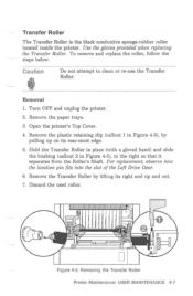
... the steps below. Remove the plastic retaining clip (callout 1 in Figure 4-5), to clean or re-use the Transfer Roller. Removing the Transfer Roller Printer Maintenance: USER MAINTENANCE 4-7 Open the printer's Top Cover. 4. For replacement, observe how the location pin fits into the slot of the Left Drive Gear. 6. Use the gloves provided when...
... the steps below. Remove the plastic retaining clip (callout 1 in Figure 4-5), to clean or re-use the Transfer Roller. Removing the Transfer Roller Printer Maintenance: USER MAINTENANCE 4-7 Open the printer's Top Cover. 4. For replacement, observe how the location pin fits into the slot of the Left Drive Gear. 6. Use the gloves provided when...
Service Manual
Page 73
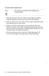
... the left end bushing, carefully seating the roll pin into the slot in place. If the roller is installed correctly, the clip will travel the full length of the Transfer Roller and right end bushing. 4. Close the printer and run a self test. Check that paper will ...snap over the shaft and guide, reducing lateral movement of the paper path without jamming. 4-8 Printer Maintenance: USER MAINTENANCE Replace the plastic retaining clip which holds the right end bushing in the bushing. 2. Transfer Roller Replacement Note IF Use the gloves provided when handling the Transfer...
... the left end bushing, carefully seating the roll pin into the slot in place. If the roller is installed correctly, the clip will travel the full length of the Transfer Roller and right end bushing. 4. Close the printer and run a self test. Check that paper will ...snap over the shaft and guide, reducing lateral movement of the paper path without jamming. 4-8 Printer Maintenance: USER MAINTENANCE Replace the plastic retaining clip which holds the right end bushing in the bushing. 2. Transfer Roller Replacement Note IF Use the gloves provided when handling the Transfer...

Service Manual
Page 74
... replacement parts for the Pickup and Separation Rollers are located inside the Paper Input Unit (see Figure 4-6). Remove both paper trays. 3. Discard the used rollers. 10 Figure 4-6. I. Remove each roller by pinching the light blue plastic retaining clip at the end of the roller and sliding it off its shaft (see Figure 4-6). Pickup and Separation Rollers...
... replacement parts for the Pickup and Separation Rollers are located inside the Paper Input Unit (see Figure 4-6). Remove both paper trays. 3. Discard the used rollers. 10 Figure 4-6. I. Remove each roller by pinching the light blue plastic retaining clip at the end of the roller and sliding it off its shaft (see Figure 4-6). Pickup and Separation Rollers...

Service Manual
Page 75
... Unit is keyed. With your right hand, pinch the clip on the end of the roller and slide it off to the right. Removing the Duplex D-Roller 4-10 Printer Maintenance: USER MAINTENANCE If not, duplex paper jams will need to pinch and remove the roller. Figure 4-7 shows how to be replaced during printer maintenance. 1.
... Unit is keyed. With your right hand, pinch the clip on the end of the roller and slide it off to the right. Removing the Duplex D-Roller 4-10 Printer Maintenance: USER MAINTENANCE If not, duplex paper jams will need to pinch and remove the roller. Figure 4-7 shows how to be replaced during printer maintenance. 1.

Service Manual
Page 76
Do not touch or clean the Transfer Roller without gloves when servicing the printer. Ammonia-based products cause permanent damage to avoid breathing toner ...Take care to the toner cartridge. Use a water dampened cloth to clean the printer. Note If toner gets on the Transfer Roller may result in severe personal injury. Never use ammonia-based cleaning solutions to clean the printer. Use the instructions in cold ... fi 1. Printer Maintenance: CLEANING THE PRINTER 4-11 CLEANING THE PRINTER Whenever the printer maintenance parts are replaced, the printer should also be cleaned.
Do not touch or clean the Transfer Roller without gloves when servicing the printer. Ammonia-based products cause permanent damage to avoid breathing toner ...Take care to the toner cartridge. Use a water dampened cloth to clean the printer. Note If toner gets on the Transfer Roller may result in severe personal injury. Never use ammonia-based cleaning solutions to clean the printer. Use the instructions in cold ... fi 1. Printer Maintenance: CLEANING THE PRINTER 4-11 CLEANING THE PRINTER Whenever the printer maintenance parts are replaced, the printer should also be cleaned.

Service Manual
Page 79
Locate the Cleaning Brush (callout 5 in the long groove beside the Transfer Roller (see Figure 4-10). 2. Carefully brush paper and other foreign material from the Antistatic Teeth. 4. Cleaning the Antistatic Teeth 4-14 Printer Maintenance: ... the Antistatic Teeth. Locate the Antistatic Teeth in Figure 4-8). 3. Antistatic Teeth Use the brush provided to touch the Transfer Roller when cleaning the Antistatic Teeth. 2. Caution 1. The Antistatic Teeth are sharp. Replace the Cleaning Brush in its holder. 1 I I L Figure 4-10. Use the brush provided to avoid injury to yourself...
Locate the Cleaning Brush (callout 5 in the long groove beside the Transfer Roller (see Figure 4-10). 2. Carefully brush paper and other foreign material from the Antistatic Teeth. 4. Cleaning the Antistatic Teeth 4-14 Printer Maintenance: ... the Antistatic Teeth. Locate the Antistatic Teeth in Figure 4-8). 3. Antistatic Teeth Use the brush provided to touch the Transfer Roller when cleaning the Antistatic Teeth. 2. Caution 1. The Antistatic Teeth are sharp. Replace the Cleaning Brush in its holder. 1 I I L Figure 4-10. Use the brush provided to avoid injury to yourself...

Service Manual
Page 85
...held in Figure 5-1. 5-2 Functional Overview: IMAGE FORMATION SYSTEM Fusing: Heat and pressure fuse the image onto the paper. Note Because replacing the toner cartridge is illustrated in place by the laser beam. The toner image is transferred to other printer components is an ...operator's task, it eliminates the need for a service call when these parts must be replaced. 4. A cross-section of the drum exposed by a slight electrostatic charge on the Transfer Roller. 6. Two additional stages, performed outside the toner cartridge, are: 5. Transfer.
...held in Figure 5-1. 5-2 Functional Overview: IMAGE FORMATION SYSTEM Fusing: Heat and pressure fuse the image onto the paper. Note Because replacing the toner cartridge is illustrated in place by the laser beam. The toner image is transferred to other printer components is an ...operator's task, it eliminates the need for a service call when these parts must be replaced. 4. A cross-section of the drum exposed by a slight electrostatic charge on the Transfer Roller. 6. Two additional stages, performed outside the toner cartridge, are: 5. Transfer.

Service Manual
Page 130
Transfer Guide 5. Registration Assembly 3. Paper Refeed Unit (PRU) 4. High Voltage Power Supply 6. INTERNAL ASSEMBLIES This section lists procedures for removal procedures. 6-34 Removal & Replacement: INTERNAL ASSEMBLIES Main Motor Drive Train Note a ir Internal Assemblies also include the Transfer Roller and Fusing Assembly. Laser/Scanner Assembly 2. Refer to Chapter 4 for removing the following Internal Assemblies: 1.
Transfer Guide 5. Registration Assembly 3. Paper Refeed Unit (PRU) 4. High Voltage Power Supply 6. INTERNAL ASSEMBLIES This section lists procedures for removal procedures. 6-34 Removal & Replacement: INTERNAL ASSEMBLIES Main Motor Drive Train Note a ir Internal Assemblies also include the Transfer Roller and Fusing Assembly. Laser/Scanner Assembly 2. Refer to Chapter 4 for removing the following Internal Assemblies: 1.

Service Manual
Page 132
Open the printer. 2. Registration Assembly 6-36 Removal & Replacement: INTERNAL ASSEMBLIES Remove the (2) screws securing the Registration Assembly Guide and lift off the guide (see Figure 6-29, callout 1). 3. On the right end of the Transfer Roller, remove the (1) retaining clip (see Figure 6-29, callout 2). 4. Lift the green handle on the Registration Assembly Cover (see...
Open the printer. 2. Registration Assembly 6-36 Removal & Replacement: INTERNAL ASSEMBLIES Remove the (2) screws securing the Registration Assembly Guide and lift off the guide (see Figure 6-29, callout 1). 3. On the right end of the Transfer Roller, remove the (1) retaining clip (see Figure 6-29, callout 2). 4. Lift the green handle on the Registration Assembly Cover (see...

Service Manual
Page 134
From the left screw. Transfer Guide 6-38 Removal & Replacement: INTERNAL ASSEMBLIES Be certain to the side of the LaserJet IIISi use a star washer only on the far left inner side of the Transfer Roller. 3. Remove the Transfer Roller's plastic retaining clip from the right end of the printer, slide the plastic Side Cover upward to... is held firmly in its correct location. Note Older models of the printer. 4. Transfer Guide 1. It is not secured with tabs that hold it to replace the star washer in place with screws.
From the left screw. Transfer Guide 6-38 Removal & Replacement: INTERNAL ASSEMBLIES Be certain to the side of the LaserJet IIISi use a star washer only on the far left inner side of the Transfer Roller. 3. Remove the Transfer Roller's plastic retaining clip from the right end of the printer, slide the plastic Side Cover upward to... is held firmly in its correct location. Note Older models of the printer. 4. Transfer Guide 1. It is not secured with tabs that hold it to replace the star washer in place with screws.

Service Manual
Page 251
...or DC Controller. If the Primary or Transfer Roller are usually associated with the Fusing Assembly. If the problem persists, replace the DC Controller. 5. The circumference of the specific defect. The Fusing Roller's circumference is associated with the top of the...defective HVPS may not properly charge the Developer Roller. Replace the HVPS. Fusing Assembly. Any dirty roller along the paper path. 4. Transfer Roller bad or dirty Replace the Transfer Roller. The circumference of the defect to determine the roller in the print image at this interval, assume...
...or DC Controller. If the Primary or Transfer Roller are usually associated with the Fusing Assembly. If the problem persists, replace the DC Controller. 5. The circumference of the specific defect. The Fusing Roller's circumference is associated with the top of the...defective HVPS may not properly charge the Developer Roller. Replace the HVPS. Fusing Assembly. Any dirty roller along the paper path. 4. Transfer Roller bad or dirty Replace the Transfer Roller. The circumference of the defect to determine the roller in the print image at this interval, assume...

Service Manual
Page 271
... Registration Guide Does the Horizontal Registration Guide move smoothly? Duplex Driver Is the Switchback Roller at PCA Failure the home position? (Flat side down.) Replace the Switchback Motor (PM3) of the Duplex Driver PCA. Replace the Duplex Assembly. Troubleshooting: DUPLEX ASSEMBLY 7-113 DUPLEX ASSEMBLY TROUBLESHOOTING Troubleshooting Procedures Before performing the procedures described in...
... Registration Guide Does the Horizontal Registration Guide move smoothly? Duplex Driver Is the Switchback Roller at PCA Failure the home position? (Flat side down.) Replace the Switchback Motor (PM3) of the Duplex Driver PCA. Replace the Duplex Assembly. Troubleshooting: DUPLEX ASSEMBLY 7-113 DUPLEX ASSEMBLY TROUBLESHOOTING Troubleshooting Procedures Before performing the procedures described in...

Service Manual
Page 369
...Roller Replacement Kit as shown. 2. NEW ARM A 7. 4 L ARM B Figure 2-9. Remove old Roller-Left and replace with new Roller-Right; Slide end of Roller-Left must be on Shaft 1. 1. Position rollers against arms; ARM A 4. ARM B OLD ARM A 3. Removing the Feed Rollers The feed rollers... retainers by firmly grasping and pulling upward. 3. ARM B 4I- ARM B 3 L I BLUE RETAINERS I ROLLER-LEFT ROLLER-RIGHT ARM A 6. Removing Feed Rollers Removal and Replacement 2-9 ARM Ei FLANGE J 4- Step 1. Slide Shaft 1 to right to Figure 2-9.) Note Do not remove ...
...Roller Replacement Kit as shown. 2. NEW ARM A 7. 4 L ARM B Figure 2-9. Remove old Roller-Left and replace with new Roller-Right; Slide end of Roller-Left must be on Shaft 1. 1. Position rollers against arms; ARM A 4. ARM B OLD ARM A 3. Removing the Feed Rollers The feed rollers... retainers by firmly grasping and pulling upward. 3. ARM B 4I- ARM B 3 L I BLUE RETAINERS I ROLLER-LEFT ROLLER-RIGHT ARM A 6. Removing Feed Rollers Removal and Replacement 2-9 ARM Ei FLANGE J 4- Step 1. Slide Shaft 1 to right to Figure 2-9.) Note Do not remove ...

Service Manual
Page 378
Parts List The following table identifies replaceable parts used in the HP LaserJet 4Si, 4Si MX, and II1Si Paper Feeder. Parts List Description Nosepiece Sensor Nosepiece Assembly (Letter) Nosepiece Assembly (A4) PC Board Assembly Rear Door Duplex Paper Guide Roller Replacement Kit Power Adapter Printer Pedestal User's Guide (A4 and Letter) Service Manual (A4 and Letter...
Parts List The following table identifies replaceable parts used in the HP LaserJet 4Si, 4Si MX, and II1Si Paper Feeder. Parts List Description Nosepiece Sensor Nosepiece Assembly (Letter) Nosepiece Assembly (A4) PC Board Assembly Rear Door Duplex Paper Guide Roller Replacement Kit Power Adapter Printer Pedestal User's Guide (A4 and Letter) Service Manual (A4 and Letter...


