
User Manual
Page 1
ProCurve Series 2600 Switches PoE Power over Ethernet Devices www.procurve.com Installation and Getting Started Guide
ProCurve Series 2600 Switches PoE Power over Ethernet Devices www.procurve.com Installation and Getting Started Guide
User Manual
Page 6
... Switch 2-32 As a Segment Switch 2-33 Connecting to a Backbone Switch 2-35 Sample Network Topologies for PWR Switches 2-36 As a Desktop Switch Implementing PoE 2-36 As a Segment Switch Implementing PoE 2-37 Stacking the Switch 2-39 3 Configuring the Switch Recommended Minimal Configuration 3-1 Using the Console Setup Screen 3-2 Where to Go From Here 3-4 Using the...
... Switch 2-32 As a Segment Switch 2-33 Connecting to a Backbone Switch 2-35 Sample Network Topologies for PWR Switches 2-36 As a Desktop Switch Implementing PoE 2-36 As a Segment Switch Implementing PoE 2-37 Stacking the Switch 2-39 3 Configuring the Switch Recommended Minimal Configuration 3-1 Using the Console Setup Screen 3-2 Where to Go From Here 3-4 Using the...
User Manual
Page 9
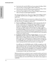
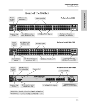
... the Series 2600-PWR Switches. 1-1 Use only one (T or M) for each Gigabit port Power Fault hp procurve switch 2626-PWR J8164A PoE Status RPS Act EPS LED Mode FDx Fan Spd Test PoE Reset Clear Spd mode: off = 10 Mbps, flash = 100 Mbps, on = 1000 Mbps ProCurve ... Clear *Spd mode: off = 10 Mbps, flash = 100 Mbps, on = 1000 Mbps Console ProCurve Switch 2600-8-PWR with Gigabit Uplink (J8762A) PoE-Integrated 10/100-TX Ports (1 - 8) — (Ports are HP Auto-MDIX) Link 1 Mode 2 3 4 Link 5 Mode 6 7 8 Dual-Personality Port: 10/100/1000-T (T) or Mini-GBIC (M) (Port...
... the Series 2600-PWR Switches. 1-1 Use only one (T or M) for each Gigabit port Power Fault hp procurve switch 2626-PWR J8164A PoE Status RPS Act EPS LED Mode FDx Fan Spd Test PoE Reset Clear Spd mode: off = 10 Mbps, flash = 100 Mbps, on = 1000 Mbps ProCurve ... Clear *Spd mode: off = 10 Mbps, flash = 100 Mbps, on = 1000 Mbps Console ProCurve Switch 2600-8-PWR with Gigabit Uplink (J8762A) PoE-Integrated 10/100-TX Ports (1 - 8) — (Ports are HP Auto-MDIX) Link 1 Mode 2 3 4 Link 5 Mode 6 7 8 Dual-Personality Port: 10/100/1000-T (T) or Mini-GBIC (M) (Port...
User Manual
Page 10
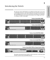
...to those devices, and you can build a switched network infrastructure by connecting the switch to hubs, other for Power over Ethernet (PoE) power: ■ Power-over existing LAN cabling, without needing to modify the existing Ethernet infrastructure. Introducing the Switch Introducing the Switch... offer full network management capabilities. 1-2 The Series 2600-PWR Switches incorporate two additional features. For further information regarding PoE power, see the PoE Planning and Implementation Guide, which is on the documentation CD that came with the Switch 2650-PWR, the additional ...
...to those devices, and you can build a switched network infrastructure by connecting the switch to hubs, other for Power over Ethernet (PoE) power: ■ Power-over existing LAN cabling, without needing to modify the existing Ethernet infrastructure. Introducing the Switch Introducing the Switch... offer full network management capabilities. 1-2 The Series 2600-PWR Switches incorporate two additional features. For further information regarding PoE power, see the PoE Planning and Implementation Guide, which is on the documentation CD that came with the Switch 2650-PWR, the additional ...
User Manual
Page 11
... Clear *Spd mode: off = 10 Mbps, flash = 100 Mbps, on = 1000 Mbps Console Reset and Clear buttons LED Mode select button and indicator LEDs PoE-Integrated 10/100-TX Ports (1 - 8) — (Ports are IEEE Auto MDI/MDI-X) 48 ! Use only one (T or M) for Port 9 10/100Base-TX RJ-45 ports1... 2 Spd mode: off = 10 Mbps, flash = 100 Mbps, on = 1000 Mbps 12 14 PoE-Ready 10/100Base-TX Ports (1 - 48) 24 26 49 M 50 M MiniGBIC Ports 36 38 (all 10/100Base-TX ports are HP Auto-MDIX, Gig-T ports are HP Auto-MDIX) Link 1 Mode 2 3 4 Link 5 Mode 6 7 8 Dual-Personality Port: 10/100/...
... Clear *Spd mode: off = 10 Mbps, flash = 100 Mbps, on = 1000 Mbps Console Reset and Clear buttons LED Mode select button and indicator LEDs PoE-Integrated 10/100-TX Ports (1 - 8) — (Ports are IEEE Auto MDI/MDI-X) 48 ! Use only one (T or M) for Port 9 10/100Base-TX RJ-45 ports1... 2 Spd mode: off = 10 Mbps, flash = 100 Mbps, on = 1000 Mbps 12 14 PoE-Ready 10/100Base-TX Ports (1 - 48) 24 26 49 M 50 M MiniGBIC Ports 36 38 (all 10/100Base-TX ports are HP Auto-MDIX, Gig-T ports are HP Auto-MDIX) Link 1 Mode 2 3 4 Link 5 Mode 6 7 8 Dual-Personality Port: 10/100/...
User Manual
Page 13
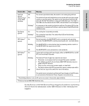
...be blinking simultaneously. Connected to an External Power Supply or the EPS cable is connected but cannot communicate with it is oversubscribed (not enough PoE power available). • The software on briefly when you have power cycled or reset the switch. See the ProCurve 600/610 External Power... and initialization are in progress after you "hot swap" a mini-GBIC into the switch; The External Power Supply has experienced a fault: • PoE power is hot swapped. The cooling fan has failed. EPS Status 2 (green) Off On Blinking Off The 600 RPS/EPS is not connected or ...
...be blinking simultaneously. Connected to an External Power Supply or the EPS cable is connected but cannot communicate with it is oversubscribed (not enough PoE power available). • The software on briefly when you have power cycled or reset the switch. See the ProCurve 600/610 External Power... and initialization are in progress after you "hot swap" a mini-GBIC into the switch; The External Power Supply has experienced a fault: • PoE power is hot swapped. The cooling fan has failed. EPS Status 2 (green) Off On Blinking Off The 600 RPS/EPS is not connected or ...
User Manual
Page 15
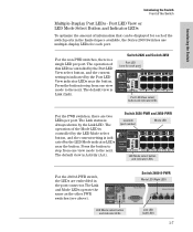
... view is Link (Lnk). Switch 2626-PWR and 2650-PWR Link LED (port number) Mode LED Power Fault hp procurve 1 3 5 7 switch 2650-PWR 2 1 4 6 8 J8165A PoE Status RPS Act EPS LED Mode FDx Fan Spd Test PoE Reset Clear 2 Spd mode: off = 10 Mbps, flash = 100 Mbps, 9 10 on = 1000 LED Mode select button...
... view is Link (Lnk). Switch 2626-PWR and 2650-PWR Link LED (port number) Mode LED Power Fault hp procurve 1 3 5 7 switch 2650-PWR 2 1 4 6 8 J8165A PoE Status RPS Act EPS LED Mode FDx Fan Spd Test PoE Reset Clear 2 Spd mode: off = 10 Mbps, flash = 100 Mbps, 9 10 on = 1000 LED Mode select button...

User Manual
Page 16
... not receiving signal or sufficient light. Series 2600-PWR Switches LED Mode Act indicator LEDs (4 green LEDs) FDx Indicates the Port Mode LEDs are providing PoE power to the connected device. 1 The blinking behavior is an on/off cycle once every 0.8 seconds, approximately. 1-8 Otherwise, the port may have... with the Fault LED, the corresponding port has failed its self test. Spd Indicates the Port Mode LEDs are in full-duplex mode. PoE Indicates the Port Mode LEDs are lit for ports that the Port LEDs are displaying the connection speed at which each port is operating: ...
... not receiving signal or sufficient light. Series 2600-PWR Switches LED Mode Act indicator LEDs (4 green LEDs) FDx Indicates the Port Mode LEDs are providing PoE power to the connected device. 1 The blinking behavior is an on/off cycle once every 0.8 seconds, approximately. 1-8 Otherwise, the port may have... with the Fault LED, the corresponding port has failed its self test. Spd Indicates the Port Mode LEDs are in full-duplex mode. PoE Indicates the Port Mode LEDs are lit for ports that the Port LEDs are displaying the connection speed at which each port is operating: ...
User Manual
Page 19
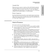
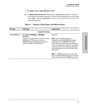
...3af compliant and provide up to 15.4W per port to power IP phones, wireless access points, web cameras, and more information, see the POE Planning and Implementation Guide, which can be made using the serial cable supplied with each switch's 8000address forwarding table, (with configurable address aging ...work. ■ automatic learning of the Series 2600 Switches include: ■ 8, 24, or 48 auto-sensing 10/100Base-TX RJ-45 ports with HP Auto-MDIX. ■ dual-personality ports-either 50 or 60 Hz. For more . Power Connector The Series 2600 Switches do not have a power switch...
...3af compliant and provide up to 15.4W per port to power IP phones, wireless access points, web cameras, and more information, see the POE Planning and Implementation Guide, which can be made using the serial cable supplied with each switch's 8000address forwarding table, (with configurable address aging ...work. ■ automatic learning of the Series 2600 Switches include: ■ 8, 24, or 48 auto-sensing 10/100Base-TX RJ-45 ports with HP Auto-MDIX. ■ dual-personality ports-either 50 or 60 Hz. For more . Power Connector The Series 2600 Switches do not have a power switch...
User Manual
Page 25
...-through or crossover twisted-pair cables for 1000 Mbps operation. Note: For 1000 Mbps operation, all four wire pairs are used for data transmission, therefore PoE is recommended. 100 meters Note: The Series 2600 Switches are compatible with the IEEE 802.3ab standard including the "Auto MDI/MDI-X" feature, which allows...
...-through or crossover twisted-pair cables for 1000 Mbps operation. Note: For 1000 Mbps operation, all four wire pairs are used for data transmission, therefore PoE is recommended. 100 meters Note: The Series 2600 Switches are compatible with the IEEE 802.3ab standard including the "Auto MDI/MDI-X" feature, which allows...
User Manual
Page 30
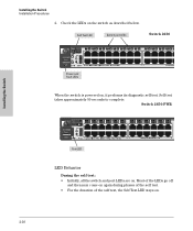
... the Switch Installation Procedures 2. Self test takes approximately 50 seconds to complete. Switch 2650-PWR Power Fault hp procurve 1 3 5 7 switch 2650-PWR 2 1 4 6 8 J8165A PoE Status RPS Act EPS LED Mode FDx Fan Spd Test PoE Reset Clear 2 Spd mode: off and then may come on again during phases of the self test.... 10 Mbps, flash = 100 Mbps, 9 11 10 12 on = 1000 Mbps 13 14 11 13 12 14 15 17 19 21 16 18 20 22 PoE-Ready 10/100Base-TX Ports (1 - 48) 23 Link|M 24 23 24 Test LED LED Behavior During the self test: • Initially, all the switch...
... the Switch Installation Procedures 2. Self test takes approximately 50 seconds to complete. Switch 2650-PWR Power Fault hp procurve 1 3 5 7 switch 2650-PWR 2 1 4 6 8 J8165A PoE Status RPS Act EPS LED Mode FDx Fan Spd Test PoE Reset Clear 2 Spd mode: off and then may come on again during phases of the self test.... 10 Mbps, flash = 100 Mbps, 9 11 10 12 on = 1000 Mbps 13 14 11 13 12 14 15 17 19 21 16 18 20 22 PoE-Ready 10/100Base-TX Ports (1 - 48) 23 Link|M 24 23 24 Test LED LED Behavior During the self test: • Initially, all the switch...

User Manual
Page 41
... "Switch Ports and Network Cables", for the Series 2600PWR Switches and specific other ProCurve switches. For the Switch 2650-PWR the external PoE power is additional power made available to a higher priority switch. The 600 RPS/EPS is an unmanaged power supply that only provides ...connected to the port, the port LED for more information. ■ External Power-over-Ethernet (PoE) power to two switch products. For further information regarding the 600 RPS/EPS PoE capabilities, see "Diagnosing with your switch. Should the internal switch power supply fail, power will ...
... "Switch Ports and Network Cables", for the Series 2600PWR Switches and specific other ProCurve switches. For the Switch 2650-PWR the external PoE power is additional power made available to a higher priority switch. The 600 RPS/EPS is an unmanaged power supply that only provides ...connected to the port, the port LED for more information. ■ External Power-over-Ethernet (PoE) power to two switch products. For further information regarding the 600 RPS/EPS PoE capabilities, see "Diagnosing with your switch. Should the internal switch power supply fail, power will ...

User Manual
Page 42
...end devices connected to the documentation that came with your switch. In this power at a given time. It is important to understand the PoE power requirements of the six supplied RPS cables. If a switch with the RPS/EPS. The 600 RPS/EPS can provide redundant +12V...length. 2-22 For more devices fail, priority goes to the switch within 1 millisecond. For further information regarding the 600 RPS/EPS PoE capabilities, see the PoE Planning and Implementation Guide and the ProCurve 600/610 External Power Supplies Installation and Getting Started Guide, which can provide a maximum of...
...end devices connected to the documentation that came with your switch. In this power at a given time. It is important to understand the PoE power requirements of the six supplied RPS cables. If a switch with the RPS/EPS. The 600 RPS/EPS can provide redundant +12V...length. 2-22 For more devices fail, priority goes to the switch within 1 millisecond. For further information regarding the 600 RPS/EPS PoE capabilities, see the PoE Planning and Implementation Guide and the ProCurve 600/610 External Power Supplies Installation and Getting Started Guide, which can provide a maximum of...

User Manual
Page 43
... Device Connected Power Status Line: 50/60 Hz. 10 0 - 240 V~ 9.1A (9,1A) The following graphic shows an example of the back of the device for PoE applications. should never happen Switch is connected, RPS is available but not required RPS is powering the connected device RPS/EPS port is in fault...
... Device Connected Power Status Line: 50/60 Hz. 10 0 - 240 V~ 9.1A (9,1A) The following graphic shows an example of the back of the device for PoE applications. should never happen Switch is connected, RPS is available but not required RPS is powering the connected device RPS/EPS port is in fault...

User Manual
Page 44
... as a redundant AC power supply. R6 E1 EPS 1 EPS 2 E2 Device Connected Power Status Line: 50/60 Hz. 10 0 - 240 V~ 9.1A (9,1A) Console EPS Input HP ProCurve RPS Input 12V 7.5A Switch RPS output port Line 50/60 Hz. 100-240 V~ 7.5 A RPS input port Installing the Switch 2-24 EPS Power: 50V...
... as a redundant AC power supply. R6 E1 EPS 1 EPS 2 E2 Device Connected Power Status Line: 50/60 Hz. 10 0 - 240 V~ 9.1A (9,1A) Console EPS Input HP ProCurve RPS Input 12V 7.5A Switch RPS output port Line 50/60 Hz. 100-240 V~ 7.5 A RPS input port Installing the Switch 2-24 EPS Power: 50V...

User Manual
Page 46
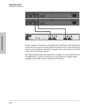
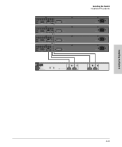
...used. R6 E1 EPS 1 EPS 2 E2 Device Connected Power Status Line: 50/60 Hz. 100 -240 V~ 9.1A (9,1A) Switch EPS output Console EPS Input HP ProCurve RPS Input 12V 7.5A EPS input port Line 50/60 Hz. 100-240 V~ 7.5 A Installing the Switch 2-26 R2 R3 R4 RPS 3 RPS 4 ...RPS 5 R5 RPS 6 EPS Power: 50V 370W total for PoE applications. Lowest-numbered port has priority. Installing the Switch Installation Procedures The following illustration demonstrates an example of connectivity between an RPS/EPS device and...
...used. R6 E1 EPS 1 EPS 2 E2 Device Connected Power Status Line: 50/60 Hz. 100 -240 V~ 9.1A (9,1A) Switch EPS output Console EPS Input HP ProCurve RPS Input 12V 7.5A EPS input port Line 50/60 Hz. 100-240 V~ 7.5 A Installing the Switch 2-26 R2 R3 R4 RPS 3 RPS 4 ...RPS 5 R5 RPS 6 EPS Power: 50V 370W total for PoE applications. Lowest-numbered port has priority. Installing the Switch Installation Procedures The following illustration demonstrates an example of connectivity between an RPS/EPS device and...
User Manual
Page 47
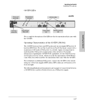
... Documentation CD-ROM that came with your switch and the documentation that came with the 610 EPS. For further information regarding the 610 EPS PoE capabilities, see the documentation that came with the 610 EPS. Operating Characteristics of the 610 EPS (J8169A) The 610 EPS does not have... B. Installing the Switch 610 EPS LEDs Installing the Switch Installation Procedures Power and Fault LEDs Backup Power Port LEDs EPS Port LEDs 610 EPS hp procurve 610 eps J8169A Pow er Fault Internal Power Status Fan/Temp Status Fan/Temp Status flash = Temperature too high Fan/Temp Status +...
... Documentation CD-ROM that came with your switch and the documentation that came with the 610 EPS. For further information regarding the 610 EPS PoE capabilities, see the documentation that came with the 610 EPS. Operating Characteristics of the 610 EPS (J8169A) The 610 EPS does not have... B. Installing the Switch 610 EPS LEDs Installing the Switch Installation Procedures Power and Fault LEDs Backup Power Port LEDs EPS Port LEDs 610 EPS hp procurve 610 eps J8169A Pow er Fault Internal Power Status Fan/Temp Status Fan/Temp Status flash = Temperature too high Fan/Temp Status +...
User Manual
Page 48
...to both ports of a pair, both ports of pair A for example, then each switch receives 204 watts. EPS Ports Pair B (408 W total for PoE applications) EPS A1 A1 Device Connected Power EPS A2 A2 Status EPS Ports: 50V 8.3A max each. Installing the Switch Installation Procedures 50 V 16 A ...50 V 16 A RPS 12 V 7.5 A RPS 12 V 7.5 A Line: 50/60 Hz. 100-240 V~ 7.5 A Line: 50/60 Hz. 100-240 V~ 7.5 A hp procurve 610 eps J8169A Pow er Fault Internal Power Status Fan/Temp Status Fan/Temp Status flash = Temperature too high Fan/Temp Status + Fault flash...
...to both ports of a pair, both ports of pair A for example, then each switch receives 204 watts. EPS Ports Pair B (408 W total for PoE applications) EPS A1 A1 Device Connected Power EPS A2 A2 Status EPS Ports: 50V 8.3A max each. Installing the Switch Installation Procedures 50 V 16 A ...50 V 16 A RPS 12 V 7.5 A RPS 12 V 7.5 A Line: 50/60 Hz. 100-240 V~ 7.5 A Line: 50/60 Hz. 100-240 V~ 7.5 A hp procurve 610 eps J8169A Pow er Fault Internal Power Status Fan/Temp Status Fan/Temp Status flash = Temperature too high Fan/Temp Status + Fault flash...
User Manual
Page 49
EPS Ports Pair B (408 W total for PoE applications) EPS A1 A1 Device Connected Power EPS A2 A2 Status EPS Ports: 50V 8.3A max each. 50 V 16 ... 50/60 Hz. 100-240 V~ 7.5 A Line: 50/60 Hz. 100-240 V~ 7.5 A Line: 50/60 Hz. 100-240 V~ 7.5 A hp procurve 610 eps J8169A Pow er Fault Internal Power Status Fan/Temp Status Fan/Temp Status flash = Temperature too high Fan/Temp Status + Fault flash... failure Backup Power Ports Status In Ready Out Ready EPS Ports Pair A (408 W total for PoE applications) EPS B1 B1 Device Connected Power EPS B2 B2 Status Installing the Switch 2-29
EPS Ports Pair B (408 W total for PoE applications) EPS A1 A1 Device Connected Power EPS A2 A2 Status EPS Ports: 50V 8.3A max each. 50 V 16 ... 50/60 Hz. 100-240 V~ 7.5 A Line: 50/60 Hz. 100-240 V~ 7.5 A Line: 50/60 Hz. 100-240 V~ 7.5 A hp procurve 610 eps J8169A Pow er Fault Internal Power Status Fan/Temp Status Fan/Temp Status flash = Temperature too high Fan/Temp Status + Fault flash... failure Backup Power Ports Status In Ready Out Ready EPS Ports Pair A (408 W total for PoE applications) EPS B1 B1 Device Connected Power EPS B2 B2 Status Installing the Switch 2-29

User Manual
Page 56
...in the above illustration the IP telephones can send and receive data through or crossover twisted-pair cables. As a Desktop Switch Implementing PoE 600 RPS/EPS Twisted-pair straight-through or crossover cables 2650-PWR Server Installing the Switch Wireless Access Point IP Telephones PCs and peripherals... The Series 2600-PWR Switches are also designed to be used because of the "HP Auto-MDIX" and "IEEE Auto MDI/MDI-X" features on the Series 2600PWR Switches. 2-36 Therefore the phone receives voice and power ...
...in the above illustration the IP telephones can send and receive data through or crossover twisted-pair cables. As a Desktop Switch Implementing PoE 600 RPS/EPS Twisted-pair straight-through or crossover cables 2650-PWR Server Installing the Switch Wireless Access Point IP Telephones PCs and peripherals... The Series 2600-PWR Switches are also designed to be used because of the "HP Auto-MDIX" and "IEEE Auto MDI/MDI-X" features on the Series 2600PWR Switches. 2-36 Therefore the phone receives voice and power ...