
User Manual
Page 5
Verify the Switch Passes Self Test 2-9 LED Behavior 2-10 4. Port LED View or LED Mode Select Button and Indicator LEDs 1-7 Reset Button 1-9 Clear Button 1-9 Back of the Switch 1-3 Network Ports 1-4 LEDs 1-4 Port LEDs 1-6 Multiple-Display Port LEDs - Installing or Removing mini-GBICs 2-7 3. Mount the Switch 2-11 ...
Verify the Switch Passes Self Test 2-9 LED Behavior 2-10 4. Port LED View or LED Mode Select Button and Indicator LEDs 1-7 Reset Button 1-9 Clear Button 1-9 Back of the Switch 1-3 Network Ports 1-4 LEDs 1-4 Port LEDs 1-6 Multiple-Display Port LEDs - Installing or Removing mini-GBICs 2-7 3. Mount the Switch 2-11 ...
User Manual
Page 7
Testing the Switch by Resetting It 4-9 Checking the Switch LEDs 4-9 Checking Console Messages 4-9 Testing Twisted-Pair Cabling 4-10 Testing Switch-to-Device Network Communications 4-10 Testing End-to-End Network Communications 4-10 Restoring the Factory Default Configuration 4-11 Downloading New Switch Software 4-12 HP Customer Support Services 4-12 Before Calling Support 4-12 A Switch...
Testing the Switch by Resetting It 4-9 Checking the Switch LEDs 4-9 Checking Console Messages 4-9 Testing Twisted-Pair Cabling 4-10 Testing Switch-to-Device Network Communications 4-10 Testing End-to-End Network Communications 4-10 Restoring the Factory Default Configuration 4-11 Downloading New Switch Software 4-12 HP Customer Support Services 4-12 Before Calling Support 4-12 A Switch...
User Manual
Page 9
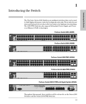
... switches will be used to as the Series 2600 Switches and the Series 2600-PWR Switches. 1-1 ProCurve Switch 2650 (J4899B) ProCurve Switch 2626 (J4900B) ProCurve Switch 2650-PWR (J8165A) hp procurve 1 3 5 7 9 11 13 15 17 19 21 23 Link|Mode 25 27 29 31 33 35 37 39 41 43 45... 48 11 13 23 25 35 37 47 J8165A PoE Gig-T Ports Power Fault Status RPS Act EPS LED Mode FDx Fan Spd Test PoE Reset Clear 2 Spd mode: off = 10 Mbps, flash = 100 Mbps, on = 1000 Mbps ProCurve Switch 2626-PWR (J8164A) Link|Mode 1 2 1 2 3 5 7 9 4 6 8 10 PoE-Ready 10/...
... switches will be used to as the Series 2600 Switches and the Series 2600-PWR Switches. 1-1 ProCurve Switch 2650 (J4899B) ProCurve Switch 2626 (J4900B) ProCurve Switch 2650-PWR (J8165A) hp procurve 1 3 5 7 9 11 13 15 17 19 21 23 Link|Mode 25 27 29 31 33 35 37 39 41 43 45... 48 11 13 23 25 35 37 47 J8165A PoE Gig-T Ports Power Fault Status RPS Act EPS LED Mode FDx Fan Spd Test PoE Reset Clear 2 Spd mode: off = 10 Mbps, flash = 100 Mbps, on = 1000 Mbps ProCurve Switch 2626-PWR (J8164A) Link|Mode 1 2 1 2 3 5 7 9 4 6 8 10 PoE-Ready 10/...
User Manual
Page 11
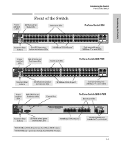
... and Fault LEDs Self Test and Fan Status LEDs Switch port LEDs Introducing the Switch Front of the Switch ProCurve Switch 2650 Introducing the Switch Reset and Clear buttons Port LED View select button and indicator LEDs 10/100Base-TX RJ-45 ports1 Dual-personality ports (1000Base-T2 or mini-GBIC...) Power and Fault LEDs RPS, EPS, Fan and Test Status LEDs Switch port LEDs ProCurve Switch 2650-PWR hp procurve 1 3 5 7 9 11 13 15 17 19 21 23 Link|Mode 25 27 29 31 33 35 37 39 41 43 45 47 switch 2650-PWR...
... and Fault LEDs Self Test and Fan Status LEDs Switch port LEDs Introducing the Switch Front of the Switch ProCurve Switch 2650 Introducing the Switch Reset and Clear buttons Port LED View select button and indicator LEDs 10/100Base-TX RJ-45 ports1 Dual-personality ports (1000Base-T2 or mini-GBIC...) Power and Fault LEDs RPS, EPS, Fan and Test Status LEDs Switch port LEDs ProCurve Switch 2650-PWR hp procurve 1 3 5 7 9 11 13 15 17 19 21 23 Link|Mode 25 27 29 31 33 35 37 39 41 43 45 47 switch 2650-PWR...
User Manual
Page 12
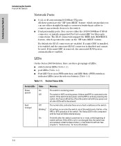
... to connect any network devices to the switch. If a mini-GBIC is installed, it is enabled and the associated RJ-45 connector is on or reset, at the beginning of LEDs: ■ switch status LEDs (Table 1-1) ■ port LEDs (Table 1-2) ■ Port LED View (non-PWR switches) and LED Mode... See chapter 4, "Troubleshooting" for the component with the fault will be off and the switch will still have the "HP Auto MDIX" feature, which operates the same as the "HP Auto-MDIX" feature. Introducing the Switch Introducing the Switch Front of the switch. All these ports have power and all ...
... to connect any network devices to the switch. If a mini-GBIC is installed, it is enabled and the associated RJ-45 connector is on or reset, at the beginning of LEDs: ■ switch status LEDs (Table 1-1) ■ port LEDs (Table 1-2) ■ Port LED View (non-PWR switches) and LED Mode... See chapter 4, "Troubleshooting" for the component with the fault will be off and the switch will still have the "HP Auto MDIX" feature, which operates the same as the "HP Auto-MDIX" feature. Introducing the Switch Introducing the Switch Front of the switch. All these ports have power and all ...
User Manual
Page 13
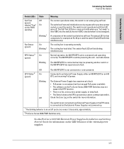
... . Introducing the Switch Introducing the Switch Front of the Switch Switch LEDs Self Test (green) labeled "Test" on briefly when you have power cycled or reset the switch. the mini-GBIC is hot swapped. An 600 RPS/EPS unit is operating normally. The switch self test and initialization are in progress...
... . Introducing the Switch Introducing the Switch Front of the Switch Switch LEDs Self Test (green) labeled "Test" on briefly when you have power cycled or reset the switch. the mini-GBIC is hot swapped. An 600 RPS/EPS unit is operating normally. The switch self test and initialization are in progress...
User Manual
Page 15
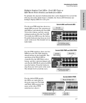
... to the next. Switch 2626-PWR and 2650-PWR Link LED (port number) Mode LED Power Fault hp procurve 1 3 5 7 switch 2650-PWR 2 1 4 6 8 J8165A PoE Status RPS Act EPS LED Mode FDx Fan Spd Test PoE Reset Clear 2 Spd mode: off = 10 Mbps, flash = 100 Mbps, 9 10 on = 1000 LED Mode select button...
... to the next. Switch 2626-PWR and 2650-PWR Link LED (port number) Mode LED Power Fault hp procurve 1 3 5 7 switch 2650-PWR 2 1 4 6 8 J8165A PoE Status RPS Act EPS LED Mode FDx Fan Spd Test PoE Reset Clear 2 Spd mode: off = 10 Mbps, flash = 100 Mbps, 9 10 on = 1000 LED Mode select button...
User Manual
Page 17
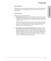
Use this manual. 1-9 This button is provided for your convenience, but its presence means that if you are concerned with the Reset button in a secure location, such as a locked wiring closet. ■ Restoring Factory Default Configuration - When pressed with the security of the switch ... have made through the switch console, the web browser interface, and SNMP management are removed, and the factory default configuration is restored to reset the switch while it is powered on page 11, "Troubleshooting" of this feature if you may have misplaced the password and need console access...
Use this manual. 1-9 This button is provided for your convenience, but its presence means that if you are concerned with the Reset button in a secure location, such as a locked wiring closet. ■ Restoring Factory Default Configuration - When pressed with the security of the switch ... have made through the switch console, the web browser interface, and SNMP management are removed, and the factory default configuration is restored to reset the switch while it is powered on page 11, "Troubleshooting" of this feature if you may have misplaced the password and need console access...
User Manual
Page 30
... test takes approximately 50 seconds to complete. Installing the Switch Installation Procedures 2. Switch 2650-PWR Power Fault hp procurve 1 3 5 7 switch 2650-PWR 2 1 4 6 8 J8165A PoE Status RPS Act EPS LED Mode FDx Fan Spd Test PoE Reset Clear 2 Spd mode: off and then may come on again during phases of the self test...
... test takes approximately 50 seconds to complete. Installing the Switch Installation Procedures 2. Switch 2650-PWR Power Fault hp procurve 1 3 5 7 switch 2650-PWR 2 1 4 6 8 J8165A PoE Status RPS Act EPS LED Mode FDx Fan Spd Test PoE Reset Clear 2 Spd mode: off and then may come on again during phases of the self test...

User Manual
Page 71
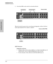
...tested when they are snug. hardware failure Call your HP-authorized LAN dealer, or use the electronic support services from is still not on the front of the mini-GBICs supported by the switch. All assistance. Then, reset the switch. If the error indication reoccurs, one... of the switch, or by plugging another device into an sure these connections are "hot-swapped"-installed or changed while the switch is powered on indefinitely. ➌ The switch has 1. Contact your HP-authorized LAN ...
...tested when they are snug. hardware failure Call your HP-authorized LAN dealer, or use the electronic support services from is still not on the front of the mini-GBICs supported by the switch. All assistance. Then, reset the switch. If the error indication reoccurs, one... of the switch, or by plugging another device into an sure these connections are "hot-swapped"-installed or changed while the switch is powered on indefinitely. ➌ The switch has 1. Contact your HP-authorized LAN ...

User Manual
Page 75
... and Self Test LEDs on the front of the switch Power cycling the switch and pressing the Reset button both cause the switch to perform its power-on self test, which can reset the switch to run at 9600 baud, and with the switch. If these LEDs stay on... on interpreting the LED patterns. Troubleshooting Hardware Diagnostic Tests Hardware Diagnostic Tests Testing the Switch by Resetting It If you believe the switch is reset. To reset a switch, either: ■ unplug and plug in chapter 2 under step 7, Connect a Console to the Switch connect a PC running a VT-100 terminal emulator program ...
... and Self Test LEDs on the front of the switch Power cycling the switch and pressing the Reset button both cause the switch to perform its power-on self test, which can reset the switch to run at 9600 baud, and with the switch. If these LEDs stay on... on interpreting the LED patterns. Troubleshooting Hardware Diagnostic Tests Hardware Diagnostic Tests Testing the Switch by Resetting It If you believe the switch is reset. To reset a switch, either: ■ unplug and plug in chapter 2 under step 7, Connect a Console to the Switch connect a PC running a VT-100 terminal emulator program ...
User Manual
Page 77
...settings for example, configuration of the original problem, you have made from the console command prompt. 4-11 Troubleshooting For both the Reset and Clear buttons on . 2. The switch will then complete its self test and begin operating with your troubleshooting process on the... pointed objects, simultaneously press both the save the switch configuration prior to the factory default settings. To execute the factory default reset on the Documentation CD-ROM that you can restore the saved configuration to the factory default settings. This clears any passwords, ...
...settings for example, configuration of the original problem, you have made from the console command prompt. 4-11 Troubleshooting For both the Reset and Clear buttons on . 2. The switch will then complete its self test and begin operating with your troubleshooting process on the... pointed objects, simultaneously press both the save the switch configuration prior to the factory default settings. To execute the factory default reset on the Documentation CD-ROM that you can restore the saved configuration to the factory default settings. This clears any passwords, ...
User Manual
Page 109
... B-5 B back of non-standard cables ... 4-2 fiber-optic, specifications ... A-2 auto MDI/MDI-X operation ... A-2 buttons Clear button ... 1-9 Reset button ... 1-9 C cabinet mounting the switch in -band access ... 2-30 BTU ratings ... B-2 1000Base-SX connections ... 2-6 fiber-optic cable specifications...2-5 serial, for in ... 2-11 cable EPS cable length ... 2-22 RPS cable length ... 2-22 cable length specifications ... B-7, B-9 HP Auto-MDIX feature ... B-2 1000Base-LX connections ... 2-6 fiber-optic cable specifications ... B-2 1000Base-T connections ... 2-5 connecting cables to switch ...
... B-5 B back of non-standard cables ... 4-2 fiber-optic, specifications ... A-2 auto MDI/MDI-X operation ... A-2 buttons Clear button ... 1-9 Reset button ... 1-9 C cabinet mounting the switch in -band access ... 2-30 BTU ratings ... B-2 1000Base-SX connections ... 2-6 fiber-optic cable specifications...2-5 serial, for in ... 2-11 cable EPS cable length ... 2-22 RPS cable length ... 2-22 cable length specifications ... B-7, B-9 HP Auto-MDIX feature ... B-2 1000Base-LX connections ... 2-6 fiber-optic cable specifications ... B-2 1000Base-T connections ... 2-5 connecting cables to switch ...
User Manual
Page 111
.../100Base-TX ports ... 1-3 Clear button ... 1-9 description ... 1-3 dual-personality ports ... 1-4 LEDs ... 1-4 network ports ... 1-4 Reset button ... 1-9 full-duplex fixed configuration effects on network connections ... 4-1 full-duplex operation of mini-GBICs ... 2-7 G Gigabit-LH ... test ... 2-11 Self Test ... 1-5 behavior during self test ... 2-11 behaviors ... 1-4 blinking definition ... 1-5-1-6, 1-8 location on ... 2-19 HP Auto-MDIX feature description ... B-7, B-9 MDI-X to a power source ... 2-19 horizontal surface mounting ... 2-19 location considerations ... 2-6 network cable ...
.../100Base-TX ports ... 1-3 Clear button ... 1-9 description ... 1-3 dual-personality ports ... 1-4 LEDs ... 1-4 network ports ... 1-4 Reset button ... 1-9 full-duplex fixed configuration effects on network connections ... 4-1 full-duplex operation of mini-GBICs ... 2-7 G Gigabit-LH ... test ... 2-11 Self Test ... 1-5 behavior during self test ... 2-11 behaviors ... 1-4 blinking definition ... 1-5-1-6, 1-8 location on ... 2-19 HP Auto-MDIX feature description ... B-7, B-9 MDI-X to a power source ... 2-19 horizontal surface mounting ... 2-19 location considerations ... 2-6 network cable ...

User Manual
Page 112
...tools diagnostics with the Clear button ... 3-4 if you lose the password ... 3-4 passwords, deleting ... 1-9 physical specifications, switch ... B-2 HP Auto-MDIX feature ... Index mini-GBICs full-duplex operation ... 2-7 slot, location on switch ... 1-3 mounting the switch in ... 2-...11 Redundant and External Power Supply ... 1-2 RPS/EPS ... 2-21 Redundant Power Supply ... 2-21 regulatory statements ... C-8 Reset button description ... 1-9 location on a wall ... 2-16 precautions ... 2-16 Multiple-Display Port LEDs ... 1-7 N network cables 1000Base-LH connections ......
...tools diagnostics with the Clear button ... 3-4 if you lose the password ... 3-4 passwords, deleting ... 1-9 physical specifications, switch ... B-2 HP Auto-MDIX feature ... Index mini-GBICs full-duplex operation ... 2-7 slot, location on switch ... 1-3 mounting the switch in ... 2-...11 Redundant and External Power Supply ... 1-2 RPS/EPS ... 2-21 Redundant Power Supply ... 2-21 regulatory statements ... C-8 Reset button description ... 1-9 location on a wall ... 2-16 precautions ... 2-16 Multiple-Display Port LEDs ... 1-7 N network cables 1000Base-LH connections ......

User Manual
Page 113
... behavior ... 2-11 LED behavior during ... 2-10 Power LED behavior ... 2-11 Self Test LED ... 1-5 behavior during factory default reset ... 4-11 behavior during self test ... 2-10 serial cable for direct console connection ... 2-31 SFP ports ... 1-2 slots for troubleshooting... ... 4-10 twisted-pair cabling ... 4-10 tips for mini-GBICs location on horizontal surface ... 2-19 physical specifications ... resetting the switch factory default reset ... 4-11 location of Reset button ... 1-9 troubleshooting procedure ... 4-9 RPS/EPS ... 2-21 cables ... 2-22 connecting to a power source ... 2-19...
... behavior ... 2-11 LED behavior during ... 2-10 Power LED behavior ... 2-11 Self Test LED ... 1-5 behavior during factory default reset ... 4-11 behavior during self test ... 2-10 serial cable for direct console connection ... 2-31 SFP ports ... 1-2 slots for troubleshooting... ... 4-10 twisted-pair cabling ... 4-10 tips for mini-GBICs location on horizontal surface ... 2-19 physical specifications ... resetting the switch factory default reset ... 4-11 location of Reset button ... 1-9 troubleshooting procedure ... 4-9 RPS/EPS ... 2-21 cables ... 2-22 connecting to a power source ... 2-19...