
User Manual
Page 5
... the HP Procurve Series 2700 Switches Front of the Switch 1-2 Network Ports 1-2 Reset Button 1-2 LEDs 1-3 Mode LED View Button and Indicator LEDs 1-4 Back of the Switch 1-5 Power Connector 1-5 Features 1-6 Switch Operation Overview 1-7 Address Table Operation 1-7 2 Installing the Series 2700 Switches Included Parts 2-1 Installation Procedures 2-2 Summary 2-2 Installation Precautions 2-3 1. Prepare the Installation Site 2-4 2. Mount the Switch 2-7 Rack or Cabinet Mounting 2-7 Wall Mounting 2-10 Horizontal Surface Mounting 2-12 4. Connect the Network Cables 2-12 Using...
... the HP Procurve Series 2700 Switches Front of the Switch 1-2 Network Ports 1-2 Reset Button 1-2 LEDs 1-3 Mode LED View Button and Indicator LEDs 1-4 Back of the Switch 1-5 Power Connector 1-5 Features 1-6 Switch Operation Overview 1-7 Address Table Operation 1-7 2 Installing the Series 2700 Switches Included Parts 2-1 Installation Procedures 2-2 Summary 2-2 Installation Precautions 2-3 1. Prepare the Installation Site 2-4 2. Mount the Switch 2-7 Rack or Cabinet Mounting 2-7 Wall Mounting 2-10 Horizontal Surface Mounting 2-12 4. Connect the Network Cables 2-12 Using...

User Manual
Page 6
... Troubleshooting Tips 3-1 Diagnosing with the LEDs 3-3 Hardware Diagnostic Tests 3-4 Testing the Switch by Resetting It 3-4 Checking the Switch LEDs 3-4 Testing Twisted-Pair Cabling 3-5 Testing End-to-End Network Communications 3-5 HP Customer Support Services 3-5 A Specifications Physical A-1 Electrical A-1 Environmental A-1 Acoustic A-1 Connectors A-2 Safety A-2 B Switch Ports and Network Cables Switch Ports B-1 Twisted-Pair Cables B-1 Twisted-Pair Cable/Connector Pin-Outs B-3 Straight-Through Twisted-Pair Cable for 10 Mbps or 100 Mbps Network Connections B-4 Cable Diagram...
... Troubleshooting Tips 3-1 Diagnosing with the LEDs 3-3 Hardware Diagnostic Tests 3-4 Testing the Switch by Resetting It 3-4 Checking the Switch LEDs 3-4 Testing Twisted-Pair Cabling 3-5 Testing End-to-End Network Communications 3-5 HP Customer Support Services 3-5 A Specifications Physical A-1 Electrical A-1 Environmental A-1 Acoustic A-1 Connectors A-2 Safety A-2 B Switch Ports and Network Cables Switch Ports B-1 Twisted-Pair Cables B-1 Twisted-Pair Cable/Connector Pin-Outs B-3 Straight-Through Twisted-Pair Cable for 10 Mbps or 100 Mbps Network Connections B-4 Cable Diagram...

User Manual
Page 9
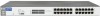
HP Procurve Switch 2708 (HP J4898A) hp procurve switch 2708 J4898A Power Fault Reset Spd mode: off = 10 Mbps flash = 100 Mbps on = 1000 Mbps Act FDx Spd Mode LED View 1 Link 1 Mode 2 2 3 3 10/100/1000Base-T Ports (all ports are IEEE Auto MDI/MDI-X) 4 5 4 5 6 6 7 7 8 8 HP Procurve Switch 2724 (HP J4897A) Power Fault hp procurve switch 2724 J4897A Reset Spd mode: off = 10 Mbps flash = 100 Mbps on = 1000 Mbps Act FDx Spd Mode LED View 1 2 3 4 5 6 Link 1 2 3 4 5 6 13 14 15 16 17 18 10/100/1000Base-T Ports Mode (all ports are...
HP Procurve Switch 2708 (HP J4898A) hp procurve switch 2708 J4898A Power Fault Reset Spd mode: off = 10 Mbps flash = 100 Mbps on = 1000 Mbps Act FDx Spd Mode LED View 1 Link 1 Mode 2 2 3 3 10/100/1000Base-T Ports (all ports are IEEE Auto MDI/MDI-X) 4 5 4 5 6 6 7 7 8 8 HP Procurve Switch 2724 (HP J4897A) Power Fault hp procurve switch 2724 J4897A Reset Spd mode: off = 10 Mbps flash = 100 Mbps on = 1000 Mbps Act FDx Spd Mode LED View 1 2 3 4 5 6 Link 1 2 3 4 5 6 13 14 15 16 17 18 10/100/1000Base-T Ports Mode (all ports are...

User Manual
Page 10
... HP Procurve Series 2700 Switches Introducing the HP Procurve Series 2700 Switches Front of the Switch Front of the Switch Power Fault LED LED hp procurve switch 2708 J4898A Power Fault Reset Spd mode: off = 10 Mbps flash = 100 Mbps on = 1000 Mbps Act FDx Spd Mode LED View 10/100/1000Base-T RJ-45 ports 1 Link 1 Mode 2 2 3 3 10/100/1000Base-T Ports (all ports are IEEE Auto MDI/MDI-X) 4 5 4 5 6 6 7 7 8 8 Reset button Mode LED View button and indicator LEDs Link and Mode LEDs for each port hp procurve switch 2724 J4897A Power Fault Reset Spd mode: off = 10 Mbps flash...
... HP Procurve Series 2700 Switches Introducing the HP Procurve Series 2700 Switches Front of the Switch Front of the Switch Power Fault LED LED hp procurve switch 2708 J4898A Power Fault Reset Spd mode: off = 10 Mbps flash = 100 Mbps on = 1000 Mbps Act FDx Spd Mode LED View 10/100/1000Base-T RJ-45 ports 1 Link 1 Mode 2 2 3 3 10/100/1000Base-T Ports (all ports are IEEE Auto MDI/MDI-X) 4 5 4 5 6 6 7 7 8 8 Reset button Mode LED View button and indicator LEDs Link and Mode LEDs for each port hp procurve switch 2724 J4897A Power Fault Reset Spd mode: off = 10 Mbps flash...

User Manual
Page 11
... the mode selected. Indicates that the port Mode LEDs are no active network cable is connected to the port • the port is not receiving a link signal Mode (green) Displays network activity information, or whether the port is enabled and receiving a link indication from the connected device. Introducing the HP Procurve Series 2700 Switches Introducing the HP Procurve Series 2700 Switches Front of switch self test. Link On (green - Fault Off (orange) On The normal state; One of two quick flashes followed...
... the mode selected. Indicates that the port Mode LEDs are no active network cable is connected to the port • the port is not receiving a link signal Mode (green) Displays network activity information, or whether the port is enabled and receiving a link indication from the connected device. Introducing the HP Procurve Series 2700 Switches Introducing the HP Procurve Series 2700 Switches Front of switch self test. Link On (green - Fault Off (orange) On The normal state; One of two quick flashes followed...

User Manual
Page 12
... this LED is controlled by the Mode LED View button, and the current setting is indicated by an off = 10 Mbps flash = 100 Mbps on = 1000 Mbps Act FDx Spd Mode LED View 1 Link 1 Mode 2 2 ■ If the Activity (Act) indicator LED is lit, the Mode LED for each port displays activity information for each of the switch ports, the Series 2700 Switches use a Mode LED for the port - Introducing the HP Procurve Series 2700 Switches Introducing the HP Procurve Series 2700 Switches...
... this LED is controlled by the Mode LED View button, and the current setting is indicated by an off = 10 Mbps flash = 100 Mbps on = 1000 Mbps Act FDx Spd Mode LED View 1 Link 1 Mode 2 2 ■ If the Activity (Act) indicator LED is lit, the Mode LED for each port displays activity information for each of the switch ports, the Series 2700 Switches use a Mode LED for the port - Introducing the HP Procurve Series 2700 Switches Introducing the HP Procurve Series 2700 Switches...

User Manual
Page 15
... port as "flooding". Forwarding, Filtering, Flooding. if the destination address is on a different port than the one on a port, the destination address will not yet be in the Series 2700 Switch's address table. The switch thereby isolates local traffic so the rest of that address are connected to forward or filter out the packet. Network Moves and Changes. Introducing the HP Procurve Series 2700 Switches Introducing the HP Procurve Series 2700 Switches Switch Operation Overview Switch Operation Overview Address Table Operation Address...
... port as "flooding". Forwarding, Filtering, Flooding. if the destination address is on a different port than the one on a port, the destination address will not yet be in the Series 2700 Switch's address table. The switch thereby isolates local traffic so the rest of that address are connected to forward or filter out the packet. Network Moves and Changes. Introducing the HP Procurve Series 2700 Switches Introducing the HP Procurve Series 2700 Switches Switch Operation Overview Switch Operation Overview Address Table Operation Address...

User Manual
Page 22
... Series 2700 Switches Installing the Series 2700 Switches Installation Procedures hp procurve switch 2708 J4898A Power Fault Reset Power and Fault LEDs Spd mode: off = 10 Mbps flash = 100 Mbps on = 1000 Mbps Act FDx Spd Mode LED View switch port LEDs 1 2 3 Link 1 2 3 4 Mode When the switch is described above, especially if the Fault LED stays on . • The port LEDs (Link and Mode) go into their normal operational mode: - LED Behavior: During the self test: • All the switch and port LEDs are not connected...
... Series 2700 Switches Installing the Series 2700 Switches Installation Procedures hp procurve switch 2708 J4898A Power Fault Reset Power and Fault LEDs Spd mode: off = 10 Mbps flash = 100 Mbps on = 1000 Mbps Act FDx Spd Mode LED View switch port LEDs 1 2 3 Link 1 2 3 4 Mode When the switch is described above, especially if the Fault LED stays on . • The port LEDs (Link and Mode) go into their normal operational mode: - LED Behavior: During the self test: • All the switch and port LEDs are not connected...

User Manual
Page 28
... can be used to a Power Source 1. Connect the Network Cables Connect the network cables, described under "Cabling Infrastructure" (page 2-4), from sliding on the surface. See "LED Behavior" on a table or other part of the switch. 4. Attach the rubber feet to the RJ-45 ports on the bottom of the switch within the embossed angled lines. Installing the Series 2700 Switches 2-12 You may want to secure the networking cables and switch power cord to...
... can be used to a Power Source 1. Connect the Network Cables Connect the network cables, described under "Cabling Infrastructure" (page 2-4), from sliding on the surface. See "LED Behavior" on a table or other part of the switch. 4. Attach the rubber feet to the RJ-45 ports on the bottom of the switch within the embossed angled lines. Installing the Series 2700 Switches 2-12 You may want to secure the networking cables and switch power cord to...

User Manual
Page 29
... network cable is connected to confirm a powered-on for the switch and for the connected device, the Link LED for the port should light to the port, see "Diagnosing with the LEDs" in chapter 3, "Troubleshooting". To disconnect: Press the small tab on the plug clicks into the RJ-45 jack until the tab on the plug and pull the plug out of the cable. Installing the Series...
... network cable is connected to confirm a powered-on for the switch and for the connected device, the Link LED for the port should light to the port, see "Diagnosing with the LEDs" in chapter 3, "Troubleshooting". To disconnect: Press the small tab on the plug clicks into the RJ-45 jack until the tab on the plug and pull the plug out of the cable. Installing the Series...

User Manual
Page 31
... will default to devices that all devices connected to the Series 2700 Switches' RJ-45 ports are configured to auto negotiate, or are configured to connect at full duplex, the device will not connect correctly to Auto, the switch will operate in compliance with the LEDs (page 3-3) ■ hardware diagnostic tests (page 3-4) ■ HP Customer Support Services (page 3-5) Basic Troubleshooting Tips Most problems are configured as "Auto". Make sure that have a fixed full-duplex configuration. Check for...
... will default to devices that all devices connected to the Series 2700 Switches' RJ-45 ports are configured to auto negotiate, or are configured to connect at full duplex, the device will not connect correctly to Auto, the switch will operate in compliance with the LEDs (page 3-3) ■ hardware diagnostic tests (page 3-4) ■ HP Customer Support Services (page 3-5) Basic Troubleshooting Tips Most problems are configured as "Auto". Make sure that have a fixed full-duplex configuration. Check for...

User Manual
Page 32
... Information Library section. 3-2 Troubleshooting For more information on the HP Procurve web site, http://www.hp.com/go / hpprocurve in appendix B, "Switch Ports and Network Cables" for pinouts and correct cable wiring. Between any time. A category 5 cable tester is shown at the end of chapter 2 in this book, and some topology configuration guidelines can be found on possible network problems and their solutions, refer to make sure...
... Information Library section. 3-2 Troubleshooting For more information on the HP Procurve web site, http://www.hp.com/go / hpprocurve in appendix B, "Switch Ports and Network Cables" for pinouts and correct cable wiring. Between any time. A category 5 cable tester is shown at the end of chapter 2 in this book, and some topology configuration guidelines can be found on possible network problems and their solutions, refer to make sure...

User Manual
Page 33
... the switch's power supply may have failed. Call your HP-authorized LAN dealer, or use the electronic support services from HP to the corresponding diagnostic tip on your switch for the diagnosis. See the Customer Support/Warranty booklet that indicate problem conditions. 1. Troubleshooting Diagnosing with the LEDs Diagnosing with the LEDs Table 3-1 shows LED patterns on the switch that came with your switch. 2. Solution 1. Refer to get assistance. Try power cycling the switch by...
... the switch's power supply may have failed. Call your HP-authorized LAN dealer, or use the electronic support services from HP to the corresponding diagnostic tip on your switch for the diagnosis. See the Customer Support/Warranty booklet that indicate problem conditions. 1. Troubleshooting Diagnosing with the LEDs Diagnosing with the LEDs Table 3-1 shows LED patterns on the switch that came with your switch. 2. Solution 1. Refer to get assistance. Try power cycling the switch by...

User Manual
Page 34
...; Press the reset button on the front of the switch Power cycling the switch and pressing the Reset button both powered on and operating correctly. • Verify that you continue to have problems, call your HP-authorized LAN dealer, or use the electronic support services from HP to get assistance. Troubleshooting Hardware Diagnostic Tests Tip Number ➌ Problem The network connection is not operating correctly, you can be used because of the switch's "Auto MDI/MDI...
...; Press the reset button on the front of the switch Power cycling the switch and pressing the Reset button both powered on and operating correctly. • Verify that you continue to have problems, call your HP-authorized LAN dealer, or use the electronic support services from HP to get assistance. Troubleshooting Hardware Diagnostic Tests Tip Number ➌ Problem The network connection is not operating correctly, you can be used because of the switch's "Auto MDI/MDI...

User Manual
Page 35
... the switch and the cabling can run a link-level test or Ping test through the switch, you with assistance, both with services that sends known data from one network device to -end communications test - The HP Procurve web site, http://www.hp.com/go/hpprocurve also provides up-to the Series 2700 Switch must be tested by HP. 3-5 Troubleshooting For example, if you have two PCs on the network that have LAN adapters between...
... the switch and the cabling can run a link-level test or Ping test through the switch, you with assistance, both with services that sends known data from one network device to -end communications test - The HP Procurve web site, http://www.hp.com/go/hpprocurve also provides up-to the Series 2700 Switch must be tested by HP. 3-5 Troubleshooting For example, if you have two PCs on the network that have LAN adapters between...

User Manual
Page 41
... is part of the cable. B-3 See the Pin Assignment tables below the cable illustrations later in this appendix for any device connected to the Series 2700 Switch, the switch port operates as either an MDI or MDI-X port, whichever is appropriate. If you do happen to use a correctly wired crossover cable, though, the switch will link correctly. If you no longer have to use "crossover" cables. Switch Ports and Network Cables Switch Ports and Network Cables...
... is part of the cable. B-3 See the Pin Assignment tables below the cable illustrations later in this appendix for any device connected to the Series 2700 Switch, the switch port operates as either an MDI or MDI-X port, whichever is appropriate. If you do happen to use a correctly wired crossover cable, though, the switch will link correctly. If you no longer have to use "crossover" cables. Switch Ports and Network Cables Switch Ports and Network Cables...

User Manual
Page 42
... Auto MDI/MDI-X operation of the RJ-45 ports on the switch, when they may be wired in the cable. Pin Assignments Switch End (MDI-X) Signal Pins receive + 1 receive - 2 transmit + 3 transmit - 6 Computer, Transceiver, or Other End Pins Signal 1 transmit + 2 transmit - 3 receive + 6 receive - Switch Ports and Network Cables Switch Ports and Network Cables Twisted-Pair Cable/Connector Pin-Outs Straight-Through Twisted-Pair Cable for all network connections, you can use "straight-through" cables...
... Auto MDI/MDI-X operation of the RJ-45 ports on the switch, when they may be wired in the cable. Pin Assignments Switch End (MDI-X) Signal Pins receive + 1 receive - 2 transmit + 3 transmit - 6 Computer, Transceiver, or Other End Pins Signal 1 transmit + 2 transmit - 3 receive + 6 receive - Switch Ports and Network Cables Switch Ports and Network Cables Twisted-Pair Cable/Connector Pin-Outs Straight-Through Twisted-Pair Cable for all network connections, you can use "straight-through" cables...

User Manual
Page 43
... connected device must also be wired in any fixed configuration such as Auto, not in the cable. Note Switch Ports and Network Cables Twisted-Pair Cable/Connector Pin-Outs Crossover Twisted-Pair Cable for 10 Mbps or 100 Mbps Network Connection The Auto MDI/MDI-X operation of the RJ-45 ports at 10 Mbps or 100 Mbps also allows you to use "crossover" cables for all network connections, to PCs, servers...
... connected device must also be wired in any fixed configuration such as Auto, not in the cable. Note Switch Ports and Network Cables Twisted-Pair Cable/Connector Pin-Outs Crossover Twisted-Pair Cable for 10 Mbps or 100 Mbps Network Connection The Auto MDI/MDI-X operation of the RJ-45 ports at 10 Mbps or 100 Mbps also allows you to use "crossover" cables for all network connections, to PCs, servers...

User Manual
Page 56
... location on switch ... 1-2 showing error conditions ... 3-3 features, switch ... 1-6 filtering out traffic ... 1-7 flooding traffic ... 1-7 forwarding traffic ... 1-7 front of switch 10/100/1000Base-T ports ... 1-2 description ... 1-2 Mode LED View button and LEDs ... 1-4 network ports ... 1-2 Reset button ... 1-2 H horizontal surface, mounting switch on ... 2-12 I IEEE 802.3ab Auto MDI/MDI-X See Auto MDI/MDI-X included parts ... 2-1 installation connecting the switch to a power source ... 2-12 horizontal surface mounting ... 2-12 network cable requirements ... 2-4 precautions ... 2-3 rack or...
... location on switch ... 1-2 showing error conditions ... 3-3 features, switch ... 1-6 filtering out traffic ... 1-7 flooding traffic ... 1-7 forwarding traffic ... 1-7 front of switch 10/100/1000Base-T ports ... 1-2 description ... 1-2 Mode LED View button and LEDs ... 1-4 network ports ... 1-2 Reset button ... 1-2 H horizontal surface, mounting switch on ... 2-12 I IEEE 802.3ab Auto MDI/MDI-X See Auto MDI/MDI-X included parts ... 2-1 installation connecting the switch to a power source ... 2-12 horizontal surface mounting ... 2-12 network cable requirements ... 2-4 precautions ... 2-3 rack or...

User Manual
Page 57
A-1 pin-outs twisted-pair cables ... A-1 environmental ... B-4, B-6 summary of switch installation ... 2-2 switch connecting to ... 2-12 location on switch ... 1-2 network connections ... 2-12 power connector ... 1-5 Power LED ... 1-3 behavior during ... 2-6 specifications connectors ... C-1 safety specifications ... A-1 environmental specifications ... A-2 types of Reset button ... 1-2 troubleshooting procedure ... 3-4 S safety and regulatory statements ... A-2 electrical ... B-3 network devices connecting to the switch ... 2-12 network ports connecting to a power source ...
A-1 pin-outs twisted-pair cables ... A-1 environmental ... B-4, B-6 summary of switch installation ... 2-2 switch connecting to ... 2-12 location on switch ... 1-2 network connections ... 2-12 power connector ... 1-5 Power LED ... 1-3 behavior during ... 2-6 specifications connectors ... C-1 safety specifications ... A-1 environmental specifications ... A-2 types of Reset button ... 1-2 troubleshooting procedure ... 3-4 S safety and regulatory statements ... A-2 electrical ... B-3 network devices connecting to the switch ... 2-12 network ports connecting to a power source ...


