
User Manual
Page 6
... the Switch 2-19 Terminal Configuration 2-19 Direct Console Access 2-20 Telnet Console Access 2-20 Hot Swapping Switch Modules 2-21 Adding or Replacing Modules 2-21 Changing the Module Type 2-21 Example Network Topologies 2-22 Basic Connectivity 2-22 Use as an Edge Switch 2-23 3 Getting Started With Switch Configuration Recommended Minimal Configuration 3-1 Using the Switch Setup Screen 3-2 Where to Go From Here 3-4 Using the IP Address for Remote Switch Management 3-5 Starting a Telnet Session 3-5 Starting a Web Browser Session 3-5 Configuring the ProCurve Access Controller xl...
... the Switch 2-19 Terminal Configuration 2-19 Direct Console Access 2-20 Telnet Console Access 2-20 Hot Swapping Switch Modules 2-21 Adding or Replacing Modules 2-21 Changing the Module Type 2-21 Example Network Topologies 2-22 Basic Connectivity 2-22 Use as an Edge Switch 2-23 3 Getting Started With Switch Configuration Recommended Minimal Configuration 3-1 Using the Switch Setup Screen 3-2 Where to Go From Here 3-4 Using the IP Address for Remote Switch Management 3-5 Starting a Telnet Session 3-5 Starting a Web Browser Session 3-5 Configuring the ProCurve Access Controller xl...
User Manual
Page 7
...Switch by Resetting It 4-10 Checking the Switch LEDs 4-10 Checking Console Messages 4-10 Testing Twisted-Pair Cabling 4-11 Testing Switch-to-Device Network Communications 4-11 Testing End-to-End Network Communications 4-11 Restoring the Factory Default Configuration 4-12 Downloading New Code 4-13 HP Customer Support Services 4-13 Before Calling Support 4-13 A Specifications Physical A-1 Electrical A-1 Environmental A-1 Acoustic A-2 Switch 5308xl and Switch 5372xl A-2 Switch 5304xl and Switch 5348xl A-2 Network Connectors A-2 Safety A-2 B Switch Ports and Network Cables Switch...
...Switch by Resetting It 4-10 Checking the Switch LEDs 4-10 Checking Console Messages 4-10 Testing Twisted-Pair Cabling 4-11 Testing Switch-to-Device Network Communications 4-11 Testing End-to-End Network Communications 4-11 Restoring the Factory Default Configuration 4-12 Downloading New Code 4-13 HP Customer Support Services 4-13 Before Calling Support 4-13 A Specifications Physical A-1 Electrical A-1 Environmental A-1 Acoustic A-2 Switch 5308xl and Switch 5372xl A-2 Switch 5304xl and Switch 5348xl A-2 Network Connectors A-2 Safety A-2 B Switch Ports and Network Cables Switch...
User Manual
Page 13
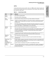
... the cooling fans have power cycled or reset the switch. The Status LED for more of the switch corresponding to the number, and the supply is NOT receiving power. A component of the switch has failed its self test. The normal operational state; The normal state; See chapter 4, "Troubleshooting" for the module or other device with the fault will flash simultaneously. The cooling fans are operating normally. Switch Chassis LEDs LEDs Power (green) Fault (orange...
... the cooling fans have power cycled or reset the switch. The Status LED for more of the switch corresponding to the number, and the supply is NOT receiving power. A component of the switch has failed its self test. The normal operational state; The normal state; See chapter 4, "Troubleshooting" for the module or other device with the fault will flash simultaneously. The cooling fans are operating normally. Switch Chassis LEDs LEDs Power (green) Fault (orange...

User Manual
Page 16
... ProCurve Switch 5300xl Series Front of the Switch Console Port This port is powered on. This connection is provided for at least one second, the Clear button deletes any configuration changes you may have occurred, executes the switch self test, and resets all network activity counters to the Switch" in a specific pattern, the Clear button clears any switch console access passwords that may have misplaced the password and need console access. It can be reset to restore the factory default configuration, see "Restoring the Factory Default Configuration" in a secure...
... ProCurve Switch 5300xl Series Front of the Switch Console Port This port is powered on. This connection is provided for at least one second, the Clear button deletes any configuration changes you may have occurred, executes the switch self test, and resets all network activity counters to the Switch" in a specific pattern, the Clear button clears any switch console access passwords that may have misplaced the password and need console access. It can be reset to restore the factory default configuration, see "Restoring the Factory Default Configuration" in a secure...

User Manual
Page 19
... console includes complete switch management through a command line interface (CLI) and a slightly reduced feature set accessible through several available interfaces: • web browser interface-an easy to the switch. Open Shortest Path First • DHCP relay ■ support for a description, see the Management and Configuration Guide that is used to manage your entire network, included with configurable address aging value. ■ full-duplex operation available on all ports are enabled-just connect the network cables to active network devices and your switched network...
... console includes complete switch management through a command line interface (CLI) and a slightly reduced feature set accessible through several available interfaces: • web browser interface-an easy to the switch. Open Shortest Path First • DHCP relay ■ support for a description, see the Management and Configuration Guide that is used to manage your entire network, included with configurable address aging value. ■ full-duplex operation available on all ports are enabled-just connect the network cables to active network devices and your switched network...
User Manual
Page 32
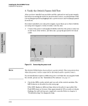
Installing the Switch 5300xl Series Note 2-12 connect power cord to a power source. If your installation requires a different power cord than approximately 120 seconds or it starts flashing, the self test has not completed correctly. Check the LEDs on the switch and on each of the switch, and then into a power source and verifying it works correctly also. 1. If the LED display is different than what is working properly by...
Installing the Switch 5300xl Series Note 2-12 connect power cord to a power source. If your installation requires a different power cord than approximately 120 seconds or it starts flashing, the self test has not completed correctly. Check the LEDs on the switch and on each of the switch, and then into a power source and verifying it works correctly also. 1. If the LED display is different than what is working properly by...
User Manual
Page 33
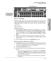
...; The port LEDs on the port. • If the ports are on the number and type of modules installed in sequence, as the modules receive power and code is downloaded to them, the Fault LED goes off, and the chassis LEDs go off except Power, Self Test, Fan Status, and Power Status. ■ When the download of the self test, the Self Test LED stays on. LED Mode Select switch module LEDs: Link and Mode LEDs for each power supply installed, and one for a fully loaded chassis, depending...
...; The port LEDs on the port. • If the ports are on the number and type of modules installed in sequence, as the modules receive power and code is downloaded to them, the Fault LED goes off, and the chassis LEDs go off except Power, Self Test, Fan Status, and Power Status. ■ When the download of the self test, the Self Test LED stays on. LED Mode Select switch module LEDs: Link and Mode LEDs for each power supply installed, and one for a fully loaded chassis, depending...

User Manual
Page 43
... number of Gigabit speeds through a configuration change on the Edge When your network expands and the users need to provide redundancy and load sharing for local connections, and the availability of network users. Use as a campus backbone or core switch. The connections are trunked, through either the Gigabit Transceiver xl Module or the 100/1000-T xl Module, the Switch 5300xl Series can serve as an Edge Switch trunked redundant Gigabit fiber-optic cables Installing the Switch 5300xl Series Example Network...
... number of Gigabit speeds through a configuration change on the Edge When your network expands and the users need to provide redundancy and load sharing for local connections, and the availability of network users. Use as a campus backbone or core switch. The connections are trunked, through either the Gigabit Transceiver xl Module or the 100/1000-T xl Module, the Switch 5300xl Series can serve as an Edge Switch trunked redundant Gigabit fiber-optic cables Installing the Switch 5300xl Series Example Network...

User Manual
Page 47
... Management and Configuration Guide. 3-1 Getting Started With Switch Configuration For a listing of switch features available with and without an IP address, refer to "IP Configuration" in the Switch Setup screen can configure them with your control of the network traffic, and to improve network security. For more information on using the console Switch Setup screen to quickly assign an IP (Internet Protocol) address and subnet mask to the switch, set a Manager password, and, optionally, configure other switch management interfaces: the web browser interface and the SNMP management...
... Management and Configuration Guide. 3-1 Getting Started With Switch Configuration For a listing of switch features available with and without an IP address, refer to "IP Configuration" in the Switch Setup screen can configure them with your control of the network traffic, and to improve network security. For more information on using the console Switch Setup screen to quickly assign an IP (Internet Protocol) address and subnet mask to the switch, set a Manager password, and, optionally, configure other switch management interfaces: the web browser interface and the SNMP management...

User Manual
Page 48
... display the Switch Setup screen. Use the Tab key to the switch, start a console session, and access the Switch Setup screen. 1. The CLI prompt appears displaying the switch model number: ProCurve Switch 5308xl 2. Using the method described in your network is configured to acquire an IP address configuration from a DHCP or Bootp server. The following illustration is on the ProCurve Web site, www.procurve.com. To use a direct console connection to select the Manager Password field and enter a manager password of a Setup screen with default settings.
... display the Switch Setup screen. Use the Tab key to the switch, start a console session, and access the Switch Setup screen. 1. The CLI prompt appears displaying the switch model number: ProCurve Switch 5308xl 2. Using the method described in your network is configured to acquire an IP address configuration from a DHCP or Bootp server. The following illustration is on the ProCurve Web site, www.procurve.com. To use a direct console connection to select the Manager Password field and enter a manager password of a Setup screen with default settings.

User Manual
Page 49
...; TimeP Mode Disabled Synchronizes the time kept on the fields in your network. 7. Note: The IP address and subnet mask assigned for console access. For more information on IP addressing, see the Management and Configuration Guide which is already running on the ProCurve Web site, www.procurve.com. The alternative is used for Save). IP Config DHCP/Bootp Set to Manual unless a DHCP/Bootp server is the Menu interface. Getting Started With Switch Configuration 4. Default Gateway blank Recommended...
...; TimeP Mode Disabled Synchronizes the time kept on the fields in your network. 7. Note: The IP address and subnet mask assigned for console access. For more information on IP addressing, see the Management and Configuration Guide which is already running on the ProCurve Web site, www.procurve.com. The alternative is used for Save). IP Config DHCP/Bootp Set to Manual unless a DHCP/Bootp server is the Menu interface. Getting Started With Switch Configuration 4. Default Gateway blank Recommended...

User Manual
Page 55
... of the new VLAN. To change the uplink VLAN from the CLI command prompt at the global configuration level ProCurve Switch 5308xl (config) # vlan assign the module's uplink to reboot the switch. For example, if the module is assigned to the rest of the network and the 740wl/760wl. Note Getting Started With Switch Configuration Configuring the ProCurve Access Controller xl Module (J8162A) 5300xl Switch Configuration Configuring the switch consists of assigning switch ports as client downlink ports and reviewing the uplink VLAN used as an...
... of the new VLAN. To change the uplink VLAN from the CLI command prompt at the global configuration level ProCurve Switch 5308xl (config) # vlan assign the module's uplink to reboot the switch. For example, if the module is assigned to the rest of the network and the 740wl/760wl. Note Getting Started With Switch Configuration Configuring the ProCurve Access Controller xl Module (J8162A) 5300xl Switch Configuration Configuring the switch consists of assigning switch ports as client downlink ports and reviewing the uplink VLAN used as an...
User Manual
Page 60
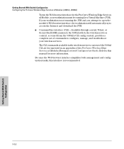
... to access the Internet and download the JVM. ■ Command line interface (CLI)-Available through a serial, Telnet, or Secure Shell (SSH) session to the 5300xl switch, the wireless services context, accessed from the 5300xl's CLI config context, provides a complete set of the ProCurve Wireless Edge Services xl Modules Management and Configuration Guide. Getting Started With Switch Configuration Configuring the ProCurve Wireless Edge Services xl Modules (J9001A, J9003A) To run the Web browser interface for more information. The CLI commands available in the wireless services context...
... to access the Internet and download the JVM. ■ Command line interface (CLI)-Available through a serial, Telnet, or Secure Shell (SSH) session to the 5300xl switch, the wireless services context, accessed from the 5300xl's CLI config context, provides a complete set of the ProCurve Wireless Edge Services xl Modules Management and Configuration Guide. Getting Started With Switch Configuration Configuring the ProCurve Wireless Edge Services xl Modules (J9001A, J9003A) To run the Web browser interface for more information. The CLI commands available in the wireless services context...
User Manual
Page 65
... your HP-authorized LAN dealer, or use the electronic support services from HP to get information on supported Switch xl modules. Call your HP-authorized LAN dealer, or use the electronic support services from HP to get a chance to the letter that is flashing is plugged into the outlet. See the Customer Support/Warranty card for more LEDs will fit in your ProCurve xl switch. Start a console session with the cover plate. If the problem is installed...
... your HP-authorized LAN dealer, or use the electronic support services from HP to get information on supported Switch xl modules. Call your HP-authorized LAN dealer, or use the electronic support services from HP to get a chance to the letter that is flashing is plugged into the outlet. See the Customer Support/Warranty card for more LEDs will fit in your ProCurve xl switch. Start a console session with the cover plate. If the problem is installed...

User Manual
Page 66
... Reset button. • power cycling the switch. • selecting the reset or reboot option from HP to get assistance. Call your Switch xl, as of the printing of the ones listed on ). The documentation that came with the module will not work properly until the switch is indicating the fault. The modules that are supported in your HP-authorized LAN dealer, or use the electronic support services from the console, web browser interface, or ProCurve Manager...
... Reset button. • power cycling the switch. • selecting the reset or reboot option from HP to get assistance. Call your Switch xl, as of the printing of the ones listed on ). The documentation that came with the module will not work properly until the switch is indicating the fault. The modules that are supported in your HP-authorized LAN dealer, or use the electronic support services from the console, web browser interface, or ProCurve Manager...

User Manual
Page 67
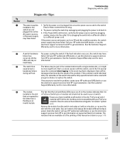
... During the module self test, described in tip number 4 earlier in the module Installation Guide. the flashing authorized LAN dealer, or use the electronic support services from HP to remove the module. Contact your HP- In the console, you can configure the switch so that whenever a for best operation, the switch should be replaced. Troubleshooting 4-7 In the mean time, all the other module ports will be identified with the LEDs Tip Number ➐ Problem The network port for more...
... During the module self test, described in tip number 4 earlier in the module Installation Guide. the flashing authorized LAN dealer, or use the electronic support services from HP to remove the module. Contact your HP- In the console, you can configure the switch so that whenever a for best operation, the switch should be replaced. Troubleshooting 4-7 In the mean time, all the other module ports will be identified with the LEDs Tip Number ➐ Problem The network port for more...

User Manual
Page 68
... other switches, and routers, use straight-through cable; Troubleshooting Diagnosing with the LEDs Tip Number l Problem The network connection is configured as "Auto", the port on the attached device also MUST be configured as MDI-X only and the correct type of cable must include all . For example, if the switch port is not working properly. Note: If the module configuration is connected to the ANSI/TIA/EIA568-A-5 specifications. Troubleshooting 4-8 See the "HP Auto-MDIX Feature" description on the port type...
... other switches, and routers, use straight-through cable; Troubleshooting Diagnosing with the LEDs Tip Number l Problem The network connection is configured as "Auto", the port on the attached device also MUST be configured as MDI-X only and the correct type of cable must include all . For example, if the switch port is not working properly. Note: If the module configuration is connected to the ANSI/TIA/EIA568-A-5 specifications. Troubleshooting 4-8 See the "HP Auto-MDIX Feature" description on the port type...
User Manual
Page 72
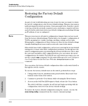
... in network connectivity issues. Using pointed objects, simultaneously press both the save the switch configuration prior to the factory default settings. As soon as the Self Test LED begins to press the Clear button while releasing the Reset button. 3. Continue to blink, release the Clear button. To restore the factory default configuration using the console, execute the erase startup config command from the factory default settings. This process removes all switch configuration changes that is configured. Then, after the reset and resolution of VLANs, spanning tree, trunks...
... in network connectivity issues. Using pointed objects, simultaneously press both the save the switch configuration prior to the factory default settings. As soon as the Self Test LED begins to press the Clear button while releasing the Reset button. 3. Continue to blink, release the Clear button. To restore the factory default configuration using the console, execute the erase startup config command from the factory default settings. This process removes all switch configuration changes that is configured. Then, after the reset and resolution of VLANs, spanning tree, trunks...

User Manual
Page 73
... network records network addresses assigned to use of a number of automated electronic services. HP Customer Support Services If you are still having trouble with services offered by HP. Please see the Management and Configuration Guide that is on the modules and mini-GBICs • details about the switch's status including the OS (software) version, a copy of the switch configuration, a copy of the switch Event Log, and a copy of the switch status and counters information switch console: show tech command...
... network records network addresses assigned to use of a number of automated electronic services. HP Customer Support Services If you are still having trouble with services offered by HP. Please see the Management and Configuration Guide that is on the modules and mini-GBICs • details about the switch's status including the OS (software) version, a copy of the switch configuration, a copy of the switch Event Log, and a copy of the switch status and counters information switch console: show tech command...

User Manual
Page 99
... types ... 2-6 serial for in-band console access ... 2-19 buttons Clear button ... 1-8 LED Mode Select button ... 1-7 Reset button ... 1-8 C cabinet mounting the switch in ... 2-14 note on mounting screws ... 2-16 cables 100/1000Base-T cable specifications ... B-2 twisted-pair cable specifications ... B-2 10Base-T cable specifications ... B-2 ports, cables used with ... B-4 B back of non-standard cables ... 4-1 fiber-optic, specifications ... B-2 connecting cables to switch ports ... 2-18 effects of switch description ... 1-9 power connector ... 1-9 slot for redundant power supply...
... types ... 2-6 serial for in-band console access ... 2-19 buttons Clear button ... 1-8 LED Mode Select button ... 1-7 Reset button ... 1-8 C cabinet mounting the switch in ... 2-14 note on mounting screws ... 2-16 cables 100/1000Base-T cable specifications ... B-2 twisted-pair cable specifications ... B-2 10Base-T cable specifications ... B-2 ports, cables used with ... B-4 B back of non-standard cables ... 4-1 fiber-optic, specifications ... B-2 connecting cables to switch ports ... 2-18 effects of switch description ... 1-9 power connector ... 1-9 slot for redundant power supply...


