
Installation Guide
Page 6
... Factory Default Configuration 3-10 HP Customer Support Services 3-11 Before Calling Support 3-11 iv Connect the Network Cables 2-14 Using the RJ-45 Connectors (10/100Base-TX ports 2-14 Connecting Cables to the Switch Module 2-14 7. (Optional) Connect a Console to the Switch 2-15 Terminal Configuration 2-15 Direct Console Access 2-16 Telnet Console Access 2-16 Sample Network Topologies 2-17 As a Desktop Switch 2-17 As a Segment Switch 2-18 Connecting to a Backbone Switch 2-19 Hot Swapping the Switch Module 2-20 Adding or Replacing the Module 2-20 Changing the Module Type...
... Factory Default Configuration 3-10 HP Customer Support Services 3-11 Before Calling Support 3-11 iv Connect the Network Cables 2-14 Using the RJ-45 Connectors (10/100Base-TX ports 2-14 Connecting Cables to the Switch Module 2-14 7. (Optional) Connect a Console to the Switch 2-15 Terminal Configuration 2-15 Direct Console Access 2-16 Telnet Console Access 2-16 Sample Network Topologies 2-17 As a Desktop Switch 2-17 As a Segment Switch 2-18 Connecting to a Backbone Switch 2-19 Hot Swapping the Switch Module 2-20 Adding or Replacing the Module 2-20 Changing the Module Type...

Installation Guide
Page 10
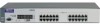
... HP ProCurve Switch 1600M and 2424M Front of the Switches Front of the Switches Reset and Clear buttons Self Test LED Slot for Switch Module (Switch 1600M) HP ProCurve Switch 1600M Power and Fault LEDs Console port Mode Select button and indicator LEDs Status LEDs for switch module, and fan Console port Link and Mode LEDs for Switch 2424M 10/100Base-TX ports Mode Select button and indicator LEDs 10/100Base-TX RJ-45 ports with Link and Mode LEDs at each port HP ProCurve Switch 2424M Self Test and Module Status LEDs Reset and Clear buttons 10/100Base-TX RJ-45 ports Network Ports...
... HP ProCurve Switch 1600M and 2424M Front of the Switches Front of the Switches Reset and Clear buttons Self Test LED Slot for Switch Module (Switch 1600M) HP ProCurve Switch 1600M Power and Fault LEDs Console port Mode Select button and indicator LEDs Status LEDs for switch module, and fan Console port Link and Mode LEDs for Switch 2424M 10/100Base-TX ports Mode Select button and indicator LEDs 10/100Base-TX RJ-45 ports with Link and Mode LEDs at each port HP ProCurve Switch 2424M Self Test and Module Status LEDs Reset and Clear buttons 10/100Base-TX RJ-45 ports Network Ports...

Installation Guide
Page 11
... fans have power cycled or reset the switch. the switch is flashing by itself, a different module type has been hot swapped into the switch; The switch Fault LED, and the Self Test LED may be flashing simultaneously. † The blinking behavior is on /off . If the Module Status LED is not undergoing self test. The Status LED for a prolonged time, the switch has encountered a fatal hardware failure, or has failed its self test. Fan Status (green) Switch 1600M only On Blinking...
... fans have power cycled or reset the switch. the switch is flashing by itself, a different module type has been hot swapped into the switch; The switch Fault LED, and the Self Test LED may be flashing simultaneously. † The blinking behavior is on /off . If the Module Status LED is not undergoing self test. The Status LED for a prolonged time, the switch has encountered a fatal hardware failure, or has failed its self test. Fan Status (green) Switch 1600M only On Blinking...

Installation Guide
Page 13
... the switch console, the web browser interface, and SNMP management, and restores the factory default configuration to the switch. When pressed by using the serial cable supplied with the security of the switch configuration and operation, you may have misplaced the password and need console access. Use this manual. 1-5 s Restoring Factory Default Configuration - This connection is powered on. For the specific method to the switch by itself for your convenience, but its presence means that may have configured. This action clears any configuration changes you...
... the switch console, the web browser interface, and SNMP management, and restores the factory default configuration to the switch. When pressed by using the serial cable supplied with the security of the switch configuration and operation, you may have misplaced the password and need console access. Use this manual. 1-5 s Restoring Factory Default Configuration - This connection is powered on. For the specific method to the switch by itself for your convenience, but its presence means that may have configured. This action clears any configuration changes you...

Installation Guide
Page 15
... be accessed from common web browsers. • console interface-a full featured, easy to use, VT-100 terminal interface that is especially good for out-of-band switch management, or for telnet access to the switch. • HP TopTools for Switch 2424M only, available Summer 1999) s the modules are "hot swappable" s plug-and-play networking-all ports are enabled-just connect the network cables to active network devices and your business needs s support for installing...
... be accessed from common web browsers. • console interface-a full featured, easy to use, VT-100 terminal interface that is especially good for out-of-band switch management, or for telnet access to the switch. • HP TopTools for Switch 2424M only, available Summer 1999) s the modules are "hot swappable" s plug-and-play networking-all ports are enabled-just connect the network cables to active network devices and your business needs s support for installing...

Installation Guide
Page 20
.... 2-2 Connect power to the switch ports. 7. Connect the network devices (page 2-14). Configuration changes can be installed and removed after the switch is properly prepared including having the correct network cabling ready to connect to install your network should be made easily by using a web browser, from an SNMP network management station, or through a telnet session to the switch's console port. Make sure that the physical environment into a power source and observing that the switch passes self test (page 2-8). Install switch module...
.... 2-2 Connect power to the switch ports. 7. Connect the network devices (page 2-14). Configuration changes can be installed and removed after the switch is properly prepared including having the correct network cabling ready to connect to install your network should be made easily by using a web browser, from an SNMP network management station, or through a telnet session to the switch's console port. Make sure that the physical environment into a power source and observing that the switch passes self test (page 2-8). Install switch module...

Installation Guide
Page 27
... network devices, the Link and Mode LEDs will stay off . • The port LEDs on the front of the self test, the Self Test LED stays on. Refer to chapter 3, "Troubleshooting" for more than 60 seconds or they start blinking, the self test has not completed correctly. Installing the Switch 1600M and 2424M Installation Procedures switch port LEDs Installing the Switch 1600M and 2424M Power and Fault LEDs Self Test LED When the switch is powered on and the Mode LEDs...
... network devices, the Link and Mode LEDs will stay off . • The port LEDs on the front of the self test, the Self Test LED stays on. Refer to chapter 3, "Troubleshooting" for more than 60 seconds or they start blinking, the self test has not completed correctly. Installing the Switch 1600M and 2424M Installation Procedures switch port LEDs Installing the Switch 1600M and 2424M Power and Fault LEDs Self Test LED When the switch is powered on and the Mode LEDs...

Installation Guide
Page 32
... ports on . If the Link LED does not go on when the network cable is connected to the port, see "Diagnosing With the LEDs" in general for connections to the port, see "Diagnosing With the LEDs" in the switch. See the documentation accompanying the modules for cabling configurations and procedures for that port should light to confirm a powered-on device (for example, an end node) is connected to the module, but, in chapter 3, "Troubleshooting". Using...
... ports on . If the Link LED does not go on when the network cable is connected to the port, see "Diagnosing With the LEDs" in general for connections to the port, see "Diagnosing With the LEDs" in the switch. See the documentation accompanying the modules for cabling configurations and procedures for that port should light to confirm a powered-on device (for example, an end node) is connected to the module, but, in chapter 3, "Troubleshooting". Using...

Installation Guide
Page 33
... PC or terminal has a 25-pin serial connector, you can be used as " parameter. s In-Band: Access the console using either one in troubleshooting s Download new software to the switch s Add passwords to control console, web browser interface, and network management access to the switch The console can use a readily available 9-pin to 25-pin serial cable, or attach a 9-to-25 pin adapter to the end of the supplied cable. Terminal Configuration To connect a console to the switch, configure the PC terminal emulator as a DEC...
... PC or terminal has a 25-pin serial connector, you can be used as " parameter. s In-Band: Access the console using either one in troubleshooting s Download new software to the switch s Add passwords to control console, web browser interface, and network management access to the switch The console can use a readily available 9-pin to 25-pin serial cable, or attach a 9-to-25 pin adapter to the end of the supplied cable. Terminal Configuration To connect a console to the switch, configure the PC terminal emulator as a DEC...

Installation Guide
Page 34
... using a Ping command to the switch's IP address). 2. Turn on the terminal or PC's power and, if using the console cable included with the switch. (If your PC or terminal has a 25-pin serial connector, first console cable supplied with the switch attach a 9-pin to 25-pin adapter at one end of the switch at this time, refer to the Management and Configuration Guide that the switch is configured with an IP address and that came with console management of the console cable.) 2. Telnet Console Access...
... using a Ping command to the switch's IP address). 2. Turn on the terminal or PC's power and, if using the console cable included with the switch. (If your PC or terminal has a 25-pin serial connector, first console cable supplied with the switch attach a 9-pin to 25-pin adapter at one end of the switch at this time, refer to the Management and Configuration Guide that the switch is configured with an IP address and that came with console management of the console cable.) 2. Telnet Console Access...

Installation Guide
Page 42
... have network problems after recent changes to the network, change back to these MDI ports, use a crossover cable. Most switch and hub ports are wired as are using twistedpair cable from the switch to the previous topology. A category 5 cable tester is probably at the HP World Wide Web site for these items first when starting your switch to an MDI-X connector on your troubleshooting: s Incorrect switch-to-switch or switch-to -hub connections use...
... have network problems after recent changes to the network, change back to these MDI ports, use a crossover cable. Most switch and hub ports are wired as are using twistedpair cable from the switch to the previous topology. A category 5 cable tester is probably at the HP World Wide Web site for these items first when starting your switch to an MDI-X connector on your troubleshooting: s Incorrect switch-to-switch or switch-to -hub connections use...

Installation Guide
Page 45
... switch and replace it is hot swapped (installed when the switch is powered on until the error is resolved. • The switch software, including console and web browser access will not be retested automatically. Call your HP-authorized LAN dealer, or use the electronic support services from HP to get assistance. Call your HP-authorized LAN dealer, or use the electronic support services from the time the module gets into the outlet. See the Customer Support/Warranty card...
... switch and replace it is hot swapped (installed when the switch is powered on until the error is resolved. • The switch software, including console and web browser access will not be retested automatically. Call your HP-authorized LAN dealer, or use the electronic support services from HP to get assistance. Call your HP-authorized LAN dealer, or use the electronic support services from the time the module gets into the outlet. See the Customer Support/Warranty card...

Installation Guide
Page 46
... 8, "Troubleshooting" in the Management and Configuration Guide that this condition if the ambient temperature does not exceed normal room (Switch 1600M temperature, but for fiber-optic connections, verify that the port has not been disabled through " cable; The module will than the one or cooling fans may have configured an IP address on the switch, use the web browser interface, or HP TopTools for these methods: • pressing the Reset button...
... 8, "Troubleshooting" in the Management and Configuration Guide that this condition if the ambient temperature does not exceed normal room (Switch 1600M temperature, but for fiber-optic connections, verify that the port has not been disabled through " cable; The module will than the one or cooling fans may have configured an IP address on the switch, use the web browser interface, or HP TopTools for these methods: • pressing the Reset button...

Installation Guide
Page 48
... the console screen when the switch is installed in the power cord (power cycling) s Press the reset button on the front of the switch Power cycling the switch and pressing the Reset button both cause the switch to perform its circuitry and operating code. Checking the Switch LEDs The selftest passes if the Fault and Self Test LEDs on the front of the reset procedures cause any network traffic counters to test its power...
... the console screen when the switch is installed in the power cord (power cycling) s Press the reset button on the front of the switch Power cycling the switch and pressing the Reset button both cause the switch to perform its circuitry and operating code. Checking the Switch LEDs The selftest passes if the Fault and Self Test LEDs on the front of the reset procedures cause any network traffic counters to test its power...

Installation Guide
Page 50
... blink, release the Clear button. To execute the factory default reset, perform these steps: 1. Troubleshooting Restoring the Factory Default Configuration Testing End-to-End Network Communications Both the switch and the cabling can be tested by running a link test or Ping test. When the Self Test LED begins to -end communications test -- For example, if you can run a link-level test or Ping test through the switch. Continue to the factory default settings. This process momentarily interrupts the switch operation, clears any passwords, clears the console event log, resets...
... blink, release the Clear button. To execute the factory default reset, perform these steps: 1. Troubleshooting Restoring the Factory Default Configuration Testing End-to-End Network Communications Both the switch and the cabling can be tested by running a link test or Ping test. When the Self Test LED begins to -end communications test -- For example, if you can run a link-level test or Ping test through the switch. Continue to the factory default settings. This process momentarily interrupts the switch operation, clears any passwords, clears the console event log, resets...

Installation Guide
Page 51
... front of the switch: Switch 1600M (HP J4120A) or Switch 2424M (HP J4093A) • switch's OS (software) version switch console: Main Menu -> 1. The HP networking products World Wide Web site, http://www.hp.com/go/procurve also provides up-to-date support information. Browse Configuration File • copy of the switch status and counters information, including the detailed counters for information on how to use of a number of automated electronic services. Status and Counters -> 4. See...
... front of the switch: Switch 1600M (HP J4120A) or Switch 2424M (HP J4093A) • switch's OS (software) version switch console: Main Menu -> 1. The HP networking products World Wide Web site, http://www.hp.com/go/procurve also provides up-to-date support information. Browse Configuration File • copy of the switch status and counters information, including the detailed counters for information on how to use of a number of automated electronic services. Status and Counters -> 4. See...

Installation Guide
Page 72
...-over cable pin-out ... B-2 filtering out traffic ... 1-8 flashing LEDs error indications ... 3-4 flooding traffic ... 1-8 forwarding traffic ... 1-8 front of switch 10/100Base-TX ports ... 1-2 Clear button ... 1-5 console port ... 1-5 description ... 1-2 LEDs ... 1-3 Mode Select button and LEDs ... 1-4 network ports ... 1-2 Reset button ... 1-5 slot for in -band ... 2-15 how to connect out-of switch ... 1-2 LEDs ... 1-3 switch ... 1-1 desktop switch sample topology ... 2-17 DHCP for switch modules ... 1-2 G Gigabit-LX connections, length limitations ... 2-4 ports, cables used with...
...-over cable pin-out ... B-2 filtering out traffic ... 1-8 flashing LEDs error indications ... 3-4 flooding traffic ... 1-8 forwarding traffic ... 1-8 front of switch 10/100Base-TX ports ... 1-2 Clear button ... 1-5 console port ... 1-5 description ... 1-2 LEDs ... 1-3 Mode Select button and LEDs ... 1-4 network ports ... 1-2 Reset button ... 1-5 slot for in -band ... 2-15 how to connect out-of switch ... 1-2 LEDs ... 1-3 switch ... 1-1 desktop switch sample topology ... 2-17 DHCP for switch modules ... 1-2 G Gigabit-LX connections, length limitations ... 2-4 ports, cables used with...

Installation Guide
Page 73
...20 installing ... 2-6 LEDs ... 1-4 mounting the switch in -band console access types of ... 2-15 included parts ... 2-1 incorrect network connections ... 3-2 installation connecting the switch to a power source ... 2-13 horizontal surface mounting ... 2-12 network cable requirements ... 2-4 optional modules ... 2-6 precautions ... 2-3 rack or cabinet mounting ... 2-10 site preparation ... 2-4 summary of steps ... 2-2 Switch 1600M and 2400M ... 2-1 wall mounting ... 2-13 L LEDs 10/100Base-TX ports ... 1-4 100 ... 1-3 Act ... 1-3 behavior during self test ... 2-9 checking during troubleshooting...
...20 installing ... 2-6 LEDs ... 1-4 mounting the switch in -band console access types of ... 2-15 included parts ... 2-1 incorrect network connections ... 3-2 installation connecting the switch to a power source ... 2-13 horizontal surface mounting ... 2-12 network cable requirements ... 2-4 optional modules ... 2-6 precautions ... 2-3 rack or cabinet mounting ... 2-10 site preparation ... 2-4 summary of steps ... 2-2 Switch 1600M and 2400M ... 2-1 wall mounting ... 2-13 L LEDs 10/100Base-TX ports ... 1-4 100 ... 1-3 Act ... 1-3 behavior during self test ... 2-9 checking during troubleshooting...

Installation Guide
Page 74
... 2-15 network connections ... 2-14 power connector ... 1-6 Power LED ... 1-3 behavior during self test ... 2-9 serial cable for direct console connection ... 2-16 slot for module hot swap ... 2-20 location of -band console access ... 2-16 P parts, included with ... 3-7 R rack mounting precautions ... 2-3 mounting the switch in ... 2-10 rebooting the switch to initialize new module type ... 2-6 regulatory statements ... Index power source connecting the switch to ... 2-14 LEDs for ... 1-4 location on switch ... 1-2, 1-5 restoring factory default configuration ... 3-10 resetting the switch...
... 2-15 network connections ... 2-14 power connector ... 1-6 Power LED ... 1-3 behavior during self test ... 2-9 serial cable for direct console connection ... 2-16 slot for module hot swap ... 2-20 location of -band console access ... 2-16 P parts, included with ... 3-7 R rack mounting precautions ... 2-3 mounting the switch in ... 2-10 rebooting the switch to initialize new module type ... 2-6 regulatory statements ... Index power source connecting the switch to ... 2-14 LEDs for ... 1-4 location on switch ... 1-2, 1-5 restoring factory default configuration ... 3-10 resetting the switch...

Installation Guide
Page 75
... 3-2 link test ... 3-9 Ping test ... 3-9 Proactive Network tools ... 3-7 restoring factory default configuration ... 3-10 testing connections to other devices ... 3-9 testing end-to-end communications ... 3-10 testing the switch ... 3-8 testing the twisted-pair cables ... 3-9 twisted-pair cable cross-over cable pin-out ... A-1 switch modules booting the switch to a power source ... 2-13 description ... 1-1 electrical specifications ... B-5 testing ... 3-9 twisted-pair cables ... A-2 electrical ... A-1 features ... 1-7 front panel description ... 1-2 included parts ... 2-1 LED descriptions...
... 3-2 link test ... 3-9 Ping test ... 3-9 Proactive Network tools ... 3-7 restoring factory default configuration ... 3-10 testing connections to other devices ... 3-9 testing end-to-end communications ... 3-10 testing the switch ... 3-8 testing the twisted-pair cables ... 3-9 twisted-pair cable cross-over cable pin-out ... A-1 switch modules booting the switch to a power source ... 2-13 description ... 1-1 electrical specifications ... B-5 testing ... 3-9 twisted-pair cables ... A-2 electrical ... A-1 features ... 1-7 front panel description ... 1-2 included parts ... 2-1 LED descriptions...


