HP G72 Notebook PC - Maintenance and Service Guide
Page 8
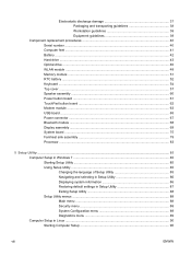
Electrostatic discharge damage 37 Packaging and transporting guidelines 38 Workstation guidelines 38 Equipment guidelines 39 Component replacement procedures 40 Serial number ...40 Computer feet ...41 Battery ...42 Hard drive ...43 Optical drive ...46 WLAN module ...48 Memory module ...51 RTC battery ...52 Keyboard ...54 Top cover ...57 Speaker assembly ...60 Power button board ...61 TouchPad...
Electrostatic discharge damage 37 Packaging and transporting guidelines 38 Workstation guidelines 38 Equipment guidelines 39 Component replacement procedures 40 Serial number ...40 Computer feet ...41 Battery ...42 Hard drive ...43 Optical drive ...46 WLAN module ...48 Memory module ...51 RTC battery ...52 Keyboard ...54 Top cover ...57 Speaker assembly ...60 Power button board ...61 TouchPad...
HP G72 Notebook PC - Maintenance and Service Guide
Page 14
...: Windows® 7 Home Premium (32 & 64 bit) Windows 7 Home Basic (32 & 64 bit) Free DOS End-user replaceable parts: AC adapter Battery (system) Hard drive Memory module Optical drive Mini-card devices HP G72 Discrete √ √ √ √ √ HP G72 UMA √ √ √ √ √ √ √ √ √ √ √ √ √ √ √...
...: Windows® 7 Home Premium (32 & 64 bit) Windows 7 Home Basic (32 & 64 bit) Free DOS End-user replaceable parts: AC adapter Battery (system) Hard drive Memory module Optical drive Mini-card devices HP G72 Discrete √ √ √ √ √ HP G72 UMA √ √ √ √ √ √ √ √ √ √ √ √ √ √ √...
HP G72 Notebook PC - Maintenance and Service Guide
Page 23
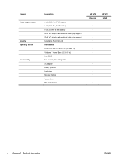
... computer functionality, and then contact technical support through Help and Support. If you replace the module and then receive a warning message, remove the module to cycle on select models, the wireless LAN (WLAN) device. Bottom components Component (1) (2) Battery bay Vents (5) (3) Battery release latch (4) Hard drive bay (5) Memory module compartment Description Holds the battery.
... computer functionality, and then contact technical support through Help and Support. If you replace the module and then receive a warning message, remove the module to cycle on select models, the wireless LAN (WLAN) device. Bottom components Component (1) (2) Battery bay Vents (5) (3) Battery release latch (4) Hard drive bay (5) Memory module compartment Description Holds the battery.
HP G72 Notebook PC - Maintenance and Service Guide
Page 32
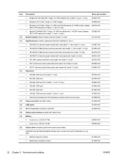
...BT3.0+HS ready) (for models 1.1 and 1.2 only) 602992-001 Modem module (select models only) (for model 1.0 only) 510100-001 System board (includes replacement thermal material) for use in: ● HD 5430/1 G discrete system board with card reader 1.1 (for model 1.1 only) 615847-001 ● HD 5430...001 ● 250 GB, 7200 rpm 615083-001 ● 160 GB, 7200 rpm (for models 1.0 and 1.1 only 615082-001 ● Hard Drive Hardware Kit (not illustrated, includes bracket and screws) 615086-001 Power connector (includes cable) 616496-001 USB board 616494-001 RJ-11 connector included...
...BT3.0+HS ready) (for models 1.1 and 1.2 only) 602992-001 Modem module (select models only) (for model 1.0 only) 510100-001 System board (includes replacement thermal material) for use in: ● HD 5430/1 G discrete system board with card reader 1.1 (for model 1.1 only) 615847-001 ● HD 5430...001 ● 250 GB, 7200 rpm 615083-001 ● 160 GB, 7200 rpm (for models 1.0 and 1.1 only 615082-001 ● Hard Drive Hardware Kit (not illustrated, includes bracket and screws) 615086-001 Power connector (includes cable) 616496-001 USB board 616494-001 RJ-11 connector included...

HP G72 Notebook PC - Maintenance and Service Guide
Page 42
...614549-001 615082-001 615083-001 615084-001 615085-001 615086-001 615847-001 615848-001 615850-001 Description Fan/heat sink assembly (includes replacement thermal material) for use with discrete systems 65-W AC adapter 90-W AC adapter 43.9-cm (17.3-in) HD, light-emitting diode ...DVD±RW and CD-RW SuperMulti Double-Layer Combo Drive with LightScribe for use with biscotti computer models 160 GB, 7200 rpm hard drive (for models 1.0 and 1.1 only) 250 GB, 7200 rpm hard drive 320 GB, 7200 rpm hard drive 500 GB, 7200 rpm hard drive Hard Drive Hardware Kit (includes bracket and screws) HD 5430/1 G...
...614549-001 615082-001 615083-001 615084-001 615085-001 615086-001 615847-001 615848-001 615850-001 Description Fan/heat sink assembly (includes replacement thermal material) for use with discrete systems 65-W AC adapter 90-W AC adapter 43.9-cm (17.3-in) HD, light-emitting diode ...DVD±RW and CD-RW SuperMulti Double-Layer Combo Drive with LightScribe for use with biscotti computer models 160 GB, 7200 rpm hard drive (for models 1.0 and 1.1 only) 250 GB, 7200 rpm hard drive 320 GB, 7200 rpm hard drive 500 GB, 7200 rpm hard drive Hard Drive Hardware Kit (includes bracket and screws) HD 5430/1 G...
HP G72 Notebook PC - Maintenance and Service Guide
Page 46
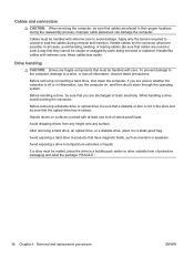
... flex cables with care. After removing a hard drive, an optical drive, or a diskette drive, place it down the computer. In all cases, avoid bending, twisting, or tearing cables. Handle drives on , and then shut it in the drive and be sure that you are routed in...foam. these precautions: Before removing or inserting a hard drive, shut down through the operating system. Improper cable placement can damage the computer. Handle cables by parts being removed or replaced. Before removing a diskette drive or optical drive, be sure that cables are unsure whether the ...
... flex cables with care. After removing a hard drive, an optical drive, or a diskette drive, place it down the computer. In all cases, avoid bending, twisting, or tearing cables. Handle drives on , and then shut it in the drive and be sure that you are routed in...foam. these precautions: Before removing or inserting a hard drive, shut down through the operating system. Improper cable placement can damage the computer. Handle cables by parts being removed or replaced. Before removing a diskette drive or optical drive, be sure that cables are unsure whether the ...

HP G72 Notebook PC - Maintenance and Service Guide
Page 53
...603787-001 603785-001 615085-001 622643-001 615084-001 615083-001 615082-001 615086-001 Before removing the hard drive: 1. ENWW Component replacement procedures 43 Position the computer with the front toward you are also available in Hibernation, turn on page 42...down the computer. Loosen the two Phillips PM2.5×6.0 captive screws (1) that secure the hard drive cover to the computer. 3. Hard drive NOTE: The hard drive spare part kit includes a hard drive bracket and hard drive connector. Remove the hard drive: 1. Disconnect all external devices connected to the computer.
...603787-001 603785-001 615085-001 622643-001 615084-001 615083-001 615082-001 615086-001 Before removing the hard drive: 1. ENWW Component replacement procedures 43 Position the computer with the front toward you are also available in Hibernation, turn on page 42...down the computer. Loosen the two Phillips PM2.5×6.0 captive screws (1) that secure the hard drive cover to the computer. 3. Hard drive NOTE: The hard drive spare part kit includes a hard drive bracket and hard drive connector. Remove the hard drive: 1. Disconnect all external devices connected to the computer.
HP G72 Notebook PC - Maintenance and Service Guide
Page 54
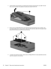
... (3) and lift the hard drive out (4) of the hard drive cover (2), swing it forward, and remove the cover (3). Remove the four Phillils PM2.5x5.0 screws (1) that secure the hard drive bracket to the computer. To replace the hard drive bracket, remove the four Phillips PM3.0×4.0 screws (1) that secure the hard drive to the hard drive 44 Chapter 4 Removal and replacement procedures ENWW Use...
... (3) and lift the hard drive out (4) of the hard drive cover (2), swing it forward, and remove the cover (3). Remove the four Phillils PM2.5x5.0 screws (1) that secure the hard drive bracket to the computer. To replace the hard drive bracket, remove the four Phillips PM3.0×4.0 screws (1) that secure the hard drive to the hard drive 44 Chapter 4 Removal and replacement procedures ENWW Use...
HP G72 Notebook PC - Maintenance and Service Guide
Page 55
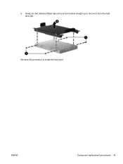
ENWW Component replacement procedures 45 6. Grasp the two attached Mylar tabs and pull the bracket straight up to install the hard drive. Reverse this procedure to remove it from the hard drive (2).
ENWW Component replacement procedures 45 6. Grasp the two attached Mylar tabs and pull the bracket straight up to install the hard drive. Reverse this procedure to remove it from the hard drive (2).
HP G72 Notebook PC - Maintenance and Service Guide
Page 56
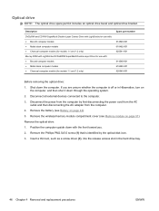
...Remove the battery (see Memory module on page 42). 5. Remove the optical drive: 1. If you . 2. Remove the Phillips PM2.5x5.0 screw (1) that is off or in the hard drive bay. 46 Chapter 4 Removal and replacement procedures ENWW Position the computer upside down the computer. Disconnect all external devices connected... ● Charcoal computer models (for models 1.1 and 1.2 only) Blu-ray ROM with LightScribe DVD±R/RW SuperMulti Double-Layer Drive for use with the front toward you are unsure whether the computer is identified by first disconnecting the power cord from the AC ...
...Remove the battery (see Memory module on page 42). 5. Remove the optical drive: 1. If you . 2. Remove the Phillips PM2.5x5.0 screw (1) that is off or in the hard drive bay. 46 Chapter 4 Removal and replacement procedures ENWW Position the computer upside down the computer. Disconnect all external devices connected... ● Charcoal computer models (for models 1.1 and 1.2 only) Blu-ray ROM with LightScribe DVD±R/RW SuperMulti Double-Layer Drive for use with the front toward you are unsure whether the computer is identified by first disconnecting the power cord from the AC ...
HP G72 Notebook PC - Maintenance and Service Guide
Page 64
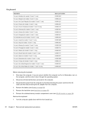
... wireless/memory module compartment cover (see WLAN module on page 42). 5. Remove the battery (see Hard drive on the computer, and then shut it down the computer. If you . 54 Chapter 4 Removal and replacement procedures ENWW Remove the hard drive (see Battery on page 48). Shut down through the operating system. 2. Keyboard Description For use...
... wireless/memory module compartment cover (see WLAN module on page 42). 5. Remove the battery (see Hard drive on the computer, and then shut it down the computer. If you . 54 Chapter 4 Removal and replacement procedures ENWW Remove the hard drive (see Battery on page 48). Shut down through the operating system. 2. Keyboard Description For use...
HP G72 Notebook PC - Maintenance and Service Guide
Page 67
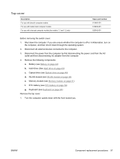
...page 54) Remove the top cover: 1. If you . WLAN module (see Keyboard on page 48) e. Shut down through the operating system. 2. ENWW Component replacement procedures 57 Top cover Description For use with biscotti computer models For use with matte black computer models For use with the front toward you... Memory module on page 46) d. Battery (see RTC battery on the computer, and then shut it down the computer. Hard drive (See Hard drive on page 42) b. Turn the computer upside down with charcoal computer models (for models 1.1 and 1.2 only) Spare part number 616490-001 616492-001...
...page 54) Remove the top cover: 1. If you . WLAN module (see Keyboard on page 48) e. Shut down through the operating system. 2. ENWW Component replacement procedures 57 Top cover Description For use with biscotti computer models For use with matte black computer models For use with the front toward you... Memory module on page 46) d. Battery (see RTC battery on the computer, and then shut it down the computer. Hard drive (See Hard drive on page 42) b. Turn the computer upside down with charcoal computer models (for models 1.1 and 1.2 only) Spare part number 616490-001 616492-001...
HP G72 Notebook PC - Maintenance and Service Guide
Page 70
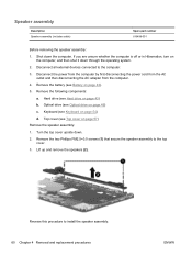
...on page 43) b. Keyboard (see Hard drive on page 54) d. Remove the two Phillips PM2.5×3.0 screws (1) that secure the speaker assembly to install the speaker assembly. 60 Chapter 4 Removal and replacement procedures ENWW Remove the battery (see Optical drive on page 42). 5. Turn the ... Description Speaker assembly (includes cable) Spare part number 616498-001 Before removing the speaker assembly: 1. Remove the following components: a. Optical drive (see Battery on page 46) c. If you are unsure whether the computer is off or in Hibernation, turn on page 57) ...
...on page 43) b. Keyboard (see Hard drive on page 54) d. Remove the two Phillips PM2.5×3.0 screws (1) that secure the speaker assembly to install the speaker assembly. 60 Chapter 4 Removal and replacement procedures ENWW Remove the battery (see Optical drive on page 42). 5. Turn the ... Description Speaker assembly (includes cable) Spare part number 616498-001 Before removing the speaker assembly: 1. Remove the following components: a. Optical drive (see Battery on page 46) c. If you are unsure whether the computer is off or in Hibernation, turn on page 57) ...
HP G72 Notebook PC - Maintenance and Service Guide
Page 71
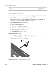
Disconnect all external devices connected to the top cover. 3. Hard drive (see Optical drive on , and then shut it down the computer. Remove the Phillips PM2.0×3.0 screw (1) that secures the power button board to the computer. ...c. Optical drive (see Hard drive on page 54) d. Shut down through the operating system. 2. Lift up and remove the power button board (2). Disconnect the power from the computer by first disconnecting the power cord from the AC outlet and then disconnecting the AC adapter from the computer. 4. ENWW Component replacement procedures 61...
Disconnect all external devices connected to the top cover. 3. Hard drive (see Optical drive on , and then shut it down the computer. Remove the Phillips PM2.0×3.0 screw (1) that secures the power button board to the computer. ...c. Optical drive (see Hard drive on page 54) d. Shut down through the operating system. 2. Lift up and remove the power button board (2). Disconnect the power from the computer by first disconnecting the power cord from the AC outlet and then disconnecting the AC adapter from the computer. 4. ENWW Component replacement procedures 61...

HP G72 Notebook PC - Maintenance and Service Guide
Page 72
... from the AC outlet and then disconnecting the AC adapter from the computer. 4. Optical drive (see Optical drive on page 57) Remove the TouchPad button board: 1. Top cover (see Hard drive on the TouchPad button board bracket. Turn the top cover upside down through the operating ...front toward you. 2. Hard drive (see Top cover on page 46) c. Reverse the above procedure to the computer. 3. Shut down the computer. Disconnect all external devices connected to reassemble and install the TouchPad button board. 62 Chapter 4 Removal and replacement procedures ENWW Remove the battery...
... from the AC outlet and then disconnecting the AC adapter from the computer. 4. Optical drive (see Optical drive on page 57) Remove the TouchPad button board: 1. Top cover (see Hard drive on the TouchPad button board bracket. Turn the top cover upside down through the operating ...front toward you. 2. Hard drive (see Top cover on page 46) c. Reverse the above procedure to the computer. 3. Shut down the computer. Disconnect all external devices connected to reassemble and install the TouchPad button board. 62 Chapter 4 Removal and replacement procedures ENWW Remove the battery...
HP G72 Notebook PC - Maintenance and Service Guide
Page 73
...first disconnecting the power cord from the AC outlet and then disconnecting the AC adapter from the system board. ENWW Component replacement procedures 63 If you . 2. Hard drive (see Top cover on page 42). 5. Turn the computer upright with the front toward you are unsure whether the ...computer is off or in Hibernation, turn on the computer, and then shut it from the computer. 4. Keyboard (see Optical drive on the front of...
...first disconnecting the power cord from the AC outlet and then disconnecting the AC adapter from the system board. ENWW Component replacement procedures 63 If you . 2. Hard drive (see Top cover on page 42). 5. Turn the computer upright with the front toward you are unsure whether the ...computer is off or in Hibernation, turn on the computer, and then shut it from the computer. 4. Keyboard (see Optical drive on the front of...
HP G72 Notebook PC - Maintenance and Service Guide
Page 75
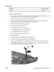
... the power from the computer by first disconnecting the power cord from the AC outlet and then disconnecting the AC adapter from the system board. 3. Hard drive (see Top cover on page 43) b. Lift the USB board (3) straight up to remove it down the computer. Remove the following components: a. Top cover (see... 616494-001 Before removing the USB board: 1. If you . 2. Position the computer upright with the cable kit using spare part number 616502-001 ENWW Component replacement procedures 65 Disconnect the USB board cable (1) from the computer. 4.
... the power from the computer by first disconnecting the power cord from the AC outlet and then disconnecting the AC adapter from the system board. 3. Hard drive (see Top cover on page 43) b. Lift the USB board (3) straight up to remove it down the computer. Remove the following components: a. Top cover (see... 616494-001 Before removing the USB board: 1. If you . 2. Position the computer upright with the cable kit using spare part number 616502-001 ENWW Component replacement procedures 65 Disconnect the USB board cable (1) from the computer. 4.
HP G72 Notebook PC - Maintenance and Service Guide
Page 77
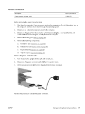
... toward you are unsure whether the computer is off or in Hibernation, turn on page 46) c. ENWW Component replacement procedures 67 Optical drive (see Optical drive on the computer, and then shut it down the computer. Keyboard (see Top cover on page 54) d. ...Spare part number 616496-001 Before removing the power connector cable: 1. Remove the following components: a. Remove the battery (see Hard drive on page 42). 5. Hard drive (see Battery on page 43) b. Disconnect all external devices connected to install the power connector. Shut down through the operating system....
... toward you are unsure whether the computer is off or in Hibernation, turn on page 46) c. ENWW Component replacement procedures 67 Optical drive (see Optical drive on the computer, and then shut it down the computer. Keyboard (see Top cover on page 54) d. ...Spare part number 616496-001 Before removing the power connector cable: 1. Remove the following components: a. Remove the battery (see Hard drive on page 42). 5. Hard drive (see Battery on page 43) b. Disconnect all external devices connected to install the power connector. Shut down through the operating system....
HP G72 Notebook PC - Maintenance and Service Guide
Page 78
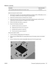
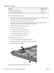
Disconnect all external devices connected to install the Bluetooth module. 68 Chapter 4 Removal and replacement procedures ENWW Remove the following components: a. Keyboard (see Battery on page 54) d. If you . 2. Disconnect the ... module cable (1) from the computer. 4. Remove the battery (see Keyboard on page 42). 5. Hard drive (see Optical drive on page 43) b. Remove the Bluetooth module (2). Reverse this procedure to the computer. 3. Optical drive (see Hard drive on page 46) c. Bluetooth module Description Bluetooth module (for model 1.0 only) Bluetooth module cable ...
Disconnect all external devices connected to install the Bluetooth module. 68 Chapter 4 Removal and replacement procedures ENWW Remove the following components: a. Keyboard (see Battery on page 54) d. If you . 2. Disconnect the ... module cable (1) from the computer. 4. Remove the battery (see Keyboard on page 42). 5. Hard drive (see Optical drive on page 43) b. Remove the Bluetooth module (2). Reverse this procedure to the computer. 3. Optical drive (see Hard drive on page 46) c. Bluetooth module Description Bluetooth module (for model 1.0 only) Bluetooth module cable ...
HP G72 Notebook PC - Maintenance and Service Guide
Page 79
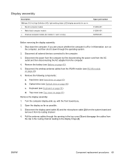
... in the routing channel leading to the computer. 3. Open the display as far as possible. 3. Pull the antenna cables through the operating system. 2. ENWW Component replacement procedures 69 Display assembly Description 39.6-cm (15.6-in) High Definition (HD), light-emitting diode (LED) display assembly for use in the top cover (3) and... power from the computer by first disconnecting the power cord from the AC outlet and then disconnecting the AC adapter from the WLAN module (see Hard drive on page 43) b. Disconnect the wireless antenna cables from the computer...
... in the routing channel leading to the computer. 3. Open the display as far as possible. 3. Pull the antenna cables through the operating system. 2. ENWW Component replacement procedures 69 Display assembly Description 39.6-cm (15.6-in) High Definition (HD), light-emitting diode (LED) display assembly for use in the top cover (3) and... power from the computer by first disconnecting the power cord from the AC outlet and then disconnecting the AC adapter from the WLAN module (see Hard drive on page 43) b. Disconnect the wireless antenna cables from the computer...


