Notebook PC User Guide - Windows 7
Page 7
... adapter 51 Testing an AC adapter ...52 Using battery power ...53 Finding battery information in Help and Support 53 Using Battery Check ...53 Displaying the remaining battery charge 54 Inserting or removing the battery 54 Charging a battery ...55 Maximizing battery discharge time 56 Managing low battery levels ...Fully recharge the battery 59 Step 5: Reenable Hibernation and Sleep 60 Conserving battery power 60 Storing a battery ...60 Disposing of a used battery 61 Replacing the battery ...61 Switching between graphics modes (select models only 62 Shutting down the computer ...63 vii
... adapter 51 Testing an AC adapter ...52 Using battery power ...53 Finding battery information in Help and Support 53 Using Battery Check ...53 Displaying the remaining battery charge 54 Inserting or removing the battery 54 Charging a battery ...55 Maximizing battery discharge time 56 Managing low battery levels ...Fully recharge the battery 59 Step 5: Reenable Hibernation and Sleep 60 Conserving battery power 60 Storing a battery ...60 Disposing of a used battery 61 Replacing the battery ...61 Switching between graphics modes (select models only 62 Shutting down the computer ...63 vii
Notebook PC User Guide - Windows 7
Page 8
..., or it stops before completion 75 A DVD playing in Windows Media Player produces no sound or display 75 A device driver must be reinstalled 75 Obtaining the latest HP device drivers 76 Obtaining the latest Windows device drivers 77 Using external drives ...78 Improving hard drive ...performance ...79 Using Disk Defragmenter 79 Using Disk Cleanup ...79 Replacing the hard drive ...80 7 External devices and external...
..., or it stops before completion 75 A DVD playing in Windows Media Player produces no sound or display 75 A device driver must be reinstalled 75 Obtaining the latest HP device drivers 76 Obtaining the latest Windows device drivers 77 Using external drives ...78 Improving hard drive ...performance ...79 Using Disk Defragmenter 79 Using Disk Cleanup ...79 Replacing the hard drive ...80 7 External devices and external...

Notebook PC User Guide - Windows 7
Page 9
8 Adding or replacing a memory module 9 Security Protecting the computer ...91 Using passwords ...92 Setting passwords in Windows 92 Setting passwords in Setup Utility 92 Administrator password 93 Managing ... A Setup Utility (BIOS) Starting Setup Utility ...97 Using Setup Utility ...98 Changing the language of Setup Utility 98 Navigating and selecting in Setup Utility 98 Displaying system information 99 Restoring default settings in Setup Utility 99 Exiting Setup Utility ...100 Setup Utility menus ...100 Main menu ...100 Security menu ...100 System...
8 Adding or replacing a memory module 9 Security Protecting the computer ...91 Using passwords ...92 Setting passwords in Windows 92 Setting passwords in Setup Utility 92 Administrator password 93 Managing ... A Setup Utility (BIOS) Starting Setup Utility ...97 Using Setup Utility ...98 Changing the language of Setup Utility 98 Navigating and selecting in Setup Utility 98 Displaying system information 99 Restoring default settings in Setup Utility 99 Exiting Setup Utility ...100 Setup Utility menus ...100 Main menu ...100 Security menu ...100 System...
Notebook PC User Guide - Windows 7
Page 60
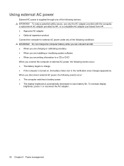
...or DVD When you disconnect external AC power, the following events occur: ● The computer switches to battery power. ● The display brightness is automatically decreased to charge. ● If the computer is supplied through one of the following devices: WARNING! To reduce potential... safety issues, use only the AC adapter provided with the computer, a replacement AC adapter provided by HP, or a compatible AC adapter purchased from HP. ● Approved AC adapter ● Optional expansion product Connect the computer to external AC power under...
...or DVD When you disconnect external AC power, the following events occur: ● The computer switches to battery power. ● The display brightness is automatically decreased to charge. ● If the computer is supplied through one of the following devices: WARNING! To reduce potential... safety issues, use only the AC adapter provided with the computer, a replacement AC adapter provided by HP, or a compatible AC adapter purchased from HP. ● Approved AC adapter ● Optional expansion product Connect the computer to external AC power under...
Notebook PC User Guide - Windows 7
Page 62
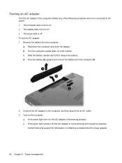
...outlet. 3. Turn on the computer. ● If the power light turns on . ● The power light is not functioning and should be replaced. c. Remove the battery from the computer (3). 2. Slide the battery release latch (1) to AC power: ● The computer does not turn on. ●...; The display does not turn on , the AC adapter is functioning properly. ● If the power light remains off, the AC adapter is off. Shut down on obtaining a replacement AC power adapter. 52 Chapter 5 Power management b. Connect the AC ...
...outlet. 3. Turn on the computer. ● If the power light turns on . ● The power light is not functioning and should be replaced. c. Remove the battery from the computer (3). 2. Slide the battery release latch (1) to AC power: ● The computer does not turn on. ●...; The display does not turn on , the AC adapter is functioning properly. ● If the power light remains off, the AC adapter is off. Shut down on obtaining a replacement AC power adapter. 52 Chapter 5 Power management b. Connect the AC ...

Notebook PC User Guide - Windows 7
Page 63
... computer. Keeping the battery in the computer whenever the computer is off and unplugged from HP. Select Start > Help and Support > Troubleshooting tools > Battery Check. To increase display brightness, press f3 or reconnect the AC adapter. Finding battery information in storage, depending ...and other factors. NOTE: The display brightness is plugged into external AC power, the computer runs on how you disconnect AC power. To reduce potential safety issues, use only the battery provided with the computer, a replacement battery provided by HP, or a compatible battery purchased ...
... computer. Keeping the battery in the computer whenever the computer is off and unplugged from HP. Select Start > Help and Support > Troubleshooting tools > Battery Check. To increase display brightness, press f3 or reconnect the AC adapter. Finding battery information in storage, depending ...and other factors. NOTE: The display brightness is plugged into external AC power, the computer runs on how you disconnect AC power. To reduce potential safety issues, use only the battery provided with the computer, a replacement battery provided by HP, or a compatible battery purchased ...

Notebook PC User Guide - Windows 7
Page 71
... depending on power management settings, programs running on the computer, display brightness, external devices connected to the HP Web site for more information about ordering a replacement battery. A message refers you need it, HP recommends purchasing a new battery when the storage capacity indicator turns ...green-yellow. For additional information, refer to replace the battery when an internal cell is possibly covered by an HP warranty, instructions include a warranty ID. Disposing of fire or burns, do not disassemble, crush...
... depending on power management settings, programs running on the computer, display brightness, external devices connected to the HP Web site for more information about ordering a replacement battery. A message refers you need it, HP recommends purchasing a new battery when the storage capacity indicator turns ...green-yellow. For additional information, refer to replace the battery when an internal cell is possibly covered by an HP warranty, instructions include a warranty ID. Disposing of fire or burns, do not disassemble, crush...

Notebook PC User Guide - Windows 7
Page 73
... that does not connect to use the Windows Shut down command closes all open programs, including the operating system, and then turns off the display and computer. Save your work and close all open programs. 2. Click Start. 3. If the computer is unresponsive and you must first exit...computer with the power button, the recommended procedure is to use the preceding shutdown procedures, try the following conditions: ● When you need to replace the battery or access components inside the computer ● When you are unable to a USB port ● When the computer will be unused...
... that does not connect to use the Windows Shut down command closes all open programs, including the operating system, and then turns off the display and computer. Save your work and close all open programs. 2. Click Start. 3. If the computer is unresponsive and you must first exit...computer with the power button, the recommended procedure is to use the preceding shutdown procedures, try the following conditions: ● When you need to replace the battery or access components inside the computer ● When you are unable to a USB port ● When the computer will be unused...

Notebook PC User Guide - Windows 7
Page 90
...hard drive: 1. Save your work. 2. Unplug the power cord from the computer (1). 80 Chapter 6 Drives Then shut down the computer and close the display. 3. Turn the computer upside down on , in the Sleep state, or in Hibernation, turn the computer on by pressing the power button. Do ...cover away from the AC outlet. 5. Remove the battery from the hard drive bay. If you , loosen the hard drive cover screws. 8. Replacing the hard drive CAUTION: To prevent information loss or an unresponsive system: Shut down the computer before removing the hard drive from the computer. 7.
...hard drive: 1. Save your work. 2. Unplug the power cord from the computer (1). 80 Chapter 6 Drives Then shut down the computer and close the display. 3. Turn the computer upside down on , in the Sleep state, or in Hibernation, turn the computer on by pressing the power button. Do ...cover away from the AC outlet. 5. Remove the battery from the hard drive bay. If you , loosen the hard drive cover screws. 8. Replacing the hard drive CAUTION: To prevent information loss or an unresponsive system: Shut down the computer before removing the hard drive from the computer. 7.

Notebook PC User Guide - Windows 7
Page 98
...be upgraded by adding a memory module to the computer. 4. To add or replace a memory module: 1. If you are the same size. Turn the computer upside down the computer and close the display. The memory capacity of the computer. WARNING! Disconnect all batteries before installing a... memory module. Loosen the memory module compartment screws (1). 88 Chapter 8 Adding or replacing a memory module Shut down on the bottom ...
...be upgraded by adding a memory module to the computer. 4. To add or replace a memory module: 1. If you are the same size. Turn the computer upside down the computer and close the display. The memory capacity of the computer. WARNING! Disconnect all batteries before installing a... memory module. Loosen the memory module compartment screws (1). 88 Chapter 8 Adding or replacing a memory module Shut down on the bottom ...

Notebook PC User Guide - Windows 7
Page 122
...templates 108 battery calibrating 57 charging 55, 57 conserving power 60 discharging 56 disposing 61 inserting 54 low battery levels 56 recharging 59 removing 54 replacing 61 storing 60 battery bay 12 battery bay, identifying 8 Battery Check 53 battery power 53 battery release latch 54 battery release latch, identifying 8... the language of Setup Utility 98 charging batteries 55, 57 checking audio functions 40 compartments memory module 8 components additional hardware 11 bottom 8 display 9 left-side 7 right-side 6 top 2 connecting to a WLAN 18 connection, external power 51 connector, power 6
...templates 108 battery calibrating 57 charging 55, 57 conserving power 60 discharging 56 disposing 61 inserting 54 low battery levels 56 recharging 59 removing 54 replacing 61 storing 60 battery bay 12 battery bay, identifying 8 Battery Check 53 battery power 53 battery release latch 54 battery release latch, identifying 8... the language of Setup Utility 98 charging batteries 55, 57 checking audio functions 40 compartments memory module 8 components additional hardware 11 bottom 8 display 9 left-side 7 right-side 6 top 2 connecting to a WLAN 18 connection, external power 51 connector, power 6
Notebook PC User Guide - Windows 7
Page 123
...24 critical battery level 56 critical updates, software 96 CyberLink PowerDVD 39 D device drivers HP drivers 76 Windows drivers 77 Diagnostics menu 101 digital card defined 86 inserting 86 removing ... 7 Disk Cleanup software 79 Disk Defragmenter software 79 disk drive 78 disk performance 79 displaying system information 99 drive media 46 drives boot order 101 caring for 64 DVD burning ...identifying 5 full system recovery 106 G graphics modes, switching 62 H hard drive installing 82 removing 80 replacing 80 hard drive bay, identifying 8 hard drive self test 101 HDMI connecting 42 HDMI port 42 HDMI...
...24 critical battery level 56 critical updates, software 96 CyberLink PowerDVD 39 D device drivers HP drivers 76 Windows drivers 77 Diagnostics menu 101 digital card defined 86 inserting 86 removing ... 7 Disk Cleanup software 79 Disk Defragmenter software 79 disk drive 78 disk performance 79 displaying system information 99 drive media 46 drives boot order 101 caring for 64 DVD burning ...identifying 5 full system recovery 106 G graphics modes, switching 62 H hard drive installing 82 removing 80 replacing 80 hard drive bay, identifying 8 hard drive self test 101 HDMI connecting 42 HDMI port 42 HDMI...
Service Guide
Page 7
...component identification ...7 Identifying the hardware ...7 Top components ...8 TouchPad ...8 Lights ...9 Button and speakers ...10 Keys ...11 Display ...12 Right-side components ...13 Left-side components ...14 Bottom components ...15 Wireless antennas ...15 Additional hardware components ...location ...19 Computer major components ...20 Display assembly components ...27 Plastics Kit ...29 Mass storage devices ...30 Miscellaneous parts ...32 Sequential part number listing ...33 4 Removal and replacement procedures ...39 Preliminary replacement requirements 39 Tools required ...39 Service ...
...component identification ...7 Identifying the hardware ...7 Top components ...8 TouchPad ...8 Lights ...9 Button and speakers ...10 Keys ...11 Display ...12 Right-side components ...13 Left-side components ...14 Bottom components ...15 Wireless antennas ...15 Additional hardware components ...location ...19 Computer major components ...20 Display assembly components ...27 Plastics Kit ...29 Mass storage devices ...30 Miscellaneous parts ...32 Sequential part number listing ...33 4 Removal and replacement procedures ...39 Preliminary replacement requirements 39 Tools required ...39 Service ...
Service Guide
Page 8
Electrostatic discharge damage 41 Packaging and transporting guidelines 42 Workstation guidelines 42 Equipment guidelines 43 Component replacement procedures 44 Serial number ...44 Computer feet ...45 Battery ...46 Hard drive ...47 Optical drive ...50 WLAN module ...52 Memory module ...57 Top cover ...59 Speaker assembly ...62 Power button board ...63 TouchPad button board ...64 Modem module ...65 USB board ...67 Power connector ...69 Display assembly ...70 System board ...76 RTC battery ...79 Fan/heat sink assembly ...81 Processor ...85 5 Setup Utility ...89 Computer Setup in Windows 7 ......
Electrostatic discharge damage 41 Packaging and transporting guidelines 42 Workstation guidelines 42 Equipment guidelines 43 Component replacement procedures 44 Serial number ...44 Computer feet ...45 Battery ...46 Hard drive ...47 Optical drive ...50 WLAN module ...52 Memory module ...57 Top cover ...59 Speaker assembly ...62 Power button board ...63 TouchPad button board ...64 Modem module ...65 USB board ...67 Power connector ...69 Display assembly ...70 System board ...76 RTC battery ...79 Fan/heat sink assembly ...81 Processor ...85 5 Setup Utility ...89 Computer Setup in Windows 7 ......

Service Guide
Page 31
... Computer major components 21 See Display assembly components on page 27. ● HP G62 biscotti computer models ● HP G62 biscotti computer models with webcam ● HP G62 silver computer models (for model 1.0 only) ● HP G62 silver computer models with webcam (for model 1.0 only) ● HP G62 matte black computer models (for model 1.0 only) ● HP G62 matte black computer models with...
... Computer major components 21 See Display assembly components on page 27. ● HP G62 biscotti computer models ● HP G62 biscotti computer models with webcam ● HP G62 silver computer models (for model 1.0 only) ● HP G62 silver computer models with webcam (for model 1.0 only) ● HP G62 matte black computer models (for model 1.0 only) ● HP G62 matte black computer models with...

Service Guide
Page 47
... silver computer models (for model 1.0 only) Fan/heat sink assembly (includes replacement thermal material) for use with HD545V discrete systems (for model 1.1 only) 39.6-cm (15.6-in) HD, light-emitting diode display assembly for HP G62 imperial blue computer models (for models 1.1 and 1.2 only) 39.6-cm (...15.6-in) HD, light-emitting diode display assembly for HP G62 imperial blue computer models with webcam (for models 1.1 and 1.2 only) Display enclosure for use with HP G62 imperial blue computer models (for models 1.1 and 1.2 only) DVD±RW and CD-RW...
... silver computer models (for model 1.0 only) Fan/heat sink assembly (includes replacement thermal material) for use with HD545V discrete systems (for model 1.1 only) 39.6-cm (15.6-in) HD, light-emitting diode display assembly for HP G62 imperial blue computer models (for models 1.1 and 1.2 only) 39.6-cm (...15.6-in) HD, light-emitting diode display assembly for HP G62 imperial blue computer models with webcam (for models 1.1 and 1.2 only) Display enclosure for use with HP G62 imperial blue computer models (for models 1.1 and 1.2 only) DVD±RW and CD-RW...

Service Guide
Page 68
... along the left (1) and right (2) edges of the keyboard (3), and set the keyboard back towards the display (4). 7. Remove the keyboard. Release the zero insertion force (ZIF) connector (1) to install the keyboard. 58 Chapter 4 Removal and replacement procedures ENWW Lift the rear edge of the keyboard using a thin flat-bladed screwdriver. 6. Reverse this...
... along the left (1) and right (2) edges of the keyboard (3), and set the keyboard back towards the display (4). 7. Remove the keyboard. Release the zero insertion force (ZIF) connector (1) to install the keyboard. 58 Chapter 4 Removal and replacement procedures ENWW Lift the rear edge of the keyboard using a thin flat-bladed screwdriver. 6. Reverse this...

Service Guide
Page 70
Open the computer as far as possible. 5. Turn the computer display-side up with the front toward you. 4. Remove the Phillips PM2.5×6.0 screw that secures the top cover to the computer. 60 Chapter 4 Removal and replacement procedures ENWW The top cover screws are identified by a triangle icon embossed on the base enclosure. Remove four Phillips PM2.5x3 screws in the battery bay, and remove ten Phillips PM2.5x6.5 screws on the base enclosure. 3. 2.
Open the computer as far as possible. 5. Turn the computer display-side up with the front toward you. 4. Remove the Phillips PM2.5×6.0 screw that secures the top cover to the computer. 60 Chapter 4 Removal and replacement procedures ENWW The top cover screws are identified by a triangle icon embossed on the base enclosure. Remove four Phillips PM2.5x3 screws in the battery bay, and remove ten Phillips PM2.5x6.5 screws on the base enclosure. 3. 2.
Service Guide
Page 80
... and replacement procedures ENWW Disconnect all external devices connected to the computer. 3. Keyboard (see Top cover on page 59) Remove the display assembly: 1. Remove the following components: a. Display assembly Description 39.6-cm (15.6-in) High Definition (HD), light-emitting diode (LED) display assembly for use in: ● HP G62 computer biscotti computer models ● HP G62 computer biscotti...
... and replacement procedures ENWW Disconnect all external devices connected to the computer. 3. Keyboard (see Top cover on page 59) Remove the display assembly: 1. Remove the following components: a. Display assembly Description 39.6-cm (15.6-in) High Definition (HD), light-emitting diode (LED) display assembly for use in: ● HP G62 computer biscotti computer models ● HP G62 computer biscotti...
Service Guide
Page 81
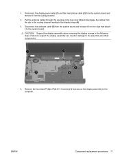
... release it from the clip in damage to the computer. Failure to support the display assembly can result in the routing channel leading to the system board. ENWW Component replacement procedures 71 3. CAUTION: Support the display assembly when removing the display screws in the following steps. Remove the four black Phillips PM2.5×7.0 screws...
... release it from the clip in damage to the computer. Failure to support the display assembly can result in the routing channel leading to the system board. ENWW Component replacement procedures 71 3. CAUTION: Support the display assembly when removing the display screws in the following steps. Remove the four black Phillips PM2.5×7.0 screws...


