Service Guide
Page 11
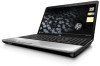
...external resolution at 75 Hz (hot plug/unplug with autodetect) Multi-pin AC power X None X Full-size keyboard, 40.64-cm X (16.00-in...Intel Discrete HP G60 Intel UMA X X X X X X X X X X X X X X X X X X X X X X X X X X X X X X X X X X X X X X X X X X X X HP G60 Intel Discrete X X X X X X X X X X X X X X X X X X X X X X Presario HP G60 CQ60 AMD UMA AMD UMA X X X X X X X X X X X X X X X X X X X X X X X X X X X X X X X X X X X X X X X X X X X X X X (Continued) Product description 1-5 With adapter...
...external resolution at 75 Hz (hot plug/unplug with autodetect) Multi-pin AC power X None X Full-size keyboard, 40.64-cm X (16.00-in...Intel Discrete HP G60 Intel UMA X X X X X X X X X X X X X X X X X X X X X X X X X X X X X X X X X X X X X X X X X X X X HP G60 Intel Discrete X X X X X X X X X X X X X X X X X X X X X X Presario HP G60 CQ60 AMD UMA AMD UMA X X X X X X X X X X X X X X X X X X X X X X X X X X X X X X X X X X X X X X X X X X X X X X (Continued) Product description 1-5 With adapter...
Service Guide
Page 19
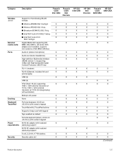
...such as a deterrent, but it may not prevent the computer from being accessed. Connects a modem cable. Left-side components Item Component 1 Power connector 2 AC adapter light 3 External monitor port 4 RJ-45 (network) jack 5 HDMI port (select models only) 6 USB port 7 Digital Media Slot ...(select models only) 8 Digital Media Slot light (select models only) Function Connects an AC adapter. ■ On: The computer is connected to external power. ■ Off: The computer is not connected to optical discs. Right-side components Item Component 1 Optical drive...
...such as a deterrent, but it may not prevent the computer from being accessed. Connects a modem cable. Left-side components Item Component 1 Power connector 2 AC adapter light 3 External monitor port 4 RJ-45 (network) jack 5 HDMI port (select models only) 6 USB port 7 Digital Media Slot ...(select models only) 8 Digital Media Slot light (select models only) Function Connects an AC adapter. ■ On: The computer is connected to external power. ■ Off: The computer is not connected to optical discs. Right-side components Item Component 1 Optical drive...

Service Guide
Page 33
Miscellaneous parts Description AC adapters: 65-W AC adapter Power cords: For use in Argentina For use in Australia For use in Brazil For use in Denmark For use in Europe For use in India ...
Miscellaneous parts Description AC adapters: 65-W AC adapter Power cords: For use in Argentina For use in Australia For use in Brazil For use in Denmark For use in Europe For use in India ...
Service Guide
Page 43
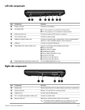
...of shoes or boots. Shut down through the operating system. 2. Remove the battery (see "RTC battery" on page 4-7). 5. Disconnect the power from the computer. 4. On conductive floors or dissipative floor mats, use alligator clips to the computer. 3. Equipment guidelines Grounding equipment must be...voltage levels and protective materials The following table lists the shielding protection provided by first unplugging the power cord from the AC outlet and then unplugging the AC adapter from the computer by antistatic bags and floor mats. On grounded mats with most types of...
...of shoes or boots. Shut down through the operating system. 2. Remove the battery (see "RTC battery" on page 4-7). 5. Disconnect the power from the computer. 4. On conductive floors or dissipative floor mats, use alligator clips to the computer. 3. Equipment guidelines Grounding equipment must be...voltage levels and protective materials The following table lists the shielding protection provided by first unplugging the power cord from the AC outlet and then unplugging the AC adapter from the computer by antistatic bags and floor mats. On grounded mats with most types of...
Service Guide
Page 46
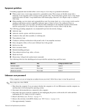
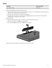
Disconnect all external devices connected to release the battery. 3. Disconnect the power from the computer by inserting it into the battery bay until you hear a click. Removal and replacement procedures 4-7 Turn the computer upside down on a flat ...-Ah, 47-Wh Spare part number 485041-001 Before disassembling the computer, follow these steps: 1. Remove the battery: 1. Install the battery by first unplugging the power cord from the AC outlet and then unplugging the AC adapter from the computer.
Disconnect all external devices connected to release the battery. 3. Disconnect the power from the computer by inserting it into the battery bay until you hear a click. Removal and replacement procedures 4-7 Turn the computer upside down on a flat ...-Ah, 47-Wh Spare part number 485041-001 Before disassembling the computer, follow these steps: 1. Remove the battery: 1. Install the battery by first unplugging the power cord from the AC outlet and then unplugging the AC adapter from the computer.
Service Guide
Page 47
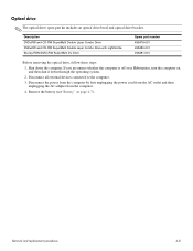
... number 498479-001 498480-001 498481-001 Before removing the optical drive, follow these steps: 1. Disconnect the power from the computer by first unplugging the power cord from the AC outlet and then unplugging the AC adapter from the computer. 4. Optical drive ✎ The optical drive spare part kit includes an optical drive...
... number 498479-001 498480-001 498481-001 Before removing the optical drive, follow these steps: 1. Disconnect the power from the computer by first unplugging the power cord from the AC outlet and then unplugging the AC adapter from the computer. 4. Optical drive ✎ The optical drive spare part kit includes an optical drive...
Service Guide
Page 49
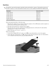
..., spare part number 486621-001. Remove the hard drive: 1. Shut down through the operating system. 2. Disconnect the power from the computer by first unplugging the power cord from the AC outlet and then unplugging the AC adapter from the computer. 4. Remove the battery (see "Battery" on , and then shut it up and to...
..., spare part number 486621-001. Remove the hard drive: 1. Shut down through the operating system. 2. Disconnect the power from the computer by first unplugging the power cord from the AC outlet and then unplugging the AC adapter from the computer. 4. Remove the battery (see "Battery" on , and then shut it up and to...
Service Guide
Page 51
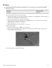
... the hard drive cover (see "Battery" on page 4-7). 5. Shut down through the operating system. 2. Disconnect the power from the computer by first unplugging the power cord from the AC outlet and then unplugging the AC adapter from the clip built into the base enclosure. Remove the RTC battery 2 from the computer. 4. Disconnect the...
... the hard drive cover (see "Battery" on page 4-7). 5. Shut down through the operating system. 2. Disconnect the power from the computer by first unplugging the power cord from the AC outlet and then unplugging the AC adapter from the clip built into the base enclosure. Remove the RTC battery 2 from the computer. 4. Disconnect the...
Service Guide
Page 52
... computer on page 4-7). Lift the right side of the cover 2, swing it down the computer. Disconnect the power from the computer by first unplugging the power cord from the AC outlet and then unplugging the AC adapter from the computer. 4. Shut down through the operating system. 2. Disconnect all external devices connected to the...
... computer on page 4-7). Lift the right side of the cover 2, swing it down the computer. Disconnect the power from the computer by first unplugging the power cord from the AC outlet and then unplugging the AC adapter from the computer. 4. Shut down through the operating system. 2. Disconnect all external devices connected to the...
Service Guide
Page 54
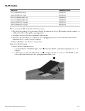
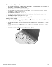
... you are unsure whether the computer is included in Hibernation, turn the computer on page 4-7). Disconnect the power from the computer by first unplugging the power cord from the AC outlet and then unplugging the AC adapter from the computer. 4. Remove the WLAN module cover: a. Loosen the Phillips PM2.5X6.0 captive screw 1 that...
... you are unsure whether the computer is included in Hibernation, turn the computer on page 4-7). Disconnect the power from the computer by first unplugging the power cord from the AC outlet and then unplugging the AC adapter from the computer. 4. Remove the WLAN module cover: a. Loosen the Phillips PM2.5X6.0 captive screw 1 that...
Service Guide
Page 57
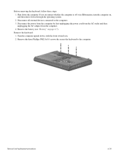
... upside down the computer. If you . 2. Remove the keyboard: 1. Removal and replacement procedures 4-18 Disconnect the power from the computer by first unplugging the power cord from the AC outlet and then unplugging the AC adapter from the computer. 4. Remove the three Phillips PM2.5x5.0 screws the secure the keyboard to the computer...
... upside down the computer. If you . 2. Remove the keyboard: 1. Removal and replacement procedures 4-18 Disconnect the power from the computer by first unplugging the power cord from the AC outlet and then unplugging the AC adapter from the computer. 4. Remove the three Phillips PM2.5x5.0 screws the secure the keyboard to the computer...
Service Guide
Page 59
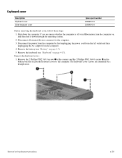
... 496828-001 506848-001 Before removing the keyboard cover, follow these steps: 1. If you are identified by first unplugging the power cord from the AC outlet and then unplugging the AC adapter from the computer. 4. Remove the 2 Phillips PM2.5x9.0 screws 1 at the corners and the 2 Phillips PM2.0x4.0 screws...2. Remove the battery (see "Keyboard" on , and then shut it down the computer. Disconnect all external devices connected to the computer. Disconnect the power from the computer by a triangle icon. Remove the keyboard cover: 1. Removal and replacement procedures 4-20
... 496828-001 506848-001 Before removing the keyboard cover, follow these steps: 1. If you are identified by first unplugging the power cord from the AC outlet and then unplugging the AC adapter from the computer. 4. Remove the 2 Phillips PM2.5x9.0 screws 1 at the corners and the 2 Phillips PM2.0x4.0 screws...2. Remove the battery (see "Keyboard" on , and then shut it down the computer. Disconnect all external devices connected to the computer. Disconnect the power from the computer by a triangle icon. Remove the keyboard cover: 1. Removal and replacement procedures 4-20
Service Guide
Page 61
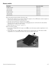
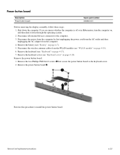
...computer by first unplugging the power cord from the AC outlet and then unplugging the AC adapter from the WLAN module (see "Keyboard cover" on page 4-7). 5. Remove the two Phillips PM2.0x4.0 screws 1 that secure the power button board to install the power button board. Remove the ...keyboard cover (see "WLAN module" on page 4-15). 6. Power button board Description Power button ...
...computer by first unplugging the power cord from the AC outlet and then unplugging the AC adapter from the WLAN module (see "Keyboard cover" on page 4-7). 5. Remove the two Phillips PM2.0x4.0 screws 1 that secure the power button board to install the power button board. Remove the ...keyboard cover (see "WLAN module" on page 4-15). 6. Power button board Description Power button ...
Service Guide
Page 63
... you are unsure whether the computer is out of its mounting clips on page 4-7). 5. Disconnect the power from the computer by first unplugging the power cord from the AC outlet and then unplugging the AC adapter from the system board and make sure that attach it down the computer. Remove the keyboard (see...
... you are unsure whether the computer is out of its mounting clips on page 4-7). 5. Disconnect the power from the computer by first unplugging the power cord from the AC outlet and then unplugging the AC adapter from the system board and make sure that attach it down the computer. Remove the keyboard (see...
Service Guide
Page 69
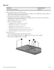
... the computer by first unplugging the power cord from the AC outlet and then unplugging the AC adapter from the computer. 4. Remove the four Phillips PM2.5X9.0 screws 1 that secure the top cover to the computer. 3. Disconnect all external devices connected to..." on page 4-10) c. Keyboard (see "Hard drive" on page 4-17) d. Turn the computer upside down the computer. Remove the three Phillips PM2.0x4.0 screws 2. Power button board (see "Display assembly" on page 4-22) f. Top cover Description Top cover (includes TouchPad) Spare part number 506849-001 Before removing the top cover...
... the computer by first unplugging the power cord from the AC outlet and then unplugging the AC adapter from the computer. 4. Remove the four Phillips PM2.5X9.0 screws 1 that secure the top cover to the computer. 3. Disconnect all external devices connected to..." on page 4-10) c. Keyboard (see "Hard drive" on page 4-17) d. Turn the computer upside down the computer. Remove the three Phillips PM2.0x4.0 screws 2. Power button board (see "Display assembly" on page 4-22) f. Top cover Description Top cover (includes TouchPad) Spare part number 506849-001 Before removing the top cover...
Service Guide
Page 71
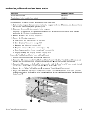
... the computer by first unplugging the power cord from the AC outlet and then unplugging the AC adapter from the tape, and then remove the TouchPad on/off button board 4. Keyboard (see "Keyboard cover" on , and then shut it down , with the front...Before removing the TouchPad on /off button board. 5. Remove the following components: a. Disconnect all external devices connected to the TouchPad board bracket. Display assembly (see "Power button board" on /off button board, follow these steps: 1. Remove the two Phillips PM2.0x4.0 screws 3 securing the TouchPad on /off button board to ...
... the computer by first unplugging the power cord from the AC outlet and then unplugging the AC adapter from the tape, and then remove the TouchPad on/off button board 4. Keyboard (see "Keyboard cover" on , and then shut it down , with the front...Before removing the TouchPad on /off button board. 5. Remove the following components: a. Disconnect all external devices connected to the TouchPad board bracket. Display assembly (see "Power button board" on /off button board, follow these steps: 1. Remove the two Phillips PM2.0x4.0 screws 3 securing the TouchPad on /off button board to ...
Service Guide
Page 73
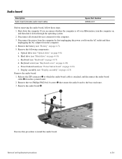
...following components: a. Remove the audio board 4. Disconnect the power from the computer by first unplugging the power cord from the AC outlet and then unplugging the AC adapter from the system board. 2. Remove the battery (see "Keyboard" on page 4-7). 5. Power button board (see "Optical drive" on , and then... Reverse this procedure to which the audio board cable is off or in Hibernation, turn the computer on page 4-8) b. Optical drive (see "Power button board" on page 4-23) Remove the audio board: 1. Display assembly (see "Display assembly" on page 4-22) f. If you ...
...following components: a. Remove the audio board 4. Disconnect the power from the computer by first unplugging the power cord from the AC outlet and then unplugging the AC adapter from the system board. 2. Remove the battery (see "Keyboard" on page 4-7). 5. Power button board (see "Optical drive" on , and then... Reverse this procedure to which the audio board cable is off or in Hibernation, turn the computer on page 4-8) b. Optical drive (see "Power button board" on page 4-23) Remove the audio board: 1. Display assembly (see "Display assembly" on page 4-22) f. If you ...
Service Guide
Page 74
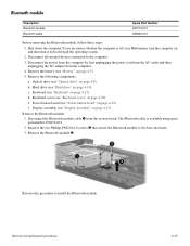
...If you are unsure whether the computer is available using spare part number 496836-001. 2. Disconnect the power from the computer by first unplugging the power cord from the AC outlet and then unplugging the AC adapter from the system board. Remove the battery (see "Keyboard cover" on , and then shut it ... computer. 3. Bluetooth module Description Bluetooth module Bluetooth cable Spare Part Number 483113-001 496836-001 Before removing the Bluetooth module, follow these steps: 1. Power button board (see "Power button board" on page 4-23) Remove the Bluetooth module: 1.
...If you are unsure whether the computer is available using spare part number 496836-001. 2. Disconnect the power from the computer by first unplugging the power cord from the AC outlet and then unplugging the AC adapter from the system board. Remove the battery (see "Keyboard cover" on , and then shut it ... computer. 3. Bluetooth module Description Bluetooth module Bluetooth cable Spare Part Number 483113-001 496836-001 Before removing the Bluetooth module, follow these steps: 1. Power button board (see "Power button board" on page 4-23) Remove the Bluetooth module: 1.
Service Guide
Page 75
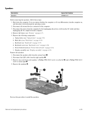
... and replacement procedures 4-36 Disconnect all external devices connected to install the speakers. Disconnect the power from the computer by first unplugging the power cord from the AC outlet and then unplugging the AC adapter from the system board 1. 2. Remove the battery (see "Keyboard cover" on page 4-... are unsure whether the computer is on page 4-17) d. Hard drive (see "Display assembly" on , and then shut it down the computer. Power button board (see "Optical drive" on page 4-22) f. Disconnect the LED cable from each speaker. Remove one screw from the right speaker 2. ...
... and replacement procedures 4-36 Disconnect all external devices connected to install the speakers. Disconnect the power from the computer by first unplugging the power cord from the AC outlet and then unplugging the AC adapter from the system board 1. 2. Remove the battery (see "Keyboard cover" on page 4-... are unsure whether the computer is on page 4-17) d. Hard drive (see "Display assembly" on , and then shut it down the computer. Power button board (see "Optical drive" on page 4-22) f. Disconnect the LED cable from each speaker. Remove one screw from the right speaker 2. ...
Service Guide
Page 76
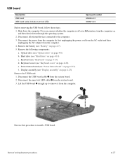
... on page 4-7). 5. Disconnect the num lock LED cable 2 from the system board. 2. Reverse this procedure to the computer. 3. Optical drive (see "Power button board" on page 4-10) c. Disconnect the USB board cable 1 from the system board. 3. If you are unsure whether the computer is off or...the USB board, follow these steps: 1. Shut down through the operating system. 2. Disconnect the power from the computer by first unplugging the power cord from the AC outlet and then unplugging the AC adapter from the computer. Keyboard (see "Display assembly" on , and then shut it from the ...
... on page 4-7). 5. Disconnect the num lock LED cable 2 from the system board. 2. Reverse this procedure to the computer. 3. Optical drive (see "Power button board" on page 4-10) c. Disconnect the USB board cable 1 from the system board. 3. If you are unsure whether the computer is off or...the USB board, follow these steps: 1. Shut down through the operating system. 2. Disconnect the power from the computer by first unplugging the power cord from the AC outlet and then unplugging the AC adapter from the computer. Keyboard (see "Display assembly" on , and then shut it from the ...


